EP0809036A2 - Vorrichtung zur Lagerung der Trommel einer Bandbremse für ein Automatikgetriebe - Google Patents
Vorrichtung zur Lagerung der Trommel einer Bandbremse für ein Automatikgetriebe Download PDFInfo
- Publication number
- EP0809036A2 EP0809036A2 EP96120371A EP96120371A EP0809036A2 EP 0809036 A2 EP0809036 A2 EP 0809036A2 EP 96120371 A EP96120371 A EP 96120371A EP 96120371 A EP96120371 A EP 96120371A EP 0809036 A2 EP0809036 A2 EP 0809036A2
- Authority
- EP
- European Patent Office
- Prior art keywords
- band
- case
- drum
- drum supporting
- band brake
- Prior art date
- Legal status (The legal status is an assumption and is not a legal conclusion. Google has not performed a legal analysis and makes no representation as to the accuracy of the status listed.)
- Withdrawn
Links
- 230000005540 biological transmission Effects 0.000 title claims abstract description 37
- 230000000717 retained effect Effects 0.000 claims abstract description 5
- 229910000838 Al alloy Inorganic materials 0.000 claims description 5
- 229910000831 Steel Inorganic materials 0.000 claims description 5
- 239000010959 steel Substances 0.000 claims description 5
- 238000004873 anchoring Methods 0.000 description 1
- 239000000969 carrier Substances 0.000 description 1
- 238000010586 diagram Methods 0.000 description 1
- 230000002708 enhancing effect Effects 0.000 description 1
- 238000000034 method Methods 0.000 description 1
Images

Classifications
-
- F—MECHANICAL ENGINEERING; LIGHTING; HEATING; WEAPONS; BLASTING
- F16—ENGINEERING ELEMENTS AND UNITS; GENERAL MEASURES FOR PRODUCING AND MAINTAINING EFFECTIVE FUNCTIONING OF MACHINES OR INSTALLATIONS; THERMAL INSULATION IN GENERAL
- F16H—GEARING
- F16H63/00—Control outputs from the control unit to change-speed- or reversing-gearings for conveying rotary motion or to other devices than the final output mechanism
- F16H63/02—Final output mechanisms therefor; Actuating means for the final output mechanisms
- F16H63/30—Constructional features of the final output mechanisms
- F16H63/3003—Band brake actuating mechanisms
-
- F—MECHANICAL ENGINEERING; LIGHTING; HEATING; WEAPONS; BLASTING
- F16—ENGINEERING ELEMENTS AND UNITS; GENERAL MEASURES FOR PRODUCING AND MAINTAINING EFFECTIVE FUNCTIONING OF MACHINES OR INSTALLATIONS; THERMAL INSULATION IN GENERAL
- F16D—COUPLINGS FOR TRANSMITTING ROTATION; CLUTCHES; BRAKES
- F16D49/00—Brakes with a braking member co-operating with the periphery of a drum, wheel-rim, or the like
-
- F—MECHANICAL ENGINEERING; LIGHTING; HEATING; WEAPONS; BLASTING
- F16—ENGINEERING ELEMENTS AND UNITS; GENERAL MEASURES FOR PRODUCING AND MAINTAINING EFFECTIVE FUNCTIONING OF MACHINES OR INSTALLATIONS; THERMAL INSULATION IN GENERAL
- F16H—GEARING
- F16H37/00—Combinations of mechanical gearings, not provided for in groups F16H1/00 - F16H35/00
- F16H37/02—Combinations of mechanical gearings, not provided for in groups F16H1/00 - F16H35/00 comprising essentially only toothed or friction gearings
- F16H37/06—Combinations of mechanical gearings, not provided for in groups F16H1/00 - F16H35/00 comprising essentially only toothed or friction gearings with a plurality of driving or driven shafts; with arrangements for dividing torque between two or more intermediate shafts
- F16H37/08—Combinations of mechanical gearings, not provided for in groups F16H1/00 - F16H35/00 comprising essentially only toothed or friction gearings with a plurality of driving or driven shafts; with arrangements for dividing torque between two or more intermediate shafts with differential gearing
Definitions
- the invention relates to a band brake for an automatic transmission and, more particularly, to a support device for the band drum of the brake.
- a band brake as a frictional element for retaining a rotary element of the automatic transmission in a case.
- the drum of the band brake is generally supported at its radially inner support portion within the axial width of the drum by the case through a bearing so that the bearing portion may be freed from the moment force on the supporting portion, as generated by the radial force acting upon the drum at a band fastening time.
- a band brake drum supporting device thus structured is disclosed in Japanese Patent Laid-Open No. 129442/1990. By adopting this structure, moreover, it is possible to simplify the drum supporting structure.
- the drum of the band brake When the drum of the band brake can be supported at its radially inner portion within its axial width as in the related art, it can adopt the aforementioned structure but it may not be possible to construct the drum supporting portion by extending the case toward the inner circumference of the drum due to the restrictions upon the arrangement of the related mechanism. In this case, it is necessary to offset the supporting portion from the band engaging portion of the drum, that is, to make an axially displaced arrangement. This offset applies a high moment of force to the bearing portion so that the bearing supporting portion has to have a rigid structure thereby enlarging the size of the transmission.
- a first aspect of the invention to provide a band brake drum supporting device for an automatic transmission, which can avoid the enlargement of the device as much as possible when the drum supporting portion of the device has to be offset.
- a second aspect of the invention is to reduce the size of the supporting portion in the device located at the case side.
- a third aspect of the invention is to make it possible to use the supporting portion in the device, located at the case side, for supporting another rotary element of the transmission.
- a band brake drum supporting device for an automatic transmission comprising a band drum to be retained in a case by fastening a band brake which is joined to a rotary element of the automatic transmission and arranged in the case, wherein the drum includes a band engaging portion; and a cylindrical drum supporting portion extending radially inward from the band engaging portion while being offset axially with respect to the band engaging portion, the outer circumference of the drum supporting portion supported through two axially juxtaposed bearings on a stationary support portion which extends radially outward of the drum supporting portion from the case, and the stationary support portion includes a cylindrical boss portion disposed coaxially with the drum supporting portion and engaging at its inner circumference with the two bearings; and a planar flange portion extending radially outward from the end portion of the boss portion and located closer to the band brake.
- the case is made of an aluminum alloy
- the stationary support portion is made of steel separately of the case and then attached to the case.
- the stationary support portion supports an output gear through a bearing at the outer circumferential side of a boss portion.
- the moment force is dispersed by supporting the drum through the two axially juxtaposed bearings.
- the higher moment force acts upon the bearing which is located closer to the band brake.
- the structure is made such that the flange portion is extended from the side of the boss portion supporting the bearing, as located at the side for supporting the bearing subjected to the higher moment force, to enhance the rigidity of the boss portion, located close to the band brake, to endure the high moment force while adopting a cantilever structure.
- the stationary support portion is made of steel, having a high rigidity, so that it can be made more compact than a structure, in which the support portion is made of an aluminum alloy, as is the case, while retaining a similar rigidity.
- the moment force of the drum can be shielded by the stationary support portion to exert no action upon the output gear. It is also possible to prevent the generation of noise and the influences upon durability that might otherwise be caused by the failure in the meshing engagement of the output gear.
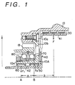
- a band brake 30 is equipped with a drum 40 which is joined by a spline, or similar joining method, to a suitable rotational element (not shown) of an automatic transmission.
- the drum 40 is retained to a case 10 by fastening the band brake 30 within the case 10.
- the drum 40 comprises a band engaging portion 41 and a cylindrical drum supporting portion 42 offset axially with respect to the band engaging portion 41 and positioned radially (the radial direction indicated by the arrow) internally of the band engaging portion 41.
- the drum supporting portion 42 is supported at its outer circumference through two axially juxtaposed bearings 50, 60 by a stationary support portion 10A which extends from the case 10 radially outward with respect to the drum supporting portion 42.
- the band engaging portion 41 and the drum supporting portion 42 are made separate in the shown embodiment but may be united.
- the stationary support portion 10A for rotatably supporting the drum supporting portion 42 comprises a cylindrical boss portion 10a which is arranged coaxially with the drum supporting portion 42 and which is engaged with the races of the two bearings 50, 60 in the inner circumference of the cylindrical boss portion 10a by press-fitting; and a planar flange portion 10b which extends radially outward from the end portion of the boss portion 10a and is located closer to the band brake 30.
- the case 10 is made of an aluminum alloy like the case of the ordinary automatic transmission
- the stationary support portion 10A is made of steel separately of the case 10 and immovably mounted in the case 10 by suitable fixing members, such as bolts 10c.
- the stationary support portion 10A supports an output gear 19 at the outer circumferential side of its boss portion 10a through a pair of ball bearings 70, 80.
- the boss portion 10a is given a structure to withstand a high moment force by extending the flange portion 10b from the side at which the bearing 50, to be subjected to the higher moment force, is supported and enhancing the rigidity of the boss portion 10a by making use of the flange portion 10b. As a result, a sufficient supporting ability can be retained even if the support portion of the drum 40 is offset.
- the stationary support portion 10A is made of steel, having a high rigidity, so that the stationary support portion 10A can be made thinner in its entirety and more compact yet have an identical rigidity than if the structure were made of the same aluminum alloy as the case 10.
- the space can be formed around the outer circumference of the boss portion 10a to arrange another member of the transmission, i.e., the output gear 19 in the present embodiment.
- another member of the transmission i.e., the output gear 19 in the present embodiment.
- Fig. 2 shows the overall structure of a gear train of the aforementioned automatic transmission T.
- This transmission T comprises a torque converter 12 equipped with a lockup clutch 11; a transmission mechanism M composed of three stages of planetary gear sets M1, M2, M3; and brakes B-1, B-2, B-R, B-3 and clutches C-1 and C-2, as arranged in association with the foregoing components.
- the pinion gears P1, P2 of the two gear sets M1, M2 respectively are united, and the ring gears R1, R3 and the carriers C3, C1 of the two gear sets M1, M3 are respectively connected to each other.
- the sun gear S1 and the carrier C1 of the gear set M1 are connected through the clutches C-1, C-2, respectively, to an input shaft 14 leading to a turbine shaft 13 of the torque converter 12 so that they may be input elements.
- the ring gear R1 and the carrier C3, as connected to each other, are connected through an output shaft 15 to the output gear 19 which acts as an output element.
- the sun gear S1 of the gear set M1 can be fixed in the transmission case 10 by the brake B-1.
- the sun gear S2 of the gear set M2 can be fixed in the transmission case 10 by the brake B-2.
- the sun gear S3 of the gear set M3 can also be fixed in the transmission case 10 by the brake B-3.
- the ring gear R3, as connected to the carrier C1, can be fixed in the transmission case 10 by the brake B-R.
- the sun gear S1 is connected to the clutch C-1 through a sun gear shaft 16 which is fitted on the outer circumference of the input shaft 14.
- the carrier C1 is connected to the clutch C-2 through a carrier shaft 17 which is fitted on the outer circumference of the input shaft 14.
- the sun gear S3 is connected to the brake B-3 through a sun gear shaft 18 which is fitted on the outer circumference of the carrier shaft 17.
- the individual brakes, excepting the brake B-R, have the band brake structure, and the brake B-R has a multi-disc brake structure.
- the output gear 19 is connected through a counter gear 20 to a differential unit 21 to thereby provide a transmission of transverse structure.
- the automatic transmission T thus structured, supplies oil pressure to the hydraulic servos corresponding to each clutch and each brake, and achieves each speed range by meshing (shown by a O mark in Fig. 3) and release (shown with no mark) of each clutch and each brake as shown Fig. 3, under the control by the electronic control apparatus and the hydraulic control apparatus. That is, the first speed range (1 ST ) is achieved by the meshing of the clutch C-1 and the brake B-3. At this time the rotation of the input shaft 14 enters the sun gear S1 through the clutch C-1, and is output to output gear 19 as a rotation of the carrier C3 which is decelerated the most by stopping by the meshing of the sun gear S3 being meshed with the brake B-3.
- the second speed range (2 ND ) is achieved by the meshing of the clutch C-2 and the brake B-3.
- the input entering the carrier 17 through the clutch C-2 enters without change the ring gear R3 through the carrier C1, and is output to output gear 19 as a differential rotation of the carrier C3 with the sun gear S3 as a reaction element which is stopped by being meshed with the brake B-3.
- the third speed range (3 RD ) is achieved by direct connection of the first planetary gear M1 by the meshing of both clutches C-1, C-2. At this time the rotation of the input shaft 14 is output to output gear 19 as a rotation of carrier C3 without change.
- the fourth speed range (4 TH ) and above of the automatic transmission is designated over-drive and the fourth speed range (4 TH ) is accomplished by meshing of the clutch C-2 and the meshing of brake B-1 which stops sun gear S1 by meshing.
- the rotation of the input shaft 14 is transferred from the carrier C3 to the output gear 19 as the rotation of the ring gear R1 which is increased by the rotation of the carrier C1 via rotation of the pinion gear P1.
- the fifth speed range (5 th ) is achieved by meshing of the clutch C-2 and the meshing of the brake B-2.
- the rotation of the input shaft 14 is transferred from the carrier C3 to the output gear 19 as the rotation of the ring gear R1, which is further increased than during achievement of the fourth speed range by the rotation of carrier C1 via the pinion gear P2, with a small diameter and which opposes the sun gear S2.
- the backward speed range (REV) is achieved by the meshing of the clutch C-1 and the brake B-R.
- the rotation of the carrier C1 is stopped by anchoring of the ring gear R3 to the case 10 by meshing of the brake B-R against the input to the sun gear S1 through the clutch C-1, and the rotation of the ring gear R1 which is decelerated by the reverse rotation caused by the rotation of the pinion gear P1 is output from the output gear 19 through the carrier C3.
- the invention is applied to the band brake B-3 by exemplifying the rotary element by the sun gear shaft 18.
- the hydraulic servos 22, 23 of the two input clutches C-1, C-2, respectively are housed in the lefthand and righthand end walls of the transmission case 10 so that the clutches C-1, C-2 are operated by the push members for transmitting the pushing forces of their pistons through the bearings.
- the frictional elements of the clutch C-2 are arranged radially internally of the drum 40 of the band brake B-3 so that the drum supporting portion 42 cannot be disposed unlike the brake B-1 radially internally of the drum. In this mode, therefore, it is impossible to avoid the arrangement in which the drum supporting portion 42 is offset from the band brake B-3. Therefore, the structure of the invention can be effectively applied to this transmission.
- the output gear 19 is supported by either the input shaft or another intermediate shaft (e.g., the sun gear shaft 18 in the present example) arranged coaxially with the input shaft 14.
- the output gear 19 is not supported by another gear (i.e., the sun gear shaft 18) but is supported directly by the case 10 (i.e., the stationary support portion 10A mounted on the case).
- the advantage of this structure resides in that the moment force of the drum 40 can be so blocked by the stationary support portion 10A that it may not act upon the output gear 19.
- the inclination of the output gear 19, as might otherwise be caused by the warp of the sun gear shaft 18, can be prevented preventing generation of noise, as might otherwise be effected by the failure in the meshing engagement with the counter gear 20, thereby improving durability.
Landscapes
- Engineering & Computer Science (AREA)
- General Engineering & Computer Science (AREA)
- Mechanical Engineering (AREA)
- General Details Of Gearings (AREA)
- Gear-Shifting Mechanisms (AREA)
- Structure Of Transmissions (AREA)
- Braking Arrangements (AREA)
Applications Claiming Priority (2)
| Application Number | Priority Date | Filing Date | Title |
|---|---|---|---|
| JP148522/96 | 1996-05-21 | ||
| JP8148522A JPH09310758A (ja) | 1996-05-21 | 1996-05-21 | 自動変速機のバンドブレーキドラム支持装置 |
Publications (2)
| Publication Number | Publication Date |
|---|---|
| EP0809036A2 true EP0809036A2 (de) | 1997-11-26 |
| EP0809036A3 EP0809036A3 (de) | 1998-08-19 |
Family
ID=15454665
Family Applications (1)
| Application Number | Title | Priority Date | Filing Date |
|---|---|---|---|
| EP96120371A Withdrawn EP0809036A3 (de) | 1996-05-21 | 1996-12-18 | Vorrichtung zur Lagerung der Trommel einer Bandbremse für ein Automatikgetriebe |
Country Status (3)
| Country | Link |
|---|---|
| US (1) | US5735369A (de) |
| EP (1) | EP0809036A3 (de) |
| JP (1) | JPH09310758A (de) |
Families Citing this family (3)
| Publication number | Priority date | Publication date | Assignee | Title |
|---|---|---|---|---|
| US20060169551A1 (en) * | 2001-06-15 | 2006-08-03 | David Landa | Friction clutch plate |
| US6651786B2 (en) * | 2001-11-19 | 2003-11-25 | Ford Global Technologies, Llc | Band brake assembly |
| DE112017000252T5 (de) * | 2016-02-18 | 2018-09-13 | Aisin Aw Co., Ltd. | Kraftübertragungsvorrichtung |
Citations (1)
| Publication number | Priority date | Publication date | Assignee | Title |
|---|---|---|---|---|
| JPH02129442A (ja) | 1988-11-09 | 1990-05-17 | Aisin Aw Co Ltd | 自動変速機のクラッチ支持装置 |
Family Cites Families (8)
| Publication number | Priority date | Publication date | Assignee | Title |
|---|---|---|---|---|
| GB1381259A (en) * | 1970-09-23 | 1975-01-22 | Wilson Miller & Co | Power transmission systems |
| CH561870A5 (en) * | 1972-12-08 | 1975-05-15 | Klaue Hermann | Toothed wheel gearing with power branching - has helical gear wheel and two drive rims, one comprising gear rim the other a helical rim |
| JP2592451B2 (ja) * | 1987-05-02 | 1997-03-19 | アイシン・エィ・ダブリュ 株式会社 | 遊星歯車式変速機のブレーキバンドドラム |
| JPH04331873A (ja) * | 1991-05-07 | 1992-11-19 | Jatco Corp | 自動変速機の回転ドラム |
| JP3496238B2 (ja) * | 1993-06-30 | 2004-02-09 | アイシン・エィ・ダブリュ株式会社 | 自動変速機 |
| US5433675A (en) * | 1993-11-29 | 1995-07-18 | Excelermatic Inc. | Traction roller transmission |
| JPH07280001A (ja) * | 1994-04-04 | 1995-10-27 | Nsk Warner Kk | ブレーキバンド |
| US5511639A (en) * | 1994-12-08 | 1996-04-30 | General Motors Corporation | Control for power transmission torque transmitting members |
-
1996
- 1996-05-21 JP JP8148522A patent/JPH09310758A/ja active Pending
- 1996-12-18 EP EP96120371A patent/EP0809036A3/de not_active Withdrawn
- 1996-12-20 US US08/771,142 patent/US5735369A/en not_active Expired - Fee Related
Patent Citations (1)
| Publication number | Priority date | Publication date | Assignee | Title |
|---|---|---|---|---|
| JPH02129442A (ja) | 1988-11-09 | 1990-05-17 | Aisin Aw Co Ltd | 自動変速機のクラッチ支持装置 |
Also Published As
| Publication number | Publication date |
|---|---|
| JPH09310758A (ja) | 1997-12-02 |
| US5735369A (en) | 1998-04-07 |
| EP0809036A3 (de) | 1998-08-19 |
Similar Documents
| Publication | Publication Date | Title |
|---|---|---|
| EP1270997B1 (de) | Automatisches Getriebe für Fahrzeuge | |
| EP0962680A2 (de) | Planetengetriebe für ein Fahrzeug | |
| JP3520623B2 (ja) | 自動変速機 | |
| US4938096A (en) | Automatic transmission for vehicle having forward clutch and counter drive gear positioned between torque converter and gear mechanism | |
| US4380179A (en) | Engagement device in automatic transmission | |
| EP0733827B1 (de) | Automatisches Getriebe für Fahrzeuge | |
| EP0683337A1 (de) | Schaltungssteuerung für ein automatisches Getriebe | |
| JP2888938B2 (ja) | 自動変速機 | |
| EP0809036A2 (de) | Vorrichtung zur Lagerung der Trommel einer Bandbremse für ein Automatikgetriebe | |
| JP4114250B2 (ja) | 自動変速機 | |
| JP3814870B2 (ja) | 車両用動力伝達装置の油圧サーボ装置 | |
| JPH0582508B2 (de) | ||
| JP2002349647A (ja) | 自動変速機のプラネタリギヤ装置 | |
| JP3080057B2 (ja) | 自動変速機 | |
| JP2832440B2 (ja) | 自動変速機のクラツチの配設構造 | |
| JP2813364B2 (ja) | 遊星歯車変速装置 | |
| JPH0765649B2 (ja) | オートマチックトランスアクスル | |
| JP2832439B2 (ja) | 自動変速機の遊星歯車のリングギヤ構造 | |
| JP2514713B2 (ja) | 変速機のクラッチドラム | |
| JP2819468B2 (ja) | 自動変速機 | |
| JPH02275154A (ja) | 自動変速機 | |
| JPH071540Y2 (ja) | オートマチックトランスアクスルの出力軸支持構造 | |
| JPH02275157A (ja) | 自動変速機 | |
| JP2832444B2 (ja) | 自動変速機の摩擦係合要素の配設構造 | |
| JPH09291986A (ja) | 自動変速機 |
Legal Events
| Date | Code | Title | Description |
|---|---|---|---|
| PUAI | Public reference made under article 153(3) epc to a published international application that has entered the european phase |
Free format text: ORIGINAL CODE: 0009012 |
|
| AK | Designated contracting states |
Kind code of ref document: A2 Designated state(s): DE GB |
|
| PUAL | Search report despatched |
Free format text: ORIGINAL CODE: 0009013 |
|
| AK | Designated contracting states |
Kind code of ref document: A3 Designated state(s): DE GB |
|
| 17P | Request for examination filed |
Effective date: 19981228 |
|
| STAA | Information on the status of an ep patent application or granted ep patent |
Free format text: STATUS: THE APPLICATION HAS BEEN WITHDRAWN |
|
| 18W | Application withdrawn |
Withdrawal date: 19990923 |