EP0808948A2 - Wire rope net for protection against falling rocks, felling or avalanches and method for making same - Google Patents
Wire rope net for protection against falling rocks, felling or avalanches and method for making same Download PDFInfo
- Publication number
- EP0808948A2 EP0808948A2 EP97107691A EP97107691A EP0808948A2 EP 0808948 A2 EP0808948 A2 EP 0808948A2 EP 97107691 A EP97107691 A EP 97107691A EP 97107691 A EP97107691 A EP 97107691A EP 0808948 A2 EP0808948 A2 EP 0808948A2
- Authority
- EP
- European Patent Office
- Prior art keywords
- wire rope
- mesh
- heads
- wire
- rope net
- Prior art date
- Legal status (The legal status is an assumption and is not a legal conclusion. Google has not performed a legal analysis and makes no representation as to the accuracy of the status listed.)
- Granted
Links
Images

Classifications
-
- E—FIXED CONSTRUCTIONS
- E01—CONSTRUCTION OF ROADS, RAILWAYS, OR BRIDGES
- E01F—ADDITIONAL WORK, SUCH AS EQUIPPING ROADS OR THE CONSTRUCTION OF PLATFORMS, HELICOPTER LANDING STAGES, SIGNS, SNOW FENCES, OR THE LIKE
- E01F7/00—Devices affording protection against snow, sand drifts, side-wind effects, snowslides, avalanches or falling rocks; Anti-dazzle arrangements ; Sight-screens for roads, e.g. to mask accident site
- E01F7/04—Devices affording protection against snowslides, avalanches or falling rocks, e.g. avalanche preventing structures, galleries
- E01F7/045—Devices specially adapted for protecting against falling rocks, e.g. galleries, nets, rock traps
Definitions
- the invention relates to a wire rope network for rockfall, logging or avalanche barriers and a method for producing the same.
- wire rope nets also called safety nets
- safety nets are usually arranged between upright beams anchored in the ground and connected to the beams via wire cables.
- These wire ropes can be equipped with spring links or can be guided through rope brakes in order to absorb part of the energy of the material hitting the net.
- wire rope nets are known which are made up of rings.
- the known wire rope nets have a considerable weight and involve a considerable amount of production.
- the invention seeks to remedy this.
- the invention as characterized in the claims, solves the problem of creating a wire rope network for rockfall, logging and avalanche barriers and a method for producing the same, which allows a saving in the amount of the necessary wire ropes and can be produced with little effort is.
- Figure 1 shows a section of a wire rope net, which is composed of several wire ropes 1, 2, 3, ... connected together in the form of meshes. At their ends, the wire ropes 1, 2, 3, ... are connected to one another by conventional connecting parts, loops, clamps, etc., which are indicated by the reference numbers 4 and 5.
- the wire ropes known per se for connecting the wire mesh with supports can, as can be clearly seen in FIG. 1, through the loops 6, 7, 8, 9 of the uppermost wire rope 1, through the loops of the lowest (not visible) wire rope of the complete mesh , and through the outermost loops 6, 10, 11 on the left and right (not visible).
- the wire ropes 1, 2, 3 can be corrugated differently, ie the individual meshes can have different shapes.
- the preferred form is shown in Figure 3. It can be seen that the shape of the mesh is derived from a circular shape.
- the wire rope 1 is drawn in solid lines and the supplementary, geometric circular arc part is indicated by dotted lines and is designated by the reference number 12.
- the head 13 of each stitch 14 describes an arc with a centering angle of more than 180 °.
- the stitches basically have only one stitch head, but no stitch legs. Neighbors Stitches 14 thus directly adjoin one another with their heads 13, the heads 13 each pointing in opposite directions.
- a first wire rope 2 is shaped by means of a shaping device to form the waveform shown in FIG. 2 in such a way that the drawn heads 10, 16, 17, 18,... Are formed. Then a second wire rope 1 is formed in the same way so that the heads 6, 7, 8, 9, ... are formed. Then the wire rope 1 is pushed against the wire rope 2 and all heads 6, 7, 8, 9, ... are inserted through the heads 10, 16, 17, 18, ... from above relative to the plane of the drawing in Figure 2, see above that the arrangement of the two wire cables 1, 2 drawn in Figure 1 is achieved. A subsequent wire rope is then inserted with the heads through the heads 6, 7, 8, 9, ..., and these processes are repeated with further wire ropes until the complete wire rope network is formed.
Landscapes
- Engineering & Computer Science (AREA)
- Architecture (AREA)
- Civil Engineering (AREA)
- Structural Engineering (AREA)
- Devices Affording Protection Of Roads Or Walls For Sound Insulation (AREA)
- Knitting Of Fabric (AREA)
Abstract
Das Drahtseilnetz besteht aus einer Anzahl wellenförmig verlaufender Drahtseile (1; 2; 3), die ein gewirk- oder gestrickförmiges Maschennetz bilden.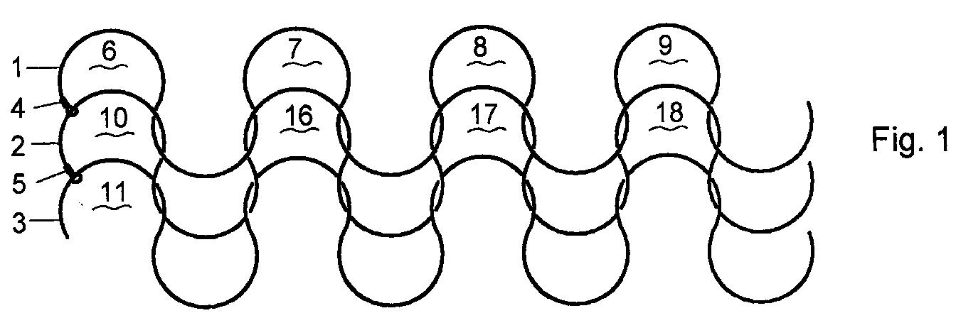
Description
Die Erfindung betrifft ein Drahtseilnetz für Steinschlag-, Holzschlag- oder Lawinenverbauungen sowie ein Verfahren zur Herstellung desselben.The invention relates to a wire rope network for rockfall, logging or avalanche barriers and a method for producing the same.
Solche Drahtseilnetze, auch Auffangnetze genannt, werden üblicherweise zwischen im Boden verankerten, aufrecht stehenden Trägern angeordnet und über Drahtseile mit den Trägern verbunden. Dabei können diese Drahtseile mit Federgliedern ausgerüstet oder durch Seilbremsen hindurch geführt sein, um einen Teil der Energie des auf das Netz aufprallenden Gutes aufzunehmen. Weiter sind Drahtseilnetze bekannt, die aus Ringen aufgebaut sind.Such wire rope nets, also called safety nets, are usually arranged between upright beams anchored in the ground and connected to the beams via wire cables. These wire ropes can be equipped with spring links or can be guided through rope brakes in order to absorb part of the energy of the material hitting the net. Furthermore, wire rope nets are known which are made up of rings.
Die bekannten Drahtseilnetze weisen ein beträchtliches Gewicht auf und bedingen einen beträchtlichen Aufwand zur Fertigung.The known wire rope nets have a considerable weight and involve a considerable amount of production.
Hier will die Erfindung Abhilfe schaffen. Die Erfindung, wie sie in den Ansprüchen gekennzeichnet ist, löst die Aufgabe, ein Drahtseilnetz für Steinschlag-, Holzschlag- und Lawinenverbauungen sowie ein Verfahren zur Herstellung derselben zu schaffen, welches eine Ersparnis an der Menge der dazu notwendigen Drahtseile erlaubt und mit wenig Aufwand herstellbar ist.The invention seeks to remedy this. The invention, as characterized in the claims, solves the problem of creating a wire rope network for rockfall, logging and avalanche barriers and a method for producing the same, which allows a saving in the amount of the necessary wire ropes and can be produced with little effort is.
Die durch die Erfindung erreichten Vorteile sind im wesentlichen darin zu sehen, dass im Vergleich mit einem aus Ringen aufgebauten Netz derselben Maschenweite zur Herstellung eines gemäss der Erfindung aufgebauten Drahtseilnetzes ungefähr 20 % weniger Seil benötigt wird, was zu erheblich kleineren Kosten für das Material führt. Weiter kann die Fertigung viel einfacher sein.The advantages achieved by the invention are essentially to be seen in the fact that compared to a network of the same mesh size made up of rings, approximately 20% less rope is required to produce a wire rope network constructed according to the invention, which leads to considerably lower costs for the material. Manufacturing can also be much easier.
Im folgenden wird die Erfindung anhand von lediglich einen Ausführungsweg darstellenden Zeichnungen näher erläutert.
Abbildung 1 zeigt einen Teil eines Drahtseilnetzes,Abbildung 2 zeigt zwei wellenförmig verformte Drahtseile zur Illustration des Herstellungsverfahrens, undAbbildung 3 zeigt ein wellenförmig verformtes Drahtseil zur Illustration der geometrischen Form der Maschen.
- Figure 1 shows part of a wire rope network,
- Figure 2 shows two wavy wire ropes to illustrate the manufacturing process, and
- Figure 3 shows a wavy wire rope to illustrate the geometric shape of the mesh.
Abbildung 1 zeigt einen Ausschnitt aus einem Drahtseilnetz, das aus mehreren miteinander in Form von Maschen verbundenen Drahtseilen 1,2,3,... zusammengesetzt ist. Bei ihren Enden sind die Drahtseile 1,2,3,... durch herkömmliche Verbindungsteile, Schlaufen, Klemmen, etc. die mit den Bezugsziffern 4 und 5 angedeutet sind, miteinander verbunden. Die an sich bekannten Drahtseile zur Verbindung des Drahtnetzes mit Stützen können, wie aus der Abbildung 1 deutlich ersichtlich ist, durch die Schlaufen 6,7,8,9 des obersten Drahtseiles 1, durch die Schlaufen des untersten (nicht sichtbaren) Drahtseiles des vollständigen Netzes, und durch die äussersten Schlaufen 6,10,11 links und rechts (nicht sichtbar) geführt werden.Figure 1 shows a section of a wire rope net, which is composed of
Die Drahtseile 1,2,3 können unterschiedlich gewellt sein, d.h. die einzelnen Maschen können unterschiedliche Formen aufweisen. Die bevorzugte Form ist in Abbildung 3 dargestellt. Es ist ersichtlich, dass die Form der Maschen von einer Kreisform abgeleitet ist. Das Drahtseil 1 ist ausgezogen gezeichnet und der ergänzende, geometrische Kreisbogenteil ist punktiert angedeutet und mit der Bezugsziffer 12 bezeichnet. Es ist ersichtlich, dass der Kopf 13 jeder Masche 14 einen Kreisbogen mit einem Zentrierwinkel von mehr als 180° beschreibt. Weiter ist ersichtlich, dass die Maschen grundsätzlich nur einen Maschenkopf, jedoch keine Maschenschenkel aufweisen. Benachbarte Maschen 14 schliessen somit mit ihren Köpfen 13 unmittelbar aneinander an, wobei die Köpfe 13 jeweils in entgegengesetzten Richtungen weisen.The wire ropes 1, 2, 3 can be corrugated differently, ie the individual meshes can have different shapes. The preferred form is shown in Figure 3. It can be seen that the shape of the mesh is derived from a circular shape. The
Die Herstellung des Drahtseilnetzes ist denkbar einfach und wird nun insbesondere unter Bezugnahme auf die Abbildung 2 erläutert.The manufacture of the wire rope network is very simple and will now be explained in particular with reference to Figure 2.
Ein erstes Drahtseil 2 wird mittels einer Formvorrichtung zur in der Abbildung 2 gezeigten Wellenform umgeformt, derart, dass die gezeichneten Köpfe 10,16, 17,18,... entstehen. Danach wird ein zweites Drahtseil 1 in derselben Weise geformt, so dass die Köpfe 6,7,8,9,... gebildet werden. Danach wird das Drahtseil 1 gegen das Drahtseil 2 geschoben und alle Köpfe 6,7,8,9,... relativ zur Zeichnungsebene der Abbildung 2 von oben her durch die Köpfe 10,16,17,18,... hindurchgesteckt, so dass die in Abbildung 1 gezeichnete Anordnung der zwei Drahtseile 1,2 erreicht wird. Ein nachfolgendes Drahtseil wird dann mit den Köpfen durch die Köpfe 6,7,8,9,... hindurchgesteckt, und diese Vorgänge werden mit weiteren Drahtseilen wiederholt, bis das vollständige Drahtseilnetz gebildet ist.A
Claims (4)
Applications Claiming Priority (3)
| Application Number | Priority Date | Filing Date | Title |
|---|---|---|---|
| CH01318/96A CH690368A5 (en) | 1996-05-24 | 1996-05-24 | Wire mesh for rockfall, Holzschlag- and avalanche barriers and methods of manufacturing the same. |
| CH131896 | 1996-05-24 | ||
| CH1318/96 | 1996-05-24 |
Publications (3)
| Publication Number | Publication Date |
|---|---|
| EP0808948A2 true EP0808948A2 (en) | 1997-11-26 |
| EP0808948A3 EP0808948A3 (en) | 1998-07-08 |
| EP0808948B1 EP0808948B1 (en) | 2001-10-31 |
Family
ID=4207640
Family Applications (1)
| Application Number | Title | Priority Date | Filing Date |
|---|---|---|---|
| EP97107691A Expired - Lifetime EP0808948B1 (en) | 1996-05-24 | 1997-05-10 | Wire rope net for protection against falling rocks, felling or avalanches and method for making same |
Country Status (6)
| Country | Link |
|---|---|
| US (1) | US5996972A (en) |
| EP (1) | EP0808948B1 (en) |
| AT (1) | ATE207991T1 (en) |
| CH (1) | CH690368A5 (en) |
| DE (1) | DE59705138D1 (en) |
| ES (1) | ES2166933T3 (en) |
Cited By (3)
| Publication number | Priority date | Publication date | Assignee | Title |
|---|---|---|---|---|
| EP1481132A4 (en) * | 2002-02-07 | 2005-04-20 | Universal Safety Response Inc | Energy absorbing system |
| US7210873B2 (en) | 2003-12-02 | 2007-05-01 | Universal Safety Response, Inc. | Energy absorbing system with support |
| US7785031B2 (en) | 2002-02-07 | 2010-08-31 | Universal Safety Response, Inc. | Energy absorbing system |
Families Citing this family (13)
| Publication number | Priority date | Publication date | Assignee | Title |
|---|---|---|---|---|
| CH692921A5 (en) * | 1998-02-25 | 2002-12-13 | Fatzer Ag | Wire mesh preferably as rockfall protection or for securing a Erdoberflächenschicht. |
| FR2839322B1 (en) * | 2002-05-06 | 2004-06-11 | Geotechnique Et Travaux Specia | MESH STRUCTURE FORMED BY KNITTING OF METAL CABLES |
| ITMI20031601A1 (en) * | 2003-08-04 | 2005-02-05 | Italgeo S R L | WIRE RING NET, PARTICULARLY FOR BARRIERS PARAMASES AND ROCKY WALL COVERINGS, AS WELL AS PROCEDURE FOR THE CONSTRUCTION OF THE NETWORK. |
| CH697096A5 (en) * | 2004-06-08 | 2008-04-30 | Fatzer Ag | Safety net, especially for rockfall protection or for verge securing. |
| CN101910533A (en) * | 2008-01-04 | 2010-12-08 | 贝卡尔特股份有限公司 | Nets for mining with double knots |
| EP2489785B1 (en) | 2011-02-17 | 2014-10-15 | Trumer Schutzbauten GesmbH | Rock fall obstruction |
| KR101189013B1 (en) | 2011-10-26 | 2012-10-08 | 전홍기 | Optical fiber cable net and method for producing the same |
| CA2860081C (en) | 2011-12-22 | 2020-10-20 | Trumer Schutzbauten Gesmbh | Protective control structure |
| CH706178B1 (en) * | 2012-02-24 | 2016-02-15 | Geobrugg Ag | Network, in particular for the protection, safety, Gewässerzucht- or architectural field, as well as an apparatus for manufacturing of the network. |
| EP3091321B1 (en) * | 2013-12-13 | 2019-07-17 | Nec Corporation | Refrigerant distribution device and cooling device |
| DE102017101754B3 (en) * | 2017-01-30 | 2018-05-17 | Geobrugg Ag | Wire mesh and method of making a coil for a wire mesh |
| US10738424B2 (en) | 2017-08-04 | 2020-08-11 | R&B Leasing, Llc | System and method for mitigating rockfalls |
| US11391005B2 (en) | 2017-08-04 | 2022-07-19 | R&B Leasing, Llc | System and method for mitigating rockfalls |
Family Cites Families (17)
| Publication number | Priority date | Publication date | Assignee | Title |
|---|---|---|---|---|
| US256987A (en) * | 1882-04-25 | Coal-screen | ||
| US448455A (en) * | 1891-03-17 | Fence | ||
| US142450A (en) * | 1873-09-02 | Improvement in wire fabrics | ||
| US750903A (en) * | 1904-02-02 | Sylvania | ||
| US577906A (en) * | 1897-03-02 | Machine | ||
| US769180A (en) * | 1903-11-20 | 1904-09-06 | William B Alford | Wire fence. |
| US929502A (en) * | 1909-02-13 | 1909-07-27 | Louis N D Williams | Ribbed knitted fabric. |
| GB435202A (en) * | 1934-03-24 | 1935-09-17 | Hugo John Buchanan Wollaston | Improvements in metal fencing |
| GB551595A (en) * | 1942-01-08 | 1943-03-02 | Ralf Lee Hartwell | Improvements in knitted metallic fabric for belting and other uses |
| US2390200A (en) * | 1944-08-17 | 1945-12-04 | Metal Textile Corp | Nonraveling edge, reinforcing rib or joint structure for knitted metallic mesh fabrics and method of producing same |
| GB602889A (en) * | 1945-07-25 | 1948-06-04 | Hugo John Buchanan Wollaston | An improved kind of wire framework, applicable to fences, portable buildings and to other purposes |
| CH376459A (en) * | 1959-11-09 | 1964-04-15 | Dinkel Edwin | Resilient network |
| AT271855B (en) * | 1967-02-02 | 1969-06-25 | Johann Kriegl | Wire mesh |
| US3473652A (en) * | 1968-06-26 | 1969-10-21 | Bekaert Pvba Leon | Roll of compacted mesh chain link fencing |
| FR2622611B1 (en) * | 1987-10-30 | 1990-02-23 | Mecanroc | BARRIER FOR BLOCKS AND DOWNSTREAM STONES |
| CA2089503C (en) * | 1992-02-19 | 1996-09-03 | Marcus Mintz | Casing structure for encasing meat products |
| GB9209368D0 (en) * | 1992-04-30 | 1992-06-17 | Wolf Adrian F | A method of making a flexible closure incorporating an alarm system |
-
1996
- 1996-05-24 CH CH01318/96A patent/CH690368A5/en not_active IP Right Cessation
-
1997
- 1997-05-10 DE DE59705138T patent/DE59705138D1/en not_active Expired - Lifetime
- 1997-05-10 EP EP97107691A patent/EP0808948B1/en not_active Expired - Lifetime
- 1997-05-10 ES ES97107691T patent/ES2166933T3/en not_active Expired - Lifetime
- 1997-05-10 AT AT97107691T patent/ATE207991T1/en active
- 1997-05-20 US US08/858,975 patent/US5996972A/en not_active Expired - Lifetime
Cited By (3)
| Publication number | Priority date | Publication date | Assignee | Title |
|---|---|---|---|---|
| EP1481132A4 (en) * | 2002-02-07 | 2005-04-20 | Universal Safety Response Inc | Energy absorbing system |
| US7785031B2 (en) | 2002-02-07 | 2010-08-31 | Universal Safety Response, Inc. | Energy absorbing system |
| US7210873B2 (en) | 2003-12-02 | 2007-05-01 | Universal Safety Response, Inc. | Energy absorbing system with support |
Also Published As
| Publication number | Publication date |
|---|---|
| DE59705138D1 (en) | 2001-12-06 |
| US5996972A (en) | 1999-12-07 |
| EP0808948B1 (en) | 2001-10-31 |
| ES2166933T3 (en) | 2002-05-01 |
| EP0808948A3 (en) | 1998-07-08 |
| ATE207991T1 (en) | 2001-11-15 |
| CH690368A5 (en) | 2000-08-15 |
Similar Documents
| Publication | Publication Date | Title |
|---|---|---|
| EP0808948B1 (en) | Wire rope net for protection against falling rocks, felling or avalanches and method for making same | |
| EP2082131B1 (en) | Mast for a wind turbine | |
| EP0679457B1 (en) | Method and device for the production of a protection net | |
| EP0979329B1 (en) | Woven wire netting for protection against rock falls or for securing a top layer of soil, and method and device for producing same | |
| EP1628790B1 (en) | Protective mesh in particular for rockfall protection or for slope stabilisation | |
| DE212019000318U1 (en) | Wire mesh and device for producing the wire mesh | |
| DE3621329A1 (en) | JEWELRY DEW CHAIN | |
| DE4014809A1 (en) | IMPROVED DEEP PATTERN | |
| EP1795279A1 (en) | Protective net, in particular for protection against rock falls or for securing a top layer of soil | |
| DE2657247A1 (en) | METHOD FOR MANUFACTURING A KNITTED NET AND NETWORK FRAMEWORK FOR EXECUTING THE METHOD | |
| DE4122939A1 (en) | GOLFBALL | |
| DE60223306T2 (en) | Production method for a spray boom | |
| DE10149335B4 (en) | Jet exciter for a sanitary outlet fitting | |
| DE2650578A1 (en) | KNOTS | |
| AT507130B1 (en) | METHOD FOR MACHINE-MAKING AN REINFORCEMENT MAT | |
| DE1234951B (en) | Edge reinforcement for a spring core frame | |
| DE102013223154A1 (en) | Method of braiding and braided structure | |
| DE10317273B4 (en) | Spring core of a padded suspension | |
| DE202025106493U1 (en) | Climbing pyramid | |
| DD84721B1 (en) | TEXTILE FENCE | |
| EP1398417A1 (en) | Wire panel | |
| DE102015113857A1 (en) | Spring, spring core and method for its production | |
| DE19904771A1 (en) | Sports ball cased in edge-joined panels uses pentagon and hexagon panel pairs which toothe together for stitching and superior play. | |
| DE243073C (en) | ||
| DE2125269A1 (en) | Reinforcement element for reinforced concrete |
Legal Events
| Date | Code | Title | Description |
|---|---|---|---|
| PUAI | Public reference made under article 153(3) epc to a published international application that has entered the european phase |
Free format text: ORIGINAL CODE: 0009012 |
|
| AK | Designated contracting states |
Kind code of ref document: A2 Designated state(s): AT DE ES FR GB IT |
|
| PUAL | Search report despatched |
Free format text: ORIGINAL CODE: 0009013 |
|
| AK | Designated contracting states |
Kind code of ref document: A3 Designated state(s): AT DE ES FR GB IT |
|
| 17P | Request for examination filed |
Effective date: 19980605 |
|
| 17Q | First examination report despatched |
Effective date: 20001109 |
|
| GRAG | Despatch of communication of intention to grant |
Free format text: ORIGINAL CODE: EPIDOS AGRA |
|
| GRAG | Despatch of communication of intention to grant |
Free format text: ORIGINAL CODE: EPIDOS AGRA |
|
| GRAH | Despatch of communication of intention to grant a patent |
Free format text: ORIGINAL CODE: EPIDOS IGRA |
|
| GRAH | Despatch of communication of intention to grant a patent |
Free format text: ORIGINAL CODE: EPIDOS IGRA |
|
| RAP1 | Party data changed (applicant data changed or rights of an application transferred) |
Owner name: OICHTNER, FRANZ |
|
| RIN1 | Information on inventor provided before grant (corrected) |
Inventor name: KAISER, HERMANN |
|
| GRAA | (expected) grant |
Free format text: ORIGINAL CODE: 0009210 |
|
| AK | Designated contracting states |
Kind code of ref document: B1 Designated state(s): AT DE ES FR GB IT |
|
| REF | Corresponds to: |
Ref document number: 207991 Country of ref document: AT Date of ref document: 20011115 Kind code of ref document: T |
|
| REF | Corresponds to: |
Ref document number: 59705138 Country of ref document: DE Date of ref document: 20011206 |
|
| REG | Reference to a national code |
Ref country code: GB Ref legal event code: IF02 |
|
| GBT | Gb: translation of ep patent filed (gb section 77(6)(a)/1977) |
Effective date: 20020130 |
|
| ET | Fr: translation filed | ||
| REG | Reference to a national code |
Ref country code: ES Ref legal event code: FG2A Ref document number: 2166933 Country of ref document: ES Kind code of ref document: T3 |
|
| PLBE | No opposition filed within time limit |
Free format text: ORIGINAL CODE: 0009261 |
|
| STAA | Information on the status of an ep patent application or granted ep patent |
Free format text: STATUS: NO OPPOSITION FILED WITHIN TIME LIMIT |
|
| 26N | No opposition filed | ||
| REG | Reference to a national code |
Ref country code: FR Ref legal event code: PLFP Year of fee payment: 20 |
|
| PGFP | Annual fee paid to national office [announced via postgrant information from national office to epo] |
Ref country code: ES Payment date: 20160523 Year of fee payment: 20 Ref country code: GB Payment date: 20160523 Year of fee payment: 20 Ref country code: DE Payment date: 20160525 Year of fee payment: 20 |
|
| PGFP | Annual fee paid to national office [announced via postgrant information from national office to epo] |
Ref country code: FR Payment date: 20160523 Year of fee payment: 20 Ref country code: AT Payment date: 20160519 Year of fee payment: 20 Ref country code: IT Payment date: 20160524 Year of fee payment: 20 |
|
| REG | Reference to a national code |
Ref country code: DE Ref legal event code: R071 Ref document number: 59705138 Country of ref document: DE |
|
| REG | Reference to a national code |
Ref country code: GB Ref legal event code: PE20 Expiry date: 20170509 |
|
| REG | Reference to a national code |
Ref country code: AT Ref legal event code: MK07 Ref document number: 207991 Country of ref document: AT Kind code of ref document: T Effective date: 20170510 |
|
| PG25 | Lapsed in a contracting state [announced via postgrant information from national office to epo] |
Ref country code: GB Free format text: LAPSE BECAUSE OF EXPIRATION OF PROTECTION Effective date: 20170509 |
|
| REG | Reference to a national code |
Ref country code: ES Ref legal event code: FD2A Effective date: 20180508 |
|
| PG25 | Lapsed in a contracting state [announced via postgrant information from national office to epo] |
Ref country code: ES Free format text: LAPSE BECAUSE OF EXPIRATION OF PROTECTION Effective date: 20170511 |