EP0808749A2 - Steckverbindung für Gasgenerator - Google Patents
Steckverbindung für Gasgenerator Download PDFInfo
- Publication number
- EP0808749A2 EP0808749A2 EP97303558A EP97303558A EP0808749A2 EP 0808749 A2 EP0808749 A2 EP 0808749A2 EP 97303558 A EP97303558 A EP 97303558A EP 97303558 A EP97303558 A EP 97303558A EP 0808749 A2 EP0808749 A2 EP 0808749A2
- Authority
- EP
- European Patent Office
- Prior art keywords
- housing
- latch
- connector
- shaft
- assembly
- Prior art date
- Legal status (The legal status is an assumption and is not a legal conclusion. Google has not performed a legal analysis and makes no representation as to the accuracy of the status listed.)
- Granted
Links
- 230000013011 mating Effects 0.000 claims abstract description 6
- 230000001419 dependent effect Effects 0.000 claims abstract 2
- 229910000859 α-Fe Inorganic materials 0.000 claims description 66
- 230000005672 electromagnetic field Effects 0.000 claims description 2
- 230000007274 generation of a signal involved in cell-cell signaling Effects 0.000 claims description 2
- 230000006698 induction Effects 0.000 claims description 2
- 238000002955 isolation Methods 0.000 claims description 2
- 239000007789 gas Substances 0.000 description 16
- 238000003780 insertion Methods 0.000 description 10
- 230000037431 insertion Effects 0.000 description 10
- 230000014759 maintenance of location Effects 0.000 description 5
- 230000000717 retained effect Effects 0.000 description 4
- 239000004020 conductor Substances 0.000 description 2
- 239000002360 explosive Substances 0.000 description 2
- 238000010304 firing Methods 0.000 description 2
- 230000002452 interceptive effect Effects 0.000 description 2
- 238000005304 joining Methods 0.000 description 2
- 238000000034 method Methods 0.000 description 2
- 230000001154 acute effect Effects 0.000 description 1
- 230000002730 additional effect Effects 0.000 description 1
- 239000000470 constituent Substances 0.000 description 1
- 238000002788 crimping Methods 0.000 description 1
- 230000006837 decompression Effects 0.000 description 1
- 238000006073 displacement reaction Methods 0.000 description 1
- 238000007373 indentation Methods 0.000 description 1
- 238000009413 insulation Methods 0.000 description 1
- 238000004519 manufacturing process Methods 0.000 description 1
- 238000012986 modification Methods 0.000 description 1
- 230000004048 modification Effects 0.000 description 1
Images


Classifications
-
- H—ELECTRICITY
- H01—ELECTRIC ELEMENTS
- H01R—ELECTRICALLY-CONDUCTIVE CONNECTIONS; STRUCTURAL ASSOCIATIONS OF A PLURALITY OF MUTUALLY-INSULATED ELECTRICAL CONNECTING ELEMENTS; COUPLING DEVICES; CURRENT COLLECTORS
- H01R13/00—Details of coupling devices of the kinds covered by groups H01R12/70 or H01R24/00 - H01R33/00
- H01R13/66—Structural association with built-in electrical component
- H01R13/719—Structural association with built-in electrical component specially adapted for high frequency, e.g. with filters
- H01R13/7195—Structural association with built-in electrical component specially adapted for high frequency, e.g. with filters with planar filters with openings for contacts
-
- H—ELECTRICITY
- H01—ELECTRIC ELEMENTS
- H01R—ELECTRICALLY-CONDUCTIVE CONNECTIONS; STRUCTURAL ASSOCIATIONS OF A PLURALITY OF MUTUALLY-INSULATED ELECTRICAL CONNECTING ELEMENTS; COUPLING DEVICES; CURRENT COLLECTORS
- H01R13/00—Details of coupling devices of the kinds covered by groups H01R12/70 or H01R24/00 - H01R33/00
- H01R13/62—Means for facilitating engagement or disengagement of coupling parts or for holding them in engagement
- H01R13/625—Casing or ring with bayonet engagement
-
- H—ELECTRICITY
- H01—ELECTRIC ELEMENTS
- H01R—ELECTRICALLY-CONDUCTIVE CONNECTIONS; STRUCTURAL ASSOCIATIONS OF A PLURALITY OF MUTUALLY-INSULATED ELECTRICAL CONNECTING ELEMENTS; COUPLING DEVICES; CURRENT COLLECTORS
- H01R13/00—Details of coupling devices of the kinds covered by groups H01R12/70 or H01R24/00 - H01R33/00
- H01R13/62—Means for facilitating engagement or disengagement of coupling parts or for holding them in engagement
- H01R13/639—Additional means for holding or locking coupling parts together, after engagement, e.g. separate keylock, retainer strap
-
- H—ELECTRICITY
- H01—ELECTRIC ELEMENTS
- H01R—ELECTRICALLY-CONDUCTIVE CONNECTIONS; STRUCTURAL ASSOCIATIONS OF A PLURALITY OF MUTUALLY-INSULATED ELECTRICAL CONNECTING ELEMENTS; COUPLING DEVICES; CURRENT COLLECTORS
- H01R13/00—Details of coupling devices of the kinds covered by groups H01R12/70 or H01R24/00 - H01R33/00
- H01R13/66—Structural association with built-in electrical component
- H01R13/719—Structural association with built-in electrical component specially adapted for high frequency, e.g. with filters
Definitions
- the present invention relates to an electrical connection assembly. More specifically, the present invention relates to a connector for an airbag gas generator assembly.
- Airbag gas generators cause automobile airbags to inflate during sufficiently extreme impact environments.
- a gas generator is an electro-explosive devices (EED), or squib, initiated by an electrical signal generated by a control device that senses impact forces and determines if the forces fall within the parameters indicating the need for airbag inflation. Once the squib has received a firing signal from the control device, the explosive gases produced by the squib inflate the airbag quickly.
- the control system is connected to the airbag by means of a wiring harness which typically includes an electrical plug and socket connector arrangement to permit an easy method of electrically joining the airbag assembly and the control system after they have been separately installed.
- a wiring harness typically includes an electrical plug and socket connector arrangement to permit an easy method of electrically joining the airbag assembly and the control system after they have been separately installed.
- the airbag is a critical safety device that is relied upon to help protect occupants of a vehicle in an accident, its proper operation is of paramount importance.
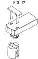
- FIG. 17 An example of a prior art connector employing a positive latching mechanism is shown in Figure 17.
- the connector of Figure 17 incorporates a separate locking piece having latching legs for insertion into the mated connector.
- the reliability of this configuration also suffers due to the possibility that an assembly operator may altogether forget to insert the locking piece into the mated connector or may likewise not fully insert the locking piece into a locking position.
- connection assembly for an airbag gas generator assembly that provides a positive latching mechanism with a two-piece connection assembly.
- the connection assembly should work automatically without requiring additional effort on the part of the assembly operator.
- connection assembly for an airbag gas generator.
- the connection assembly includes a connector having an independently rotatable latch, the prongs of which arcuately rotate about an elongate connector shaft that defines an expanse in which are supported a number of electrical contacts.
- Each prong is deflected under the bias of a spring projecting in like directions about the shaft from each prong.
- the free end of each prong also includes a hook projecting in like directions about the shaft opposite the longitudinal axis of the prong from the corresponding cantilever spring.
- Each hook includes a tapering undersurface contiguous with the free end of the prong and forming an acute angle with the longitudinal axis of the prong.
- Each tapering undersurface is contiguous with a hookface that runs substantially perpendicular to the longitudinal axis of the prong.
- the latch is spring-biased towards an undeflected position about the shaft.
- the socket connector includes a perimetrical wall defining a flag-shaped aperture for insertably receiving each prong of the latch.
- Each flag-shaped aperture includes a tab extending thereinto in flush alignment with the rim of the socket connector.
- the underside of each tab is a hookface in substantially uniform opposition to the hookface of the inserted latch.
- each tapering undersurface engages the rim at the tab
- each cantilever spring engages the rim at the opposing extent of the gap.
- Rotation of the latch in the locking direction positions the hookface of the latch opposite the hookface of the tab.
- the plug connector is thereby positively retained within the socket connector due to the interfering engagement between the hookfaces.
- the connectors cannot be disconnected by simply pulling the plug connector in a direction opposite to the insertion direction. First a tool is required to engage and rotate the latch in the deflection direction until latch hookface is no longer opposite the tab hookface and then the connector may be removed by pulling the connector in a direction opposite to the insertion direction.
- One embodiment of the present invention also provides a split ferrite shield within the body of the connector.
- Each of the leads of the connector are contiguous with the contacts of the connector shaft through an elongate channel formed between the two ferrite halves.
- An alternate embodiment of the present invention employs a conventional induction coil for shielding the connector.
- the present invention achieves the above-stated objectives utilizing a minimum of parts to facilitate the assembly of the connector.
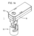
- Figure 1A shows the alignment of the plug connector and socket connector of the present invention.
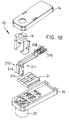
- Figure 1B shows an exploded view of the plug connector of the present invention.
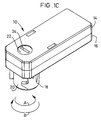
- Figure 1C shows the a isometric view of the plug connector of Figure 1A, showing the relationship between the cover, base, and latch.
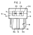
- Figure 2 shows a rear view of the plug connector of Figure 1A.
- Figure 3 shows the underside of the plug connector of Figure 1A, showing the relationship between the plug connector shaft, the plug connector contacts, the keying feature of the plug connector shaft, and the arcuate apertures for the latch prongs.
- Figure 4 is an isometric view of the interior expanse of the cover.
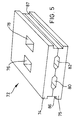
- Figure 5 is an isometric view of the ferrite assembly of the plug connector of the present invention.
- Figure 6 shows one of the symmetrical halves of the ferrite assembly of Figure 5.
- Figure 7 is an isometric view showing the interior expanse of the base of the plug connector of Figure 1A.
- Figure 8 is a top plan view of the interior expanse of the base of Figure 7.
- Figure 9 is an isometric view of the latch of the plug connector of Figure 1A.
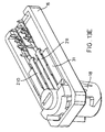
- Figure 10 is an isometric view of the contacts supported within the housing of the present invention.
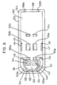
- FIG 11 is an isometric view of the socket connector of Figure 1.
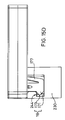
- Figure 12 is a elevational view of the socket connector of Figure 1.
- Figure 13A shows one of the symmetrical halves of the ferrite assembly of Figure 5 inserted in place in the interior expanse of the cover.
- Figure 13B shows the other symmetrical half of the ferrite assembly of Figure 6 inserted into the interior expanse of the housing of Figure 7.
- Figure 13C shows the contacts of Figure 10 inserted into the assembly of Figure 13B.
- Figure 13D shows the relative orientation of the assembly of Figure 13C and the latch of Figure 9 prior to inserting the latch therein.
- Figure 13E shows the assembly of Figure 13C with the latch of Figure 9 inserted therein.
- Figure 14 shows a partially exploded view of an alternate embodiment of a plug connector of the present invention.
- FIGS 15A-D depict the mating of the connector assembly of Figure 1.
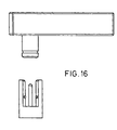
- Figure 16 shows an electrical connection assembly of the prior art.
- Figure 17 shows an electrical connection assembly of the prior art employing a separate member to provide positive latching.
- the present invention includes an electrical connector assembly 1 for providing connection between components of an airbag gas generator assembly.
- the connector assembly 1 comprises a male plug connector 10 and a female socket connector 12.
- plug connector 10 includes an electrically insulative housing 15 having a base 16, a cover 14, and a latch 18 for providing positive retentive interconnection with socket connector 12 of Figure 1A.
- Base 16 includes stationary shaft 20 extending from the underside thereof which has an outer surface that conforms to the interior surface of socket connector 12.
- Plug connector 10 supports electrical contacts 210, 211 therein. Electrical contacts 210, 211 are elongate right-angle contacts as are known in the art.
- Contacts 210, 211 include a cable terminating end 218, 219 providing a crimping wire connection for connecting to the conductors of a flat flexible cable leading to the airbag squib and an opposed interconnection end including a socket contact 214, 215 for accepting the contact pins 234, 235 of socket connector 12.
- Housing 15 includes ferrite assembly 72 (shown in full detail in Figure 5) formed of two symmetrical ferrites 74, 75 for shielding the electrical contacts 210, 211 passing therebetween in electrical isolation.
- Latch 18 is movably supported in housing 15 with limited freedom to rotate about stationary housing shaft 20.
- Latch 18 includes a pair of prongs 160, 161 which protrude through the underside of base 16 and provide for locking retention with socket connector 12.
- socket connector 12 includes an insulative female connector housing 230 which supports a pair of contact pins 234, 235 designed for interconnection with contacts 210, 211 of connector 10.
- housing 230 includes a pair of flag-shaped apertures 242, 243 which provide locking interconnection with the prongs 160, 161 of latch 18 when plug connector 10 is fully mated to socket connector 12.
- Disconnection of plug connector 10 from socket connector 12 requires that a tool, such as a screwdriver, be inserted into latch slot 24 and rotated in the direction of arrow A against the urging of cantilever arms 176, 177. Once hooks 170, 171 of prongs 160, 161 have been rotated clear of tabs 244, 245, plug connector 10 may be withdrawn from socket connector 12. Connection of the connector assembly therefore only requires plug connector 10 to be pushed into socket connector 12 in a single insertion direction. Disconnection of the connector assembly, however, requires, first, a tool to rotate latch 18 out of engagement with tabs 244, 245 of socket connector 12, and second, the withdrawal of plug connector 10 from socket connector 12 in a direction opposite to the insertion direction.
- a tool such as a screwdriver
- connector assembly 1 of the present invention Having provided a general overview of connector assembly 1 of the present invention, a more detailed description of the components of the preferred embodiment of the present invention follows.
- Figure 2 shows a rear view of plug connector 10.
- the interface between cover 14 and base 16 is seen to define a termination aperture 26 which provides access to termination end 218, 219 of contacts 210, 211.
- Behind termination ends 218, 219 is upper ferrite 74 and lower ferrite 75.
- Upper ferrite 74 and lower ferrite 75 provide a shielding function for plug connector 10 so as to prevent false signal generation associated with electromagnetic fields.
- Figure 2 also shows the longitudinal ridge 34 which provides a keying function with socket connector 12 to prevent malassembly of the connector assembly.
- FIG. 3 is a bottom view of plug connector 10 and more clearly illustrates keying surfaces 32a, 32b, and longitudinal ridge 34 of housing shaft 20.
- the keying function is contemplated to be provided by any of the methods known in the electrical connector art for ensuring assembly of two components in a single orientation.
- Housing shaft 20 defines shaft expanse 35 in which first socket 214 and second socket 215 are supported by base 16.
- first prong aperture 36 and second prong aperture 37 through which the prongs 160, 161 of latch 18 extend from base 16.
- first lower ferrite clip 46 and second lower ferrite clip 47 which are disposed within the interior of plug connector 10 and which are accessible through first lower clip aperture 48 and second lower clip aperture 49, respectively.
- lower ferrite clips 46 and 47 engage and hold lower ferrite 75 in the base 16.
- FIG 4 shows an internal view of cover 14.
- Cover 14 includes a cover floor 50 which is parametrically bounded by cover wall 52.
- Cover wall 52 includes first and second bowed surfaces 53a and 53b for accommodating latch 18 when plug connector 10 is assembled.
- Cover wall 52 terminates in cover rim 54.
- Cover wall 52 defines cover expanse 56 or the interior volume of cover 14.
- Cover 14 partially defines termination aperture 26 due to the provision of recessed rim 58 spanning between upper aperture extents 59a and 59b.
- the opposite end of cover 14 includes latch keyhole 60 which accommodates latch summit 22 as is shown in Figures 1A and 1B.
- Latch keyhole 60 is positioned to be concentric with the arcs of rotation through which prongs 160, 161 of latch 18 deflect.
- Cover expanse 56 includes successive pairs of downstands projecting from cover floor 50. As viewed from the position of the latch at keyhole 60, these downstands are seen to be first and second proximal downstand, 62, 63, first and second medial downstand, 64, 65, and first and second distal downstand, 66, 67 respectively.
- Figure 4 also shows second upper ferrite clip 69 which projects over second upper ferrite clip aperture 71 defined by wall 52 and floor 50.
- First upper ferrite clip 68 and first upper ferrite clip aperture 70 are hidden from view in Figure 4 and are located transversely across cover expanse 56 on cover wall 52.
- FIG. 5 shows ferrite assembly 72 which comprises upper ferrite 74 and lower ferrite 75 positioned in registry with each other.
- Ferrite assembly 72 includes first medial passage 76 and second medial passage 78 extending therethrough. Passages 76 and 78 correspond to the dimensions of first and second medial downstands 64 and 65.
- Ferrite assembly 72 also includes first lead channel 80 and second lead channel 82 extending longitudinally therethrough. Preferably, longitudinal indentations are formed in upper ferrite 74 and lower ferrite 75 and are placed in registry so as to form channels 80 and 82.
- Figure 6 shows lower ferrite 75.
- upper ferrite 74 and lower ferrite 75 are formed to be interchangeable and thereby facilitating the assembly of connector 10.
- lower ferrite 75 is simply characterized as a ferrite block having a pair of longitudinal grooves formed therein and a pair of through holes formed perpendicularly through the grooves.
- Each ferrite 74 and 75 is preferably formed to be symmetrical about a longitudinal and lateral axis so as to minimize the likelihood of improper assembly of connector 10.
- Each ferrite would therefore include apertures 76 and 78 for accommodating the first and second medial downstands of cover 14 or the corresponding first and second medial upstands of base 16, shown in Figure 7.
- Ferrite interface surfaces 88a, 88b, and 88c are coplanar and engage counterpart surfaces on upper ferrite 74.
- Lead channels 80 and 82 are partially defined by recessed surfaces 80a-c and 82a-c, respectively.
- ferrite 75 includes transversely spaced lower clip engagement surfaces 86 and 87 which are engaged by lower clips 46 and 47 respectively to hold lower ferrite 75 within the base 16. Surfaces 86 and 87 are equally capable of being retained by first and second upper ferrite clips 68, 69 of cover 14.
- FIG. 7 and 8 depict the base 16 of the present invention.
- Base 16 includes base floor 100 which is parametrically bounded by base wall 102.
- Base wall 102 includes first and second bowed surfaces 103a and 103b for accommodating the arcuate movement of latch 18 thereadjacent.
- Base wall 102 terminates in base rim 104 to thereby define base expanse 106.
- base wall 102 also includes recessed rim 108 spanning between lower aperture extents 109a and 109b to form the lower portion of termination aperture 26.
- Figure 7 and 8 show another view of first and second lower ferrite clips 46 and 47 and the first and second ferrite clip apertures 48 and 49 located along base wall 102.
- base floor 100 defines first prong aperture 36 and second prong aperture 37.
- First prong aperture 36 is defined adjacent to first bowed surface 103a of base wall 102 and convex rail surface 124.
- Latch rail 120 projects upward from base floor 100 adjacent prong apertures 36, 37.
- Latch rail 120 includes concave rail surface 122 and a convex rail surface 124 extending between first proximal upstand 112 and second proximal upstand 113.
- the second prong aperture 37 is defined between the second bowed surface 103b and convex rail surface 124.
- Latch rail 120 terminates at a rail rim surface 126 which supports latch 18 thereon.
- Rail 120 also defines rail notch 130 adjacent recessed rail rim 128.
- first cantilevered spring stop 132 and the second cantilevered spring stop 134 project radially outward from latch rail 120 adjacent latch apertures 36, 37, respectively.
- Concave rail surface 122 defines contact expanse 123 and communicates with first socket aperture 144 and second socket aperture 146 defined by base floor 100.
- first and second proximal upstands 112 and 113 first and second medial upstands 114 and 115, and first and second distal upstands 116 and 117, respectively.
- the uppermost surfaces of first proximal medial and distal upstands 112, 114 and 116 define aligned coplanar first contact strut support 150a, 150b and 150c, respectively.
- the upper extents of the second proximal medial and distal upstands 113, 115 and 117 define an aligned coplanar second contact strut support 151a, 151b and 151c, respectively.
- the strut supports 150a-c are longitudinally aligned between first socket aperture 144 and termination aperture 26 of the assembled plug connector 10. Likewise, the second contract strut supports 15 la-c are positioned between the second socket aperture 146 and termination aperture 26 of the assembled connector 10. Socket aperture 144 is also defined by socket rim 145. Socket aperture 146 is likewise partially defined by socket rim 147. Figure 8 more clearly shows the projection of first and second lower ferrite clips 46, 47 into base expanse 106 and the relation to first and second clip apertures 48, 49 respectively, defined by base floor 100 and base wall 102.
- FIG. 9 shows latch 18 of the present invention.
- latch 18 includes first and second latch prongs 160 and 161 positioned at opposing ends of latch brim 164.
- Latch brim 164 is seen to extend proximately halfway around the cylindrical outer surface of latch drum 166.
- Latch prongs 160, 161 are positioned in flush end relationship with the opposing ends of latch brim 164.
- Latch prongs 160,161 are also positioned in flush edge relationship with latch brim 164 to define latch shoulder 168.
- Latch drum 166 is formed to have a diameter to allow it to extend through keyhole aperture 60 of cover 14 to thereby making latch slot 24 accessible through cover 14.
- Latch tooth 190 depends from latch brim 164 and has an circumferential shape in conformance with brim 164. In the assembled condition, latch tooth 190 will be disposed in notch 130 of latch rail 120 and prevent over-rotation of latch 18.
- Each latch prong 160, 161 includes a latch hook 170, 171 rotationally aligned to one side of each prong and a cantilever spring arm 176, 177 rotationally aligned in opposition to latch hook 170, 171.
- Each hook 170, 171 includes a respective hookface 172, 173 and an opposed tapering undersurface 174, 175.
- Each latch cantilevered spring arm 176, 177 extends substantially along the length of their respective latch prongs 160,162 to form an elongate groove between each spring arm and its prong. Each spring arm terminates at a free end which is able to deflect towards its respective latch prong.
- Figure 10 shows first contact 210 and second contact 211 to be contained within connector 10.
- Contact 210 and contact 211 are preferably identically proportioned so as to enhance commonality during manufacture. It can been that contacts 210 and 211 include, respectively, an elongate contact strut 212, 213 with a socket contact 214, 215 depending downward therefrom at one end and termination end 218,219 depending from the opposing end. It is contemplated that each contact 210, 211 will include a flange 222, 223 projecting laterally outward therefrom in order to engage a surface of an upstand on which the contacts will be placed. Each socket contact 214, 215 is formed to receive the contact pins 234, 235 of socket connector 12 as is shown in Figure 1A.
- each termination end 218, 219 includes a plurality of upwardly projecting teeth 220, 221 to enhance the ability to engage the conductors of a flat flexible cable positioned therein.
- the manner of termination shown in Figure 10 is specifically employed in terminating flat flexible cable. It is also contemplated by the present invention that the particular manner of termination provided by termination end 218, 219 may be tailored to the particular type of cable to which connector 12 is to be mated. For example, a standard crimp design could be employed for connecting to conventional round stranded wire, whereas an insulation displacement termination such as is shown in Figure 14 could also be employed for round wire.
- socket connector 12 includes a female connector housing 230 having an open end 231 and defining a cavity 232. Housing 230 supports first and second electrical contact pins 234, 235 which extend into cavity 232 and which matingly electrically engage first and second socket contacts 210, 211 supported in housing shaft 20.
- Female connector housing 230 includes an internal cavity wall 238 having a shape conforming to the exterior surface of housing shaft 20. Contact pins 234, 235 are in electrical contiguity with other circuit components.
- Female connector housing 230 defines first and second flag-shaped apertures 242, 243 for insertably engaging and retaining first and second prongs 160, 161 of latch 18.
- Each flag-shaped aperture includes a tab 244, 245, respectively, protruding therein to define a first portion 246, 247 of flag-shaped aperture 242, 243 being proximal open end 231 and having a smaller circumferential expanse than a second portion 248, 249 of flag-shaped aperture 242, 243 distal from open end 231 of female connector housing 230.
- Tabs 244, 245 include a prong deflection element 250, 251 which engages the tapering undersurface 174, 175 of latch prong 160, 161 during insertion of housing shaft 20 into housing 230.
- Each tab 244, 245 also includes a hookface surface 254, 255 for opposing hookface surface 172, 173 of the prong 160, 161 once the connector housing 15 has been fully mated with female connection housing 230 and each prong has been deflected into the locked position.
- FIGS 13A-F depict a sequence for assembling plug connector 10 of the present invention.
- upper ferrite 74 is positioned within cover 14.
- First and second medial downstands 64, 65 are seen projecting through apertures 76, 78 of upper ferrite 74.
- the exposed faces of proximal downstands 62, 63, medial downstands 64,65 and distal downstands 66,67 extend to a height between that of interface surfaces 88a-c and channel surfaces 80b and 82b.
- clip 69 is shown to extend out over clip engagement surface 86.
- each of the upstands includes longitudinal tabs 154 extending above the plane of interface surface 88a-c. These longitudinal tabs 154 extend only so far above interface surface 88 so as to come into contact with the respective downstands of cover 14 while still allowing interface surfaces 88a-c of upper ferrite 74 and lower ferrite 75 to come into engagement as well.
- FIG. 13C shows each contact 210, 211 as assembled into the base 16.
- Each elongate strut 212, 213 rests upon its respective strut support 150a-c, 151a-c so as to be suspended above ferrite 75.
- each strut 212, 213 will likewise be suspended below upper ferrite 74 so as to prevent the possibility of short circuiting the contacts across the ferrite.
- Flanges 222 and 223 respectively abut against the tabs of distal upstands 116 and 117 oppositely from ferrite 72.
- socket contacts 214, 215 are disposed in their respective socket apertures 144 and 146 so as to be engagable by pins 234, 235 of socket connector 12.
- FIG. 13D shows latch 18 just prior to its insertion into base 16.
- Latch prongs 160 and 161 will be inserted through latch apertures 36 and 37 respectively.
- Each prong includes a latch detent 192 which provides a tapering surface 194 as its being inserting into base 16 and a flat abutment surface 196 which interfaces with base 16 so as to prevent the easy withdrawal of latch 18 back out from base 16.
- Latch 18 is positioned so that latch brim 164 sits atop rail rim surface 126 and latch tooth 190 is disposed within rail notch 130.
- latch 18 will be limited by a combination of the amount of travel provided tooth 190 in notch 130 and by the deflection of cantilevered spring arms 176 and 177 against spring stops 132 and 134 respectively.
- Cover 14, including upper ferrite 74, may then be positioned over the assembly shown in Figure 13E as is shown in Figure 1A.
- Figure 14 shows an alternate embodiment of the present invention where the shielding of contacts 210, 211 is provided by a wound wire coil 260. Wound wire coils are known in the art for their shielding capabilities. Figure 14 also illustrates one possible means for attaching cover 14 to base 16 by providing deflectable clips 264 which may be inserted over bulges 266 when cover 14 is placed on base 16. It is contemplated by the present invention that cover 14 may be attached or adhered to base 16 by any means known in the art for joining two components together.
- either pins or connectors may be mounted in either plug connector 10 or socket connector 12 or both so long as they provide mating electrical connection with the other component of the connector assembly of the present invention.
- prongs 160, 161 have been shown to reside exterior to shaft expanse 35, it is also contemplated by the present invention that the prongs may extend through expanse 35 and engage a female connector housing 230 that is insertably connected within shaft expanse 35.
- Such an embodiment provides a tamper-proof connection between housing 15 and socket connector 12 as prongs 160, 161 are not accessible to be deflected for disconnection except by a tool engaging latch slot 24 through cover 14.
- connector assembly 10 follows. As plug connector 10 is brought down upon socket connector 12, as shown in Figures 15A-C, tapering undersurface 174, 175 of latch hook 170, 171 comes into contact with prong engagement member 250, 251 of tab 244, 245. Housing shaft 20 is keyed to engage socket connector 12 in a single mating orientation. Continued insertion of plug connector 10 into socket connector 12 results in member 250, 251 pushing on latch hook undersurface 174, 175 so as to cause latch 18 to rotate about housing shaft 20 in the latch deflection direction represented by arrow A.
- latch 18 includes latch summit 22 which is accessible through cover 14.
- Latch summit 22 defines latch slot 24 which may be engaged by a tool such as a screwdriver, not shown, and turned in the deflection direction of arrow A so as to deflect cantilever spring arm 176, 177 until latch hook 170, 171 is clear of tab 240.
- a tool such as a screwdriver, not shown, and turned in the deflection direction of arrow A so as to deflect cantilever spring arm 176, 177 until latch hook 170, 171 is clear of tab 240.
- the worker may grab hold of plug connector 10 and withdraw it away from socket connector 12 to achieve disconnection.
Landscapes
- Details Of Connecting Devices For Male And Female Coupling (AREA)
- Air Bags (AREA)
Applications Claiming Priority (2)
| Application Number | Priority Date | Filing Date | Title |
|---|---|---|---|
| US1829096P | 1996-05-24 | 1996-05-24 | |
| US18290P | 1996-05-24 |
Publications (3)
| Publication Number | Publication Date |
|---|---|
| EP0808749A2 true EP0808749A2 (de) | 1997-11-26 |
| EP0808749A3 EP0808749A3 (de) | 1999-11-03 |
| EP0808749B1 EP0808749B1 (de) | 2003-03-12 |
Family
ID=21787194
Family Applications (1)
| Application Number | Title | Priority Date | Filing Date |
|---|---|---|---|
| EP97303558A Expired - Lifetime EP0808749B1 (de) | 1996-05-24 | 1997-05-23 | Steckverbindung für Gasgenerator |
Country Status (5)
| Country | Link |
|---|---|
| US (1) | US5895282A (de) |
| EP (1) | EP0808749B1 (de) |
| JP (1) | JP3451180B2 (de) |
| CA (1) | CA2205742C (de) |
| DE (1) | DE69719598T2 (de) |
Cited By (5)
| Publication number | Priority date | Publication date | Assignee | Title |
|---|---|---|---|---|
| WO1999006243A1 (en) * | 1997-07-31 | 1999-02-11 | The Whitaker Corporation | Squib connector |
| EP1009069A3 (de) * | 1998-12-07 | 2000-08-09 | Framatome Connectors International | Flachbau-Filterverbinder mit Ferrit |
| DE10025295A1 (de) * | 2000-05-22 | 2002-01-17 | Fci Automotive Deutschland Gmb | Steckverbinder, insbesondere für Airbag-Zündsysteme |
| US6435894B2 (en) | 1998-07-15 | 2002-08-20 | Tyco Electronics Logistics Ag | Connector for airbag gas generator |
| EP3396785A1 (de) * | 2017-04-27 | 2018-10-31 | Delphi International Operations Luxembourg S.à r.l. | Steckeranordnung |
Families Citing this family (32)
| Publication number | Priority date | Publication date | Assignee | Title |
|---|---|---|---|---|
| US6131947A (en) * | 1998-01-23 | 2000-10-17 | Trw Inc. | Electrical connector for air bag inflator |
| DE19935969C2 (de) * | 1999-07-30 | 2001-12-13 | Framatome Connectors Int | Kurzschluß-Kontaktträger für Zündersockel |
| JP3508016B2 (ja) * | 1999-12-24 | 2004-03-22 | 住友電装株式会社 | コネクタ |
| KR100564091B1 (ko) * | 2000-03-01 | 2006-03-27 | 니혼 앗사쿠단시세이조 가부시키가이샤 | 전기 접속 시스템 |
| US6390845B1 (en) * | 2001-01-10 | 2002-05-21 | M/A-Com Private Radio Systems, Inc. | Electrical connector for a portable radio |
| JP2003249308A (ja) * | 2002-02-25 | 2003-09-05 | Tyco Electronics Amp Kk | 電気コネクタ組立体 |
| US6799983B2 (en) | 2002-06-28 | 2004-10-05 | Amphenol-Tuchel Electronics Gmbh | Electrical connector with static discharge feature |
| US6837732B2 (en) * | 2002-06-28 | 2005-01-04 | Amphenol-Tuchel Electronics Gmbh | Filtered electrical connector with ferrite block combinations and filter assembly therefor |
| US20040192098A1 (en) * | 2002-06-28 | 2004-09-30 | Slobodan Pavlovic | Electrical connector with spring back/self rejection feature |
| US6767240B2 (en) * | 2002-06-28 | 2004-07-27 | Amphenol-Tuchel Electronics Gmbh | Electrical connector with cable insulation strain relief feature |
| WO2004004071A2 (en) * | 2002-06-28 | 2004-01-08 | Amphenol-Tuchel Electronics Gmbh | Electrical connector |
| US6705886B1 (en) | 2003-01-23 | 2004-03-16 | Fci Americas Technology, Inc. | Electrical connector having connector position assurance member |
| US6811424B2 (en) * | 2003-03-26 | 2004-11-02 | Fci Americas Technology, Inc. | Electrical connector having connector position assurance member |
| US6921279B2 (en) * | 2003-06-05 | 2005-07-26 | Fci Americas Technology, Inc. | Electrical connector with connector position assurance member |
| US6857892B2 (en) * | 2003-06-05 | 2005-02-22 | Fci Americas Technology, Inc. | Electrical connector with connector position assurance member |
| US6964579B2 (en) * | 2003-06-06 | 2005-11-15 | Fci Americas Technology, Inc. | Position assured connector |
| DE102004008712A1 (de) * | 2004-02-23 | 2005-09-08 | Tyco Electronics Amp Gmbh | Stecker |
| DE102004020933B3 (de) * | 2004-04-28 | 2005-12-29 | Tyco Electronics Amp Gmbh | Stecker, insbesondere Zündpillenstecker |
| DE102005021375B4 (de) * | 2005-05-04 | 2007-02-01 | Yazaki Europe Ltd., Hemel Hempstead | Steckverbinder, insbesondere für Airbag-Zündsysteme |
| JP4558619B2 (ja) * | 2005-09-30 | 2010-10-06 | 矢崎総業株式会社 | コネクタ |
| US8425254B2 (en) * | 2007-03-19 | 2013-04-23 | Fci Automotive Holding | Electrical connector with ferrite block assembly |
| US7354310B1 (en) * | 2007-06-07 | 2008-04-08 | Fci Americas Technology, Inc. | Electrical connector housing cover |
| JP5751194B2 (ja) * | 2011-09-08 | 2015-07-22 | 日立金属株式会社 | コネクタ及びワイヤハーネス |
| JP6177337B2 (ja) * | 2012-11-12 | 2017-08-09 | デルフィ・インターナショナル・オペレーションズ・ルクセンブルク・エス・アー・エール・エル | 自動二次ロックを備えたコネクタアセンブリ |
| JP2014110182A (ja) * | 2012-12-03 | 2014-06-12 | Jst Mfg Co Ltd | 電気コネクタ、およびスクイブの接続装置 |
| JP6537819B2 (ja) | 2014-12-18 | 2019-07-03 | 日本航空電子工業株式会社 | コネクタ対 |
| USD772231S1 (en) * | 2015-04-16 | 2016-11-22 | Physical Optics Corporation | Universal integrative mission module interface |
| JP6593631B2 (ja) * | 2015-09-24 | 2019-10-23 | 株式会社オートネットワーク技術研究所 | コネクタ |
| KR102633071B1 (ko) * | 2016-12-27 | 2024-02-05 | 한국단자공업 주식회사 | 벌브 오조립 방지용 벌브 홀더 |
| US10276948B1 (en) | 2018-06-13 | 2019-04-30 | Denso International America, Inc. | Battery connector for generator |
| IT201900002621A1 (it) * | 2019-02-22 | 2019-05-22 | Valentini S R L | Dispositivi di connessione elettrica comprendente mezzi di contattazione per il comando di un circuito ausiliario |
| CN112260001A (zh) * | 2020-10-19 | 2021-01-22 | 温州市乐伊汽车配件有限公司 | 一种具有高可靠性的汽车连接插拔端子 |
Family Cites Families (17)
| Publication number | Priority date | Publication date | Assignee | Title |
|---|---|---|---|---|
| US3869191A (en) * | 1973-10-11 | 1975-03-04 | Gen Motors Corp | Connector means having shorting clip |
| GB2063587B (en) * | 1979-11-16 | 1983-12-14 | Electronic Components Ltd | Snatch-type electrical connectors |
| US4380346A (en) * | 1981-04-24 | 1983-04-19 | Thiokol Corporation | Method of and apparatus for speeding the response of an air bag inflator at low temperatures |
| US4850888A (en) * | 1988-04-22 | 1989-07-25 | Amp Incorporated | Electrical connector with a deflectable shunt |
| JP2571310B2 (ja) * | 1990-12-14 | 1997-01-16 | 矢崎総業株式会社 | コネクタのロック保障機構 |
| DE4140692A1 (de) * | 1991-12-10 | 1993-06-17 | Trw Repa Gmbh | Elektrische steckverbindung an einem mit elektrischem zuender versehenen pyrotechnischen gasgenerator |
| US5275575A (en) * | 1992-10-09 | 1994-01-04 | Trw Inc. | Electrical connection system with safety interlock |
| GB9305758D0 (en) * | 1993-03-19 | 1993-05-05 | Amp Gmbh | Electrical connector having short circuiting facility |
| US5297976A (en) * | 1993-05-17 | 1994-03-29 | Electro-Wire Products, Inc. | Sealable electrical connector for an airbag sensor |
| US5401180A (en) * | 1993-06-01 | 1995-03-28 | Itt Corporation | Connector shorting spring |
| JPH0778657A (ja) * | 1993-09-07 | 1995-03-20 | Fujitsu Ltd | Emi防止フィルタの取付構造 |
| EP0650229A3 (de) * | 1993-10-22 | 1997-01-02 | Amphenol Tuchel Elect | Airbag Sicherheitssystem. |
| US5498164A (en) * | 1994-05-09 | 1996-03-12 | Ward; Mark C. | Automotive steering column electrical connector |
| US5528161A (en) * | 1994-09-15 | 1996-06-18 | Venturedyne Limited | Through-port load carrier and related test apparatus |
| US5458371A (en) * | 1994-10-27 | 1995-10-17 | Morton International, Inc. | Crimp-formed joint housings for air bag inflators |
| US5616045A (en) * | 1995-07-14 | 1997-04-01 | Augat Inc. | Squib connector for automotive air bag assembly |
| DE29514740U1 (de) * | 1995-09-15 | 1995-11-16 | Amphenol-Tuchel Electronics Gmbh, 74080 Heilbronn | Elektrischer Steckverbinder |
-
1997
- 1997-05-19 US US08/858,720 patent/US5895282A/en not_active Expired - Fee Related
- 1997-05-21 CA CA002205742A patent/CA2205742C/en not_active Expired - Fee Related
- 1997-05-23 EP EP97303558A patent/EP0808749B1/de not_active Expired - Lifetime
- 1997-05-23 DE DE69719598T patent/DE69719598T2/de not_active Expired - Lifetime
- 1997-05-26 JP JP13528697A patent/JP3451180B2/ja not_active Expired - Lifetime
Cited By (10)
| Publication number | Priority date | Publication date | Assignee | Title |
|---|---|---|---|---|
| WO1999006243A1 (en) * | 1997-07-31 | 1999-02-11 | The Whitaker Corporation | Squib connector |
| US6641424B1 (en) | 1997-07-31 | 2003-11-04 | Amp Of Great Britain Ltd. | Squib connector |
| US6435894B2 (en) | 1998-07-15 | 2002-08-20 | Tyco Electronics Logistics Ag | Connector for airbag gas generator |
| EP1009069A3 (de) * | 1998-12-07 | 2000-08-09 | Framatome Connectors International | Flachbau-Filterverbinder mit Ferrit |
| DE10025295A1 (de) * | 2000-05-22 | 2002-01-17 | Fci Automotive Deutschland Gmb | Steckverbinder, insbesondere für Airbag-Zündsysteme |
| DE10025295C2 (de) * | 2000-05-22 | 2002-10-31 | Fci Automotive Deutschland Gmb | Steckverbinder, insbesondere für Airbag-Zündsysteme |
| EP3396785A1 (de) * | 2017-04-27 | 2018-10-31 | Delphi International Operations Luxembourg S.à r.l. | Steckeranordnung |
| CN108808314A (zh) * | 2017-04-27 | 2018-11-13 | 德尔福国际业务卢森堡公司 | 连接器组件 |
| US10283905B2 (en) | 2017-04-27 | 2019-05-07 | Aptiv Technologies Limited | Electrical connector assembly |
| CN108808314B (zh) * | 2017-04-27 | 2020-04-03 | 德尔福国际业务卢森堡公司 | 气囊点火机构的电连接器组件 |
Also Published As
| Publication number | Publication date |
|---|---|
| DE69719598T2 (de) | 2003-12-11 |
| CA2205742C (en) | 2004-08-17 |
| CA2205742A1 (en) | 1997-11-24 |
| EP0808749B1 (de) | 2003-03-12 |
| JP3451180B2 (ja) | 2003-09-29 |
| EP0808749A3 (de) | 1999-11-03 |
| US5895282A (en) | 1999-04-20 |
| JPH1092517A (ja) | 1998-04-10 |
| DE69719598D1 (de) | 2003-04-17 |
Similar Documents
| Publication | Publication Date | Title |
|---|---|---|
| US5895282A (en) | Connector for airbag gas generator | |
| US6663411B2 (en) | Clamshell connector for airbag gas generator | |
| EP0869883B1 (de) | Richtungsfreie zündpille-anschlusseinrichtung für kraftfahrzeug-luftsacksysteme | |
| US6435894B2 (en) | Connector for airbag gas generator | |
| EP1150389B1 (de) | Steckverbinder mit Zweischalenteilen für Airbag Gasgenerator | |
| KR100282328B1 (ko) | 연동장치를가진전기접속시스템 | |
| EP0921600B1 (de) | Richtungsfreie Zündpille-Anschlusseinrichtung für Kraftfahrzeug-Luftsacksysteme | |
| JP2647336B2 (ja) | 電気接続装置 | |
| JP3165909B2 (ja) | 電気プラグコネクタ | |
| JP2887396B2 (ja) | 電気コネクタのラッチ機構 | |
| US5910028A (en) | Connector | |
| EP1091450B1 (de) | Verbinder | |
| US20090098758A1 (en) | Connection system and squib connector therefor | |
| CN111834788A (zh) | 带有端子锁的电端子壳体 | |
| EP1378973B1 (de) | Richtungsfreie Zündpille-Anschlusseinrichtung für Kraftfahrzeug-Luftsacksysteme | |
| MXPA98002792A (en) | Orientationless squib connector assembly for automotive air bag assemblies |
Legal Events
| Date | Code | Title | Description |
|---|---|---|---|
| PUAI | Public reference made under article 153(3) epc to a published international application that has entered the european phase |
Free format text: ORIGINAL CODE: 0009012 |
|
| AK | Designated contracting states |
Kind code of ref document: A2 Designated state(s): BE CH DE ES FR GB IT LI LU NL SE |
|
| PUAL | Search report despatched |
Free format text: ORIGINAL CODE: 0009013 |
|
| AK | Designated contracting states |
Kind code of ref document: A3 Designated state(s): BE CH DE ES FR GB IT LI LU NL SE |
|
| RIC1 | Information provided on ipc code assigned before grant |
Free format text: 6B 60R 16/02 A, 6H 01R 13/62 B, 6H 01R 13/625 B, 6H 01R 13/719 B |
|
| 17P | Request for examination filed |
Effective date: 20000420 |
|
| 17Q | First examination report despatched |
Effective date: 20011228 |
|
| GRAG | Despatch of communication of intention to grant |
Free format text: ORIGINAL CODE: EPIDOS AGRA |
|
| GRAH | Despatch of communication of intention to grant a patent |
Free format text: ORIGINAL CODE: EPIDOS IGRA |
|
| RAP1 | Party data changed (applicant data changed or rights of an application transferred) |
Owner name: THOMAS & BETTS CORPORATION |
|
| GRAH | Despatch of communication of intention to grant a patent |
Free format text: ORIGINAL CODE: EPIDOS IGRA |
|
| GRAG | Despatch of communication of intention to grant |
Free format text: ORIGINAL CODE: EPIDOS AGRA |
|
| GRAA | (expected) grant |
Free format text: ORIGINAL CODE: 0009210 |
|
| AK | Designated contracting states |
Designated state(s): BE CH DE ES FR GB IT LI LU NL SE |
|
| PG25 | Lapsed in a contracting state [announced via postgrant information from national office to epo] |
Ref country code: NL Free format text: LAPSE BECAUSE OF FAILURE TO SUBMIT A TRANSLATION OF THE DESCRIPTION OR TO PAY THE FEE WITHIN THE PRESCRIBED TIME-LIMIT Effective date: 20030312 Ref country code: LI Free format text: LAPSE BECAUSE OF FAILURE TO SUBMIT A TRANSLATION OF THE DESCRIPTION OR TO PAY THE FEE WITHIN THE PRESCRIBED TIME-LIMIT Effective date: 20030312 Ref country code: CH Free format text: LAPSE BECAUSE OF FAILURE TO SUBMIT A TRANSLATION OF THE DESCRIPTION OR TO PAY THE FEE WITHIN THE PRESCRIBED TIME-LIMIT Effective date: 20030312 Ref country code: BE Free format text: LAPSE BECAUSE OF FAILURE TO SUBMIT A TRANSLATION OF THE DESCRIPTION OR TO PAY THE FEE WITHIN THE PRESCRIBED TIME-LIMIT Effective date: 20030312 |
|
| REG | Reference to a national code |
Ref country code: GB Ref legal event code: FG4D |
|
| REG | Reference to a national code |
Ref country code: CH Ref legal event code: EP |
|
| REF | Corresponds to: |
Ref document number: 69719598 Country of ref document: DE Date of ref document: 20030417 Kind code of ref document: P |
|
| PG25 | Lapsed in a contracting state [announced via postgrant information from national office to epo] |
Ref country code: LU Free format text: LAPSE BECAUSE OF NON-PAYMENT OF DUE FEES Effective date: 20030523 |
|
| PG25 | Lapsed in a contracting state [announced via postgrant information from national office to epo] |
Ref country code: SE Free format text: LAPSE BECAUSE OF FAILURE TO SUBMIT A TRANSLATION OF THE DESCRIPTION OR TO PAY THE FEE WITHIN THE PRESCRIBED TIME-LIMIT Effective date: 20030612 |
|
| NLV1 | Nl: lapsed or annulled due to failure to fulfill the requirements of art. 29p and 29m of the patents act | ||
| REG | Reference to a national code |
Ref country code: CH Ref legal event code: PL |
|
| PG25 | Lapsed in a contracting state [announced via postgrant information from national office to epo] |
Ref country code: ES Free format text: LAPSE BECAUSE OF FAILURE TO SUBMIT A TRANSLATION OF THE DESCRIPTION OR TO PAY THE FEE WITHIN THE PRESCRIBED TIME-LIMIT Effective date: 20030930 |
|
| ET | Fr: translation filed | ||
| PLBE | No opposition filed within time limit |
Free format text: ORIGINAL CODE: 0009261 |
|
| STAA | Information on the status of an ep patent application or granted ep patent |
Free format text: STATUS: NO OPPOSITION FILED WITHIN TIME LIMIT |
|
| 26N | No opposition filed |
Effective date: 20031215 |
|
| PGFP | Annual fee paid to national office [announced via postgrant information from national office to epo] |
Ref country code: FR Payment date: 20100601 Year of fee payment: 14 |
|
| PGFP | Annual fee paid to national office [announced via postgrant information from national office to epo] |
Ref country code: IT Payment date: 20100526 Year of fee payment: 14 Ref country code: DE Payment date: 20100527 Year of fee payment: 14 |
|
| PGFP | Annual fee paid to national office [announced via postgrant information from national office to epo] |
Ref country code: GB Payment date: 20100525 Year of fee payment: 14 |
|
| REG | Reference to a national code |
Ref country code: DE Ref legal event code: R119 Ref document number: 69719598 Country of ref document: DE |
|
| REG | Reference to a national code |
Ref country code: DE Ref legal event code: R119 Ref document number: 69719598 Country of ref document: DE |
|
| GBPC | Gb: european patent ceased through non-payment of renewal fee |
Effective date: 20110523 |
|
| REG | Reference to a national code |
Ref country code: FR Ref legal event code: ST Effective date: 20120131 |
|
| PG25 | Lapsed in a contracting state [announced via postgrant information from national office to epo] |
Ref country code: IT Free format text: LAPSE BECAUSE OF NON-PAYMENT OF DUE FEES Effective date: 20110523 |
|
| PG25 | Lapsed in a contracting state [announced via postgrant information from national office to epo] |
Ref country code: FR Free format text: LAPSE BECAUSE OF NON-PAYMENT OF DUE FEES Effective date: 20110531 |
|
| PG25 | Lapsed in a contracting state [announced via postgrant information from national office to epo] |
Ref country code: GB Free format text: LAPSE BECAUSE OF NON-PAYMENT OF DUE FEES Effective date: 20110523 |
|
| PG25 | Lapsed in a contracting state [announced via postgrant information from national office to epo] |
Ref country code: DE Free format text: LAPSE BECAUSE OF NON-PAYMENT OF DUE FEES Effective date: 20111130 |