EP0808038A2 - Dispositif d'affichage avec illumination d'affichage adaptée à la luminosité - Google Patents
Dispositif d'affichage avec illumination d'affichage adaptée à la luminosité Download PDFInfo
- Publication number
- EP0808038A2 EP0808038A2 EP97107310A EP97107310A EP0808038A2 EP 0808038 A2 EP0808038 A2 EP 0808038A2 EP 97107310 A EP97107310 A EP 97107310A EP 97107310 A EP97107310 A EP 97107310A EP 0808038 A2 EP0808038 A2 EP 0808038A2
- Authority
- EP
- European Patent Office
- Prior art keywords
- receiver
- optical
- brightness
- ambient light
- display device
- Prior art date
- Legal status (The legal status is an assumption and is not a legal conclusion. Google has not performed a legal analysis and makes no representation as to the accuracy of the status listed.)
- Withdrawn
Links
Images
Classifications
-
- H—ELECTRICITY
- H04—ELECTRIC COMMUNICATION TECHNIQUE
- H04B—TRANSMISSION
- H04B10/00—Transmission systems employing electromagnetic waves other than radio-waves, e.g. infrared, visible or ultraviolet light, or employing corpuscular radiation, e.g. quantum communication
- H04B10/80—Optical aspects relating to the use of optical transmission for specific applications, not provided for in groups H04B10/03 - H04B10/70, e.g. optical power feeding or optical transmission through water
- H04B10/801—Optical aspects relating to the use of optical transmission for specific applications, not provided for in groups H04B10/03 - H04B10/70, e.g. optical power feeding or optical transmission through water using optical interconnects, e.g. light coupled isolators, circuit board interconnections
Definitions
- the invention relates to a display device with brightness adapted to the respective ambient light display lighting according to claim 1; such display devices, e.g. in the form of self-illuminating LED displays or backlit LCD displays are used for devices whose settings or operating states should be readable during the day and at night, but at night, i.e. with low ambient light, do not illuminate the room in an undesirable manner or use too much energy.
- display devices e.g. in the form of self-illuminating LED displays or backlit LCD displays are used for devices whose settings or operating states should be readable during the day and at night, but at night, i.e. with low ambient light, do not illuminate the room in an undesirable manner or use too much energy.
- Devices with display devices of the aforementioned type e.g. cookers with optoelectronic hob controls and corresponding illuminated operating mode displays
- optical interfaces by means of which data can be exchanged between an electronic device on the device on the one hand and one with, without the need for plug-in connection with the lines connected to it this electronics device communicating from the outside, for example in the form of a diagnostic or programming device, is possible.
- Such optical interfaces require a pair of optical transmitters and receivers for bidirectional transmission both for one and for the other electronic device, and for non-directional transmission at least one receiver in the device-side electronics and one transmitter in the diagnostic or programming device by means of which the data transmission can take place in at least one or in the other direction.
- Optical interfaces with data exchange between an external programming device and a unit to be programmed are e.g. known from DE-A1-39 21 344.
- the European patent application with the official file number 196 03 295.4 has already described an optoelectronic hotplate controller with an optical interface, via which a programming and / or a diagnostic unit can exchange data with a hotplate controller without the need for an electrical line or plug device.
- brightness-adapted display lighting can be achieved in a simple manner without an additional separate sensor for the respective ambient light; if alternating signals, in particular in the form of coded pulses, are used for the wireless data exchange of the optical interface, the measurement value for the respective brightness of the ambient light, which is usually present as a direct signal, can simultaneously be transmitted via the shared optical receiver of the interface and then by simple separation, for example by means of a low pass assigned to the constant light or a high pass assigned to the alternating signal, can be processed separately and in a targeted manner.
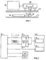
- FIG. 1 shows in the structural application configuration and FIG. 2 in a section in the associated block diagram an optical interface between an external programming and / or diagnostic unit DE above a radiation-permeable ceramic pane CE provided as a protective cover and a control unit MC in the form of a microcontroller below the ceramic pane - CE plate as part of an optoelectronic hotplate controller arranged and connected on a PL board.
- a first transmitter S1 and a first receiver E1 are used for optical transmission on the upper side of the ceramic disc CE and a second receiver E2 assigned to the first transmitter S1 and a second transmitter S2 assigned to the first receiver E1 are located below the ceramic disc CE.
- the second transmitter S2 and the second receiver E2 are connected to a serial interface output of the microcontroller, which a controller of this type, including the necessary test software, generally has.
- the signals of the mutual data exchange generally consist of specifically pulse-width-modulated pulse sequences which are transmitted without interference via the first transmitter S1 to the second receiver E2 by means of infrared radiation through the ceramic disc CE and lead to a specific command configuration in the microcontroller MC of the control unit; Corresponding feedback takes place via the second transmitter S2 by infrared radiation through the ceramic disc CE to the first receiver E1 and thus to the programming and / or diagnostic unit.
- an interface converter SW is provided on the external side between the first transmitter S1 and the first receiver E1, on the one hand, and the external programming and / or diagnostic unit DE, on the other hand, which converts the data from the programming and / or diagnostic unit DE Signals converted to so-called TTL levels.
- operating mode displays of an oven control are activated in a control front via illuminated displays, in particular via directly illuminated LED displays, illuminated setting displays of a hotplate control or by backlit LCD displays; the brightness of these displays should be adaptable to the respective ambient light.
- An optical measuring sensor must be provided for the necessary detection of the respective brightness of the ambient light;
- the second receiver E2 of the optical transmitter-receiver pair assumed to work in the range of visible light, of the hotplate controller assumed here is used for this purpose, as part of the optical interface with the transmitter-receiver pair S2; E2 or S1; E1 is installed.
- a parallel operation of the second shared receiver E2 is provided both for the data exchange of the optical interface, which is present per se, and for the acquisition of measured values of the ambient light
- an interface with a non-directional interface is of course also included in the invention if the receiver provided only on the hotplate interface side is also used as a transmitter for the brightness of the ambient light.
Landscapes
- Physics & Mathematics (AREA)
- Electromagnetism (AREA)
- Engineering & Computer Science (AREA)
- Computer Networks & Wireless Communication (AREA)
- Signal Processing (AREA)
- Optical Communication System (AREA)
- Control Of Indicators Other Than Cathode Ray Tubes (AREA)
- Fire-Detection Mechanisms (AREA)
- Investigating Or Analysing Materials By Optical Means (AREA)
Applications Claiming Priority (2)
| Application Number | Priority Date | Filing Date | Title |
|---|---|---|---|
| DE1996119926 DE19619926A1 (de) | 1996-05-17 | 1996-05-17 | Anzeigevorrichtung mit helligkeitsangepaßter Anzeigebeleuchtung |
| DE19619926 | 1996-05-17 |
Publications (2)
| Publication Number | Publication Date |
|---|---|
| EP0808038A2 true EP0808038A2 (fr) | 1997-11-19 |
| EP0808038A3 EP0808038A3 (fr) | 2001-11-07 |
Family
ID=7794578
Family Applications (1)
| Application Number | Title | Priority Date | Filing Date |
|---|---|---|---|
| EP97107310A Withdrawn EP0808038A3 (fr) | 1996-05-17 | 1997-05-02 | Dispositif d'affichage avec illumination d'affichage adaptée à la luminosité |
Country Status (2)
| Country | Link |
|---|---|
| EP (1) | EP0808038A3 (fr) |
| DE (1) | DE19619926A1 (fr) |
Cited By (1)
| Publication number | Priority date | Publication date | Assignee | Title |
|---|---|---|---|---|
| WO2001057561A1 (fr) * | 2000-02-01 | 2001-08-09 | Raytheon Company | Blindage d'un emetteur/recepteur de lumiere contre les rayonnements radioelectriques haute puissance |
Families Citing this family (3)
| Publication number | Priority date | Publication date | Assignee | Title |
|---|---|---|---|---|
| DE19727415A1 (de) * | 1997-06-27 | 1999-01-21 | Bosch Gmbh Robert | Schaltungsanordnung zur Ansteuerung einer Flüssigkristallanzeige |
| DE10126199A1 (de) * | 2001-05-30 | 2002-12-19 | Rational Ag | Gargerät mit Anzeigeeinheit |
| DE102011008616A1 (de) * | 2011-01-14 | 2012-07-19 | Conti Temic Microelectronic Gmbh | Verfahren zur Datenübermittlung |
Family Cites Families (6)
| Publication number | Priority date | Publication date | Assignee | Title |
|---|---|---|---|---|
| DE3909126C2 (de) * | 1989-03-20 | 1998-06-04 | Diehl Gmbh & Co | Schaltgerät für einen Kochherd |
| US5239295A (en) * | 1990-04-16 | 1993-08-24 | Motorola, Inc. | Serial light interface which also functions as an ambient light detector |
| DE4140647C2 (de) * | 1991-12-10 | 1996-09-12 | Bosch Gmbh Robert | Anzeigevorrichtung mit Lichtsensor |
| US5349162A (en) * | 1993-04-05 | 1994-09-20 | Whirlpool Corporation | Fault detection method and apparatus for a domestic appliance |
| US5473461A (en) * | 1994-08-26 | 1995-12-05 | Interactive Light, Inc. | Wide dynamic range optical receiver |
| DE9416779U1 (de) * | 1994-10-18 | 1994-12-08 | Bosch-Siemens Hausgeräte GmbH, 81669 München | Sensorgesteuerte Glaskeramik-Kochstelleneinheit |
-
1996
- 1996-05-17 DE DE1996119926 patent/DE19619926A1/de not_active Withdrawn
-
1997
- 1997-05-02 EP EP97107310A patent/EP0808038A3/fr not_active Withdrawn
Cited By (1)
| Publication number | Priority date | Publication date | Assignee | Title |
|---|---|---|---|---|
| WO2001057561A1 (fr) * | 2000-02-01 | 2001-08-09 | Raytheon Company | Blindage d'un emetteur/recepteur de lumiere contre les rayonnements radioelectriques haute puissance |
Also Published As
| Publication number | Publication date |
|---|---|
| EP0808038A3 (fr) | 2001-11-07 |
| DE19619926A1 (de) | 1997-11-20 |
Similar Documents
| Publication | Publication Date | Title |
|---|---|---|
| DE29917651U1 (de) | Meßumformer sowie Prozeßleitsystem | |
| EP4179393B1 (fr) | Anneau lumineux (rvb) sur un capteur à deux conducteurs | |
| WO2012004048A1 (fr) | Dispositif de mesure optoélectronique présentant une source lumineuse de compensation | |
| EP3417465B1 (fr) | Système de commande d'installations commandées électriquement | |
| EP0800059A1 (fr) | Procédé de transfert de données dans un dispositif de mesure de position | |
| DE102005025541A1 (de) | Steckdose und Anzeigesystem eines Gebäudes mit mehreren Steckdosen | |
| EP0811528B1 (fr) | Installation de commande | |
| EP1027227A1 (fr) | Dispositif pour influer sur un appareil d'eclairage | |
| DE102007055164B4 (de) | Leuchtmittel-Betriebsgerät zur Datenausgabe, System und elektronisches Vorschaltgerät mit einem derartigen Betriebsgerät | |
| EP0808038A2 (fr) | Dispositif d'affichage avec illumination d'affichage adaptée à la luminosité | |
| DE4419190C2 (de) | Sender bzw. Empfänger für ein Diagnosesystem | |
| DE3637689C1 (de) | Faseroptische Messwerterfassungs- und Uebertragungseinrichtung | |
| EP0664445A2 (fr) | Dispositif combiné pour déterminer la visibilité et la précipitation | |
| WO2018050425A1 (fr) | Appareil de terrain muni d'un élément de commande optoélectronique et procédé de détection d'un contact avec l'élément de commande | |
| CH704303B1 (de) | Fadenspannungssensor mit einstellbarem Nullpunkt und Messbereich. | |
| EP0808039A2 (fr) | Interface optique | |
| WO2017162483A1 (fr) | Appareil de terrain de la technique de l'automatisation | |
| DE19834122B4 (de) | Vorrichtung zur Parametrierung fertigungsbezogener Stellgrößen mittels drahtloser aktiv-infraroter Fernübertragung für Bewegungsmelder | |
| DE4427407B4 (de) | Diagnostische Schnittstelle für eine Induktionsschleife | |
| DE102022122176A1 (de) | Sensormodul | |
| DE102005043483A1 (de) | Automatisierungstechnische Einrichtung | |
| DE3738433A1 (de) | Steuersystem fuer ein kraftfahrzeug | |
| DE29507771U1 (de) | Meßwerteingabe- und Auswerteeinrichtung | |
| DE202007005787U1 (de) | Auslesevorrichtung für Steuerungseinrichtungen von Feuerungsautomaten | |
| WO2011124400A2 (fr) | Capteur pour un équipement d'éclairage |
Legal Events
| Date | Code | Title | Description |
|---|---|---|---|
| PUAI | Public reference made under article 153(3) epc to a published international application that has entered the european phase |
Free format text: ORIGINAL CODE: 0009012 |
|
| AK | Designated contracting states |
Kind code of ref document: A2 Designated state(s): DE ES FR GB IT |
|
| RAP1 | Party data changed (applicant data changed or rights of an application transferred) |
Owner name: BSH BOSCH UND SIEMENS HAUSGERAETE GMBH |
|
| PUAL | Search report despatched |
Free format text: ORIGINAL CODE: 0009013 |
|
| AK | Designated contracting states |
Kind code of ref document: A3 Designated state(s): DE ES FR GB IT |
|
| RIC1 | Information provided on ipc code assigned before grant |
Free format text: 7H 04B 10/10 A, 7F 24C 7/08 B, 7G 09G 3/34 B, 7H 05B 3/74 B |
|
| 17P | Request for examination filed |
Effective date: 20020507 |
|
| RAP1 | Party data changed (applicant data changed or rights of an application transferred) |
Owner name: BSH BOSCH UND SIEMENS HAUSGERAETE GMBH |
|
| STAA | Information on the status of an ep patent application or granted ep patent |
Free format text: STATUS: THE APPLICATION HAS BEEN WITHDRAWN |
|
| 18W | Application withdrawn |
Effective date: 20050425 |