EP3417465B1 - Système de commande d'installations commandées électriquement - Google Patents
Système de commande d'installations commandées électriquement Download PDFInfo
- Publication number
- EP3417465B1 EP3417465B1 EP17712915.2A EP17712915A EP3417465B1 EP 3417465 B1 EP3417465 B1 EP 3417465B1 EP 17712915 A EP17712915 A EP 17712915A EP 3417465 B1 EP3417465 B1 EP 3417465B1
- Authority
- EP
- European Patent Office
- Prior art keywords
- control device
- lighting
- switching element
- light intensity
- control system
- Prior art date
- Legal status (The legal status is an assumption and is not a legal conclusion. Google has not performed a legal analysis and makes no representation as to the accuracy of the status listed.)
- Active
Links
- 238000009434 installation Methods 0.000 title claims description 15
- 238000001514 detection method Methods 0.000 claims description 62
- 230000008878 coupling Effects 0.000 claims description 45
- 238000010168 coupling process Methods 0.000 claims description 45
- 238000005859 coupling reaction Methods 0.000 claims description 45
- 230000006978 adaptation Effects 0.000 claims description 32
- 230000000694 effects Effects 0.000 claims description 23
- 238000005516 engineering process Methods 0.000 claims description 20
- 230000011664 signaling Effects 0.000 claims description 20
- 238000012544 monitoring process Methods 0.000 claims description 9
- 230000003213 activating effect Effects 0.000 claims description 7
- 230000000737 periodic effect Effects 0.000 claims description 4
- 238000006073 displacement reaction Methods 0.000 claims 1
- 241000282414 Homo sapiens Species 0.000 description 12
- 238000004891 communication Methods 0.000 description 11
- 238000000034 method Methods 0.000 description 11
- 238000013461 design Methods 0.000 description 10
- 230000002950 deficient Effects 0.000 description 7
- 230000006870 function Effects 0.000 description 7
- 230000008569 process Effects 0.000 description 7
- 238000012360 testing method Methods 0.000 description 7
- 238000010422 painting Methods 0.000 description 5
- 238000012545 processing Methods 0.000 description 5
- 230000009471 action Effects 0.000 description 4
- 230000005540 biological transmission Effects 0.000 description 4
- 230000001419 dependent effect Effects 0.000 description 4
- 238000011161 development Methods 0.000 description 4
- 238000012546 transfer Methods 0.000 description 4
- 230000008901 benefit Effects 0.000 description 3
- 230000007547 defect Effects 0.000 description 3
- 238000005286 illumination Methods 0.000 description 3
- 230000001965 increasing effect Effects 0.000 description 3
- 238000012423 maintenance Methods 0.000 description 3
- 238000004519 manufacturing process Methods 0.000 description 3
- 238000005259 measurement Methods 0.000 description 3
- 230000003287 optical effect Effects 0.000 description 3
- 239000003973 paint Substances 0.000 description 3
- 230000001105 regulatory effect Effects 0.000 description 3
- 230000008439 repair process Effects 0.000 description 3
- 238000010521 absorption reaction Methods 0.000 description 2
- 230000033228 biological regulation Effects 0.000 description 2
- 230000004397 blinking Effects 0.000 description 2
- 238000004364 calculation method Methods 0.000 description 2
- 230000008859 change Effects 0.000 description 2
- 230000001276 controlling effect Effects 0.000 description 2
- 238000011990 functional testing Methods 0.000 description 2
- 230000004313 glare Effects 0.000 description 2
- 230000001976 improved effect Effects 0.000 description 2
- 230000033001 locomotion Effects 0.000 description 2
- 230000008447 perception Effects 0.000 description 2
- 230000009467 reduction Effects 0.000 description 2
- 238000005070 sampling Methods 0.000 description 2
- 230000008054 signal transmission Effects 0.000 description 2
- 239000000126 substance Substances 0.000 description 2
- 238000012935 Averaging Methods 0.000 description 1
- 206010034960 Photophobia Diseases 0.000 description 1
- 230000001133 acceleration Effects 0.000 description 1
- 230000004913 activation Effects 0.000 description 1
- 230000001154 acute effect Effects 0.000 description 1
- 238000000149 argon plasma sintering Methods 0.000 description 1
- 230000000903 blocking effect Effects 0.000 description 1
- 238000006243 chemical reaction Methods 0.000 description 1
- 239000011248 coating agent Substances 0.000 description 1
- 238000000576 coating method Methods 0.000 description 1
- 230000004456 color vision Effects 0.000 description 1
- 238000001816 cooling Methods 0.000 description 1
- 230000009849 deactivation Effects 0.000 description 1
- 230000006735 deficit Effects 0.000 description 1
- 238000005265 energy consumption Methods 0.000 description 1
- 230000004438 eyesight Effects 0.000 description 1
- 230000002349 favourable effect Effects 0.000 description 1
- 238000001914 filtration Methods 0.000 description 1
- 238000009499 grossing Methods 0.000 description 1
- 230000036541 health Effects 0.000 description 1
- 238000010438 heat treatment Methods 0.000 description 1
- 230000001939 inductive effect Effects 0.000 description 1
- 238000009776 industrial production Methods 0.000 description 1
- 230000010365 information processing Effects 0.000 description 1
- 230000010354 integration Effects 0.000 description 1
- 230000007774 longterm Effects 0.000 description 1
- 238000003754 machining Methods 0.000 description 1
- 230000007257 malfunction Effects 0.000 description 1
- 239000000463 material Substances 0.000 description 1
- QSHDDOUJBYECFT-UHFFFAOYSA-N mercury Chemical compound [Hg] QSHDDOUJBYECFT-UHFFFAOYSA-N 0.000 description 1
- 229910052754 neon Inorganic materials 0.000 description 1
- GKAOGPIIYCISHV-UHFFFAOYSA-N neon atom Chemical compound [Ne] GKAOGPIIYCISHV-UHFFFAOYSA-N 0.000 description 1
- 230000007935 neutral effect Effects 0.000 description 1
- 230000005855 radiation Effects 0.000 description 1
- 230000035945 sensitivity Effects 0.000 description 1
- 238000004904 shortening Methods 0.000 description 1
- 230000002123 temporal effect Effects 0.000 description 1
- 238000012549 training Methods 0.000 description 1
- 230000007704 transition Effects 0.000 description 1
- 238000012795 verification Methods 0.000 description 1
- 230000000007 visual effect Effects 0.000 description 1
Images


Classifications
-
- H—ELECTRICITY
- H01—ELECTRIC ELEMENTS
- H01H—ELECTRIC SWITCHES; RELAYS; SELECTORS; EMERGENCY PROTECTIVE DEVICES
- H01H3/00—Mechanisms for operating contacts
- H01H3/02—Operating parts, i.e. for operating driving mechanism by a mechanical force external to the switch
- H01H3/022—Emergency operating parts, e.g. for stop-switch in dangerous conditions
-
- E—FIXED CONSTRUCTIONS
- E04—BUILDING
- E04H—BUILDINGS OR LIKE STRUCTURES FOR PARTICULAR PURPOSES; SWIMMING OR SPLASH BATHS OR POOLS; MASTS; FENCING; TENTS OR CANOPIES, IN GENERAL
- E04H17/00—Fencing, e.g. fences, enclosures, corrals
- E04H17/14—Fences constructed of rigid elements, e.g. with additional wire fillings or with posts
- E04H17/1413—Post-and-rail fences, e.g. without vertical cross-members
- E04H17/1417—Post-and-rail fences, e.g. without vertical cross-members with vertical cross-members
- E04H17/1426—Picket fences
- E04H17/143—Picket fences with separate pickets attached to the side of the horizontal members
-
- H—ELECTRICITY
- H05—ELECTRIC TECHNIQUES NOT OTHERWISE PROVIDED FOR
- H05B—ELECTRIC HEATING; ELECTRIC LIGHT SOURCES NOT OTHERWISE PROVIDED FOR; CIRCUIT ARRANGEMENTS FOR ELECTRIC LIGHT SOURCES, IN GENERAL
- H05B47/00—Circuit arrangements for operating light sources in general, i.e. where the type of light source is not relevant
- H05B47/10—Controlling the light source
- H05B47/17—Operational modes, e.g. switching from manual to automatic mode or prohibiting specific operations
-
- E—FIXED CONSTRUCTIONS
- E04—BUILDING
- E04H—BUILDINGS OR LIKE STRUCTURES FOR PARTICULAR PURPOSES; SWIMMING OR SPLASH BATHS OR POOLS; MASTS; FENCING; TENTS OR CANOPIES, IN GENERAL
- E04H17/00—Fencing, e.g. fences, enclosures, corrals
- E04H17/14—Fences constructed of rigid elements, e.g. with additional wire fillings or with posts
- E04H17/1413—Post-and-rail fences, e.g. without vertical cross-members
- E04H17/1447—Details of connections between rails and posts
-
- F—MECHANICAL ENGINEERING; LIGHTING; HEATING; WEAPONS; BLASTING
- F16—ENGINEERING ELEMENTS AND UNITS; GENERAL MEASURES FOR PRODUCING AND MAINTAINING EFFECTIVE FUNCTIONING OF MACHINES OR INSTALLATIONS; THERMAL INSULATION IN GENERAL
- F16P—SAFETY DEVICES IN GENERAL; SAFETY DEVICES FOR PRESSES
- F16P3/00—Safety devices acting in conjunction with the control or operation of a machine; Control arrangements requiring the simultaneous use of two or more parts of the body
-
- G—PHYSICS
- G05—CONTROLLING; REGULATING
- G05B—CONTROL OR REGULATING SYSTEMS IN GENERAL; FUNCTIONAL ELEMENTS OF SUCH SYSTEMS; MONITORING OR TESTING ARRANGEMENTS FOR SUCH SYSTEMS OR ELEMENTS
- G05B9/00—Safety arrangements
- G05B9/02—Safety arrangements electric
-
- G—PHYSICS
- G08—SIGNALLING
- G08B—SIGNALLING OR CALLING SYSTEMS; ORDER TELEGRAPHS; ALARM SYSTEMS
- G08B5/00—Visible signalling systems, e.g. personal calling systems, remote indication of seats occupied
- G08B5/22—Visible signalling systems, e.g. personal calling systems, remote indication of seats occupied using electric transmission; using electromagnetic transmission
- G08B5/36—Visible signalling systems, e.g. personal calling systems, remote indication of seats occupied using electric transmission; using electromagnetic transmission using visible light sources
- G08B5/38—Visible signalling systems, e.g. personal calling systems, remote indication of seats occupied using electric transmission; using electromagnetic transmission using visible light sources using flashing light
-
- H—ELECTRICITY
- H01—ELECTRIC ELEMENTS
- H01H—ELECTRIC SWITCHES; RELAYS; SELECTORS; EMERGENCY PROTECTIVE DEVICES
- H01H71/00—Details of the protective switches or relays covered by groups H01H73/00 - H01H83/00
- H01H71/02—Housings; Casings; Bases; Mountings
-
- H—ELECTRICITY
- H01—ELECTRIC ELEMENTS
- H01H—ELECTRIC SWITCHES; RELAYS; SELECTORS; EMERGENCY PROTECTIVE DEVICES
- H01H71/00—Details of the protective switches or relays covered by groups H01H73/00 - H01H83/00
- H01H71/04—Means for indicating condition of the switching device
-
- H—ELECTRICITY
- H01—ELECTRIC ELEMENTS
- H01H—ELECTRIC SWITCHES; RELAYS; SELECTORS; EMERGENCY PROTECTIVE DEVICES
- H01H9/00—Details of switching devices, not covered by groups H01H1/00 - H01H7/00
- H01H9/16—Indicators for switching condition, e.g. "on" or "off"
- H01H9/161—Indicators for switching condition, e.g. "on" or "off" comprising light emitting elements
-
- H—ELECTRICITY
- H05—ELECTRIC TECHNIQUES NOT OTHERWISE PROVIDED FOR
- H05B—ELECTRIC HEATING; ELECTRIC LIGHT SOURCES NOT OTHERWISE PROVIDED FOR; CIRCUIT ARRANGEMENTS FOR ELECTRIC LIGHT SOURCES, IN GENERAL
- H05B47/00—Circuit arrangements for operating light sources in general, i.e. where the type of light source is not relevant
- H05B47/10—Controlling the light source
- H05B47/105—Controlling the light source in response to determined parameters
- H05B47/11—Controlling the light source in response to determined parameters by determining the brightness or colour temperature of ambient light
-
- Y—GENERAL TAGGING OF NEW TECHNOLOGICAL DEVELOPMENTS; GENERAL TAGGING OF CROSS-SECTIONAL TECHNOLOGIES SPANNING OVER SEVERAL SECTIONS OF THE IPC; TECHNICAL SUBJECTS COVERED BY FORMER USPC CROSS-REFERENCE ART COLLECTIONS [XRACs] AND DIGESTS
- Y02—TECHNOLOGIES OR APPLICATIONS FOR MITIGATION OR ADAPTATION AGAINST CLIMATE CHANGE
- Y02B—CLIMATE CHANGE MITIGATION TECHNOLOGIES RELATED TO BUILDINGS, e.g. HOUSING, HOUSE APPLIANCES OR RELATED END-USER APPLICATIONS
- Y02B20/00—Energy efficient lighting technologies, e.g. halogen lamps or gas discharge lamps
- Y02B20/40—Control techniques providing energy savings, e.g. smart controller or presence detection
Definitions
- the invention relates to a control system for electrically controlled systems.
- safety switching elements it is expedient and also common or prescribed to arrange manually operated safety switching elements in easily accessible and visible places in the vicinity or in the area of system components or machines or machine parts in order to enable operators to react as quickly as possible to dangerous situations in order to clearly end a dangerous situation .
- a system or system component or machine can be put into a safe state.
- a transfer to a safe state or operating state can be achieved, for example, by switching off drive devices or actuators, interrupting the energy supply, activating braking devices or similar measures.
- Such safety switching elements include, for example, the known mushroom-shaped emergency stop or emergency stop switches.
- specific, colored markings are proposed in the relevant standards, or in many cases are prescribed.
- an emergency stop switch is also clearly recognizable or familiar to people who are not specifically trained to operate a system or system component, and an emergency stop switch marked in a corresponding color, as well as its effect.
- mobile or transportable operating devices are often used for processes or tasks which require the manual input of control commands by a human operator.
- Such mobile handheld operating devices allow an operator a certain degree of mobility in the area of a system or machine.
- the advantage here is that the operator can take a suitable or favorable observation position in the area of a machine during manual operation.
- such mobile handheld operating devices for the provision or transmission of data, signals and control commands can be connected to one or more functional control devices of an electrically controllable system and / or system component via wired or wireless communication links.
- the input of control commands on such a handheld control unit can be transmitted via appropriate communication links to a control device, which control device then immediately converts the transmitted or provided control commands into corresponding control signals for actuators, drives, heating or cooling means, or other electrically controllable ones Implements machine components.
- at least one safety switching element for example in the form of an emergency stop or emergency stop switch, is also provided on a hand-held control device.
- a communication connection for the transmission or provision of manually entered control commands can therefore be canceled, for example by unplugging a corresponding cable connection or by interrupting a corresponding wireless radio connection or by canceling a data link in a communication network.
- This also prevents potential dangers from possible incorrect operation, for example if an operator inadvertently actuates an input element to trigger a control command on the hand-held operating device without being in the vicinity of the corresponding system component or machine.
- Illuminated emergency stop switches with translucent or semitransparent lateral surfaces are known from the prior art, in which the corresponding emergency stop switch is colored by the emergency stop switch associated with lighting means integrated in the emergency stop switch is identified.
- the corresponding emergency stop switch is colored by the emergency stop switch associated with lighting means integrated in the emergency stop switch is identified.
- the corresponding lighting means are activated when a handheld control unit is plugged in or coupled, whereas the light sources are deactivated when the handheld control unit is disconnected or in the case of de-energized handheld control units.
- the emergency stop switch that is not illuminated appears in a neutral color code, for example milky gray or white.
- the object of the invention was to solve the existing problems and to provide an improved control system by means of which, in particular, the ambient brightness-dependent perception of actively illuminated safety switching elements by human beings is taken into account.
- a control system for electrically controlled systems comprises at least one control device for monitoring and / or controlling the system and / or system components.
- control system comprises at least one portable, mobile handheld control device for displaying information and for inputting control commands by an operator, the handheld control device having at least one manually operable safety switching element, to which a lighting device with at least one lamp is assigned.
- the control system also includes a couplable and detachable signal connection between the safety switching element of the handheld control unit and the at least one control device or a separately designed safety controller, the control system in the presence of a coupled signal connection and manual actuation of the safety switching element for transferring the system or one or more system components into one safe state is formed, and wherein the control system is formed in the presence of a coupled signal connection to activate the lighting device, and in the presence of a released signal connection is formed to deactivate the lighting device.
- control system comprises at least one lighting control device which, when there is a coupled signal connection between the safety switching element of the hand-held control device and the at least one control device or the safety controller, is designed for the electrically and / or electronically controlled adjustment of a visually perceptible light intensity of the lighting device.
- control system comprises several lighting control devices, each of which is designed to adapt the visually perceptible light intensity of the lighting device of the handheld device after a coupling or production of a signal connection between the safety switching element of a handheld device and a control device of the control system.
- the specified features provide a technical means by which the visually perceptible light intensity of a safety switching element can be fundamentally changed, and in particular the visually perceptible light intensity can be adapted to the prevailing light conditions or to a respective ambient brightness. This can also ensure that the color coding of the safety switching element can be reliably perceived by human persons, in particular operators, when the coupled signal connection is present between the safety switching element and the at least one control device.
- an illuminated safety switching element is poorly or no longer recognizable as functionally effective in high ambient brightness, for example in well-lit workplaces or in strong sunlight.
- the signal connection between the at least one safety switching element of the hand-held operating device and the at least one control device can in principle be implemented either in a wired or wireless manner.
- the specified features enable energy-efficient operation, especially of battery-operated handheld devices.
- the energy consumption can also be limited to a necessary level and thus the battery life or battery life can be reduced.
- the functional runtime of the hand-held control device can advantageously be increased.
- At least one manually adjustable input setting means is functionally assigned to the at least one lighting control device, the lighting control device for electrical and / or electrical purposes when there is a coupled signal connection between the safety switching element and the at least one control device and when the input setting means is adjusted by an operator electronically controlled adaptation of the visually perceptible light intensity of the lighting device is formed on the basis of the respective position of the input setting means.
- the at least one lighting control device is designed for the electrically and / or electronically controlled adaptation of the visually perceptible light intensity of the lighting device within a restricted range between a control-technically specifiable, minimum limit intensity and a control-technically specifiable, maximum limit intensity.
- the minimum limit intensity allows a visually perceptible minimum luminous intensity to be specified, by means of which a functionally effective safety switching element is made possible for an expected ambient brightness in the area of a certain system component or at a certain workstation.
- a maximum adjustable, visually perceptible light intensity can be specified, by means of which the light intensity can be limited for lighting-sensitive workplaces, such as paint shops or the like.
- the respective minimum and / or maximum limit intensities can be adapted accordingly in the case of extensive systems with different ambient light levels in the area of the system components. In this way, a manual adjustment or adaptation of the visually perceptible light intensity by an operator is only possible in the restricted area, whereby, for example, unsuitable or incorrect or too low or too high light intensity settings can be prevented. In particular, damage or a shortening of the service life of the lamp (s) of the lighting device can be prevented by setting too high visually perceptible luminous intensities.
- At least one detection means is provided for monitoring user activities, which detection means is designed to signal a detected presence or a detected non-presence of user activities with respect to the at least one lighting control device.
- This provides a means by means of which it can be determined whether a hand-held control device is being used or not. By providing or signaling this information to the lighting control device, the adaptation of the light intensity of the lighting device can be adapted accordingly.
- an embodiment can be useful in which the at least one lighting control device is present when a coupled signal connection is present and when a signaling of the presence of user activities for the electrically and / or electronically controlled adjustment of the visually perceptible light intensity to a first, low level, and if there is a coupled signal connection and if there is a signaling of the absence of user activities for the electrically and / or electronically controlled adjustment of the visually perceptible light intensity is formed on a second, higher level compared to the first level.
- the visually perceived light intensity of the lighting device or of the at least one safety switching element can be reduced when an operator carries out operating or monitoring tasks by means of the hand-held operating device.
- both the ease of use and the operational safety and reliability can be improved; in particular, working without glare can be made possible by a safety switching element illuminated with too high a luminous intensity with the hand-held control device.
- the lighting control device can be used to increase the light intensity of the lighting device and thus the light intensity of the safety switching element in order to make the safety switching element recognizable even for people at a greater distance from the hand-held control device and thus easy to find in an emergency.
- control system it can be provided that it comprises at least one machine-side coupling counterpart, which is locally assigned to an electrically controllable system component, the at least one coupling counterpart at least for establishing and releasing the signal connection between the at least one safety switching element of the hand-held control device and a control device of the system and / or system component is formed.
- a manual control device or its safety switching element can be assigned to different system components.
- different lighting conditions or ambient brightness in the local area of the various system components can be taken into account in the course of planning the security measures.
- an intuitive and easy-to-mix-up option for coupling a hand-held control device is provided for an operator.
- the at least one remote coupling point can be assigned an identifier, which identifier has data technology information with regard to a minimum limit intensity and / or an optimal level for the visually perceptible light intensity in the area of the assigned system component, and the at least one lighting control device for direct detection the identifier or for the indirect detection of the identifier via an identifier detection means, and for the electrically or electronically controlled adaptation of the visually perceptible light intensity on the basis of the data-technical information of the identifier.
- This embodiment makes it possible to provide information for the adaptation of the light intensity of the lighting device for the at least one lighting control device, which takes into account the ambient brightness conditions to be expected in the area of the relevant system component.
- the identifier can be stored, for example, as a data record in a memory element of the coupling counterpart, and can be read out by the at least one lighting control device when the hand-held control device is coupled.
- an identifier can also be stored directly in a memory element of a lighting control device itself, and thus be provided directly for the at least one lighting control device.
- an identifier detection means to detect an identifier configured to be detectable by sensors, for example by a sensor configured on the hand-held control device.
- the light intensity of the lighting device can be adapted accordingly by the lighting control device.
- the identifier can have at least one piece of data technology information about a minimum required level for the light intensity or a minimum limit intensity at a respective coupling counterpart or a system component assigned to a coupling counterpart, as well as at least one data technology information about an optimal level for the visually perceptible light intensity in the area of the provide corresponding system components for the at least one lighting control device.
- the at least one lighting control device comprises at least one first switching device, and the lighting control device is designed to activate or deactivate the lighting device by switching the first switching device to an electrically conductive or an electrically non-conductive switching state.
- This embodiment variant allows the lighting device to be switched on and off efficiently by switching on or switching off or interrupting an energy supply for the lighting device.
- the at least one lighting control device can be designed for the variable adaptation of the energy supply for the lighting device.
- the lighting control device can be designed to supply the lighting device with electrical current with a variable voltage and / or variable current intensity. In this way, a variable adaptation of the visually perceptible light intensity of the lighting device is subsequently made possible.
- the at least one lighting control device can also be expedient for the at least one lighting control device to be designed for the electrically and / or electronically controlled adaptation of the visually perceptible light intensity of the lighting device by applying a pulse-width-modulated control signal to the first switching means.
- This embodiment variant allows simple but nevertheless efficient control of the lighting device or its visually perceptible light intensity in terms of circuitry.
- the visually perceptible light intensity can be regulated or specified by the lighting control device by varying the pulse-pause ratio of the pulse-width-modulated control signal.
- the visually perceptible light intensity can be reduced, the visually perceived or felt light intensity of the lighting device or the safety switching element resulting from the inertia of the human eye.
- the duration is sufficiently short and the duration is sufficiently short, it becomes more consecutive to a human eye Sequence or clock frequency of the pulse intervals and the pause intervals, only the average luminous intensity perceived, as is known per se.
- a pulse-width-modulated activation signal By activating or regulating the lighting device via a pulse-width-modulated activation signal, a high degree of energy efficiency can also be achieved for the lighting device (s) of the lighting device.
- the at least one lighting control device for activating or deactivating the lighting device comprises a second, switchable switching means, which second switching means is electrically connected in series with the first switching means.
- the lighting device can be reliably switched off by interrupting its power supply by means of the respective other switching means. This also minimizes the risk of incorrect or misleading signaling of functional effectiveness of the safety switching element.
- a pulse-width-modulated control signal from the lighting control device can of course also be applied to the second switching means.
- the at least one lighting control device can also be expedient for the at least one lighting control device to be assigned at least one checking means for checking the line state or switching state of the switching means (s), and the lighting control device, if the lighting device is in a deactivated state, for checking the proper, non-conducting state the switching means is formed by means of the at least one checking means.
- the checking means can be formed, for example, by a current measuring means which is designed to monitor a non-conductive state of the energy supply line for the lighting device is.
- the checking means can also be formed by a light-detecting sensor assigned to the lighting device or the safety switching element, which sensor is designed to detect a deactivated, that is to say non-luminous, lighting device.
- the at least one lighting control device is designed to execute a test cycle, which test cycle alternately comprises switching one of the switching means into a non-conductive state and the simultaneous switching of the other switching means into a conducting state in a periodic sequence .
- each of the switching means can be checked cyclically by means of the checking means. Individual faults can thus be reliably detected before a loss of safety can occur due to another defective switching device.
- the at least one lighting control device can subsequently be designed to display or signal a detected fault, for example a defective switching means.
- the at least one lighting control device is assigned a signal connection status checking means for signaling purposes, which signal connection status checking means is designed to continuously check the coupling status of the signal connection, and that the lighting control device is designed to activate the lighting device in the event of a coupled status of the signal connection, and in the In the event of a released state of the signal connection for deactivating the lighting device is formed.
- the coupling status of the signal connection between the safety switching element of the hand-held control device and the at least one control device can be continuously monitored by the lighting control device by means of the signal connection status checking means.
- the lighting control device can also automatically activate or deactivate the lighting device as a function of the detected coupling state of the signal connection.
- the at least one lighting control device is structurally arranged in the counterpart coupling on the machine side.
- This embodiment is particularly useful when the signal connection between the at least one safety switching element of the hand-held operating device and the at least one control device is wired.
- the signal connection can be designed as a wired safety circuit.
- This configuration of the control system can advantageously minimize the structural complexity of the hand-held operating devices.
- the structural arrangement of the at least one lighting control device in the coupling counterpart also represents a particularly safe embodiment for moving the lighting control device.
- each coupling counterpart of the control system or only some of the existing coupling counterparts can each have a lighting control device.
- the at least one lighting control device is structurally arranged in the hand-held operating device.
- This embodiment variant is particularly advantageous when using signal connections that can be coupled wirelessly or wirelessly between the safety switching element and the at least one control device. This is also because in such cases the energy or power supply for the lighting device, which is varied electrically or electronically by the lighting control device to adapt the visually perceptible light intensity, is fed by an electrical power source also arranged on the hand-held control unit.
- the at least one lighting control device is equipped with at least one first, light intensity-sensitive Sensor means is connected in terms of data signals, which first sensor means is structurally arranged in a vicinity of the safety switching element or within the safety switching element, and which sensor means is designed to detect the ambient brightness in the vicinity of the safety switching element.
- an efficient detection means for detecting the current ambient brightness can be provided for a lighting control device, and not only general information is provided about the ambient brightness at a workplace.
- Such a sensor means also changes in the ambient brightness can be detected, which can result, for example, from a change in the position or location of the hand-held control device, for example by moving the hand-held control device into areas of a system component that is shaded by machine parts or components, or, for example, by covering the safety switching element and the same.
- the at least one lighting control device is designed for the automatic, electrically or electronically controlled adaptation of the visually perceptible light intensity of the lighting device on the basis of the detected ambient brightness, and / or for the automatic, dynamic specification of a minimum limit intensity for the lighting device Is formed based on the detected ambient brightness.
- This provides a means for automatically adapting or regulating the visually perceptible light intensity when the ambient brightness changes.
- a visually perceptible light intensity that is as optimal as possible can be set, or at least a minimum required limit intensity can be set automatically. This can ensure that a functionally effective safety switching element can also be recognized as functionally effective with high reliability.
- control system comprises at least one light source assigned locally to a system component, which light source is designed to emit a coded light signal, and that the first luminous intensity-sensitive sensor means for detection and provision to the lighting control device of the coded Light signal of the light source is formed.
- coded light signals can be detected by means of the first sensor means and can be used with respect to the lighting control device for further information processing and / or information forwarding.
- the lighting control device is designed to provide information about the detection of a coded light signal to a control device and / or a safety controller, and that the respective control device and / or safety controller to release at least observation-relevant control commands only in the event of a provision information about detection of a coded light signal by the lighting control device is formed.
- the environment of a certain machine or system component can be illuminated with a light signal with a system-specific coding.
- certain operating commands in particular control commands relevant to observation, can only be executed as long as the operator is at least within sight of the respective system component or machine and can visually detect and monitor the effect of their operator actions.
- this can be advantageous for safe operation of a system.
- the coded light signal can also be transmitted and evaluated in the course of setting up a radio link between a wirelessly coupled handheld control device and a control device of the system or system component. This also enables confusion-proof assignment of a hand-held control device.
- the at least one lighting control device is wired for data signal technology to a second, luminous intensity-sensitive sensor means, which second sensor means is structurally arranged in the vicinity of the safety switching element or within the safety switching element, and which second sensor means is used to detect an actual value of the luminous intensity of the lighting device is trained.
- this second sensor means can be used to check whether the lighting device is basically functioning.
- a sensor means can effectively improve the operational reliability of the control system.
- the at least one lighting control device is designed to compare the detected actual value of the lighting intensity of the lighting device with an internally defined and / or control-generated setpoint for the lighting intensity, and that the lighting control device is based on the comparison when it is determined that a defined limit value is exceeded is designed for a permissible deviation of the actual value from the target value for providing a target value error signal to a control device and / or a safety controller of the control system.
- a detected fault or a faulty function of the lighting device or the control electronics for the lighting device can be displayed immediately.
- a repair or maintenance measure can be initiated immediately, for example, and the operational reliability of the control system can be maintained.
- the at least one lighting control device is designed to adapt the visually perceptible light intensity by applying a pulse-width-modulated control signal to the lighting device
- the second sensor means is designed to detect and provide for the lighting control device a time curve of the pulse-width-modulated light emitted by the lighting device
- the lighting control device is designed to check the proper functioning of the lighting device by comparing a sensor signal of the second detected during a pulse time interval of the pulse-width-modulated control signal
- Sensor means is designed with a sensor signal of the second sensor means detected during a pause time interval of the pulse-width-modulated control signal
- the lighting control device is designed to provide a pulse-pause error signal to a control device and / or a safety controller of the control system in the event of a negative check result.
- a means for checking the pulse-width-modulated control signal for the lighting device is provided for the at least one lighting control device.
- it can be checked for the lighting control device whether the pulse-width-modulated control signal is also reflected with sufficient amplitude in the temporal course of the time-resolved, pulse-width-modulated light of the lighting device or of the lighting means of the lighting device.
- the specified features provide a continuous functional test of both the lighting device and the second sensor means and the switching means (s). For example, switching errors in the control of the lighting device, which can manifest themselves through constant lighting of the lighting device, can be detected in this way. Such errors can be caused, for example, by defective electronic switching means.
- the at least one lighting control device is designed to compare the sensor data provided by the first sensor means and / or the second sensor means with reference data that can be stored in the control system, and that the lighting control device can be used if a permissible deviation of the sensor data from the reference data is exceeded Providing a deviation error signal to a control device and / or a safety controller of the control system is formed.
- the at least one lighting control device can be designed, for example, to block the input of control commands or to not implement control commands entered on the hand-held operating device concerned.
- the at least one lighting control device comprises a current measuring means for determining the electrical current flow recorded by the lighting device, and that the lighting control device is designed to compare the recorded current flow data with reference data stored in the control system, and that the lighting control device if exceeded a predetermined deviation of the specific current flow data from the reference data is designed to provide a current flow error signal to a control device and / or a safety controller of the control system.
- the lighting control device By detecting the current flow, defects in electronic switching means and lines as well as defective lighting means of the lighting device can in particular be detected efficiently by the lighting control device. As a result of the error signaling, the lighting control device can in turn display such an error immediately.
- control device and / or the safety control is designed to immediately transfer the system or the affected system component to a safe state when an error signal is provided by the lighting control device.
- an error signal for example a setpoint error signal, deviation error signal, pulse-pause error signal and / or a current flow error signal
- a reduction or loss of operational reliability can be immediately halted or prevented in this way.
- the system or an affected system component or machine can be immediately put into a safe state and kept until, for example, a defective safety switching element or a defective lighting device is repaired or is ready for operation again, or for example a full one, by means of a correspondingly designed control system functional hand-held device with functioning or functioning safety switching element (s) is coupled instead of the defective hand-held device.
- control device and / or the safety controller is designed for the signaling coupling of an error signal in a signal-equivalent manner to a manually operated safety switching element in a safety circuit for the system or the system component.
- This provides a safe and reliable means for transferring a system or system component into a safe state when an error signal is provided by the lighting control device, that is to say an error is reported.
- control device and / or the safety control is designed to block safety-relevant control commands and / or to display the error signal or the error signals when an error signal is provided by the lighting control device.
- the blocking of control commands is an effective safety measure to prevent the triggering of control commands via the handheld device concerned in the event of a defect in a safety switching element or lighting device for a safety switching element, so that a fully functional handheld device must be used for this purpose.
- the at least one lighting control device is designed to compare the detected actual value of the light intensity of the lighting device with an internally defined and / or control-generated setpoint for the light intensity, and that the lighting control device is designed on the basis of the comparison to the electrical and / or electronic readjustment of the visually perceptible light intensity of the lighting device is formed.
- This embodiment variant allows changes in the light intensity generated by the lighting device to be recorded and corrected.
- long-term deviations for example an age-related reduction in the light intensity of the light source (s) of the lighting device, can be detected and corrected accordingly by the lighting control device.
- first and second sensor means when using a first and second sensor means, a continuous functional test of the two sensor means can be carried out. If a first and a second sensor means are used together, a mutual or reciprocal influence between the detection of the lighting of the safety switching element and in particular the detection of a coded work area illumination can be easily compensated for by calculation. This also applies when the visually perceptible light intensity is adjusted by applying a pulse-width-modulated control signal to the lighting control device.
- the first sensor means and the second sensor means have a common intensity detection element, and the at least one lighting control device is designed to periodically query the intensity detection element during pulse time intervals and pause time intervals of a pulse-width-modulated control signal for the lighting device.
- the lighting control device is designed to use a pulse-width-modulated control signal for adjusting the light intensity of the lighting device, this technical feature allows both the light intensity of the lighting device and the ambient brightness to be detected in principle by means of a single intensity detection element.
- the information about luminous intensity and ambient brightness is mapped in the course of time of the pulse and pause phases of the light emitted by the lighting device, which are detected by means of the intensity detection element.
- this design variant represents a structurally simple and space-saving implementation for the detection of both the light intensity and the ambient brightness.
- the at least one lighting control device is designed to determine the ambient brightness from the sensor data interrogated during pause time intervals.
- the precise detection of the ambient brightness is possible through this feature of the lighting control device regardless of whether the lighting device is activated or deactivated, that is to say can be perceived as being illuminated or not. Disturbances in the measurement of the ambient brightness are thus prevented by a lighting device that is basically activated. As a further consequence, disturbances in the ambient brightness-dependent, electronic adjustment of the visually perceptible light intensity can be prevented, since the ambient brightness is determined or recorded by the lighting control device only in the pause phases or pause time intervals of the pulse-width-modulated control signal.
- special measures for eliminating the interference of an activated lighting device when determining the ambient brightness such as shading measures for sensor means or sensor devices designed to detect the ambient brightness, can be dispensed with.
- an embodiment variant can be expedient in which the first and / or the second sensor means and / or the common intensity detection element is or are structurally arranged within the casing of the safety switching element.
- the jacket of the safety switching element can in principle have the function of a diffuser, so that the ambient light falling onto the jacket from all directions is equally detected by the sensor means and the sensor means or the intensity detection element not only detects light incident from a preferred direction.
- the at least one lighting control device is designed in the case of an actuated safety switching element for electrically or electronically controlled adaptation of the lighting device by means of a display signal, in particular by means of a visually perceptible blinking signal.
- an actuated safety switching element can be easily recognized as such.
- This embodiment variant enables an activated safety switching element to be found quickly and without confusion, so that the system or the corresponding system component can be put back into operation immediately after a dangerous situation has been resolved or a fault has been remedied.
- a blinking signal can also be emitted in such a way that the light intensity changes periodically between a higher and a lower intensity, but the safety switching element is continuously illuminated and can be recognized without a doubt as a functionally effective safety switching element.
- an embodiment can also be advantageous in which the lighting device has several different colored lighting means, and that the at least a lighting control device is designed for the separate, electrically and / or electronically controlled adaptation of the individual lighting means.
- a control system 1 and a section of a system 2 electrically controlled with the control system 1 is schematically illustrated.
- the system 2 shown comprises several system components 3, which can be designed differently or can serve different work purposes.
- Such different system components 3 can be designed differently in terms of control technology.
- an installation 2 can have installation components 3 or workplaces which, inter alia, are illuminated differently depending on the particular requirements or have different ambient brightnesses.
- a robot processing station 4 and a section of an automatically controlled painting chamber 5 are shown.
- the robot processing station 4 is in the Fig. 1 shown as an example of a well-lit workplace or a system component 3 with relatively high ambient brightness.
- the painting chamber 5, which is spatially separated or partitioned off from the rest of the system 2 is, on the other hand, illustrated as an example of a system component 3 with relatively low ambient brightness. The latter, for example, because light-sensitive substances or paints are often processed in such painting chambers 5.
- a technical installation 2 can include any further installation components or machines, which further installation components can in turn each have different ambient brightnesses.
- control system 1 has at least one control device 6. That in the Fig. 1
- the control system 1 shown by way of example and in detail comprises several control devices 6, the control devices 6 being designed for the electronic processing or execution of different tasks can. Some of the control devices 6 shown can be formed, for example, by primarily functional control devices 6 for controlling actuators, material feed devices, etc. of the machines or system components 3 of the system 2. Other control devices 6 can in turn be designed as higher-level control devices for handling cross-system processes.
- specially designed safety controls 7 can be present, which can be specially designed for the electronic execution or implementation of safety-related procedures and processes of the system 2.
- control devices 6 or safety controls 7 can be connected to one another in terms of signal or data network technology via wireless communication links 8 and / or via wired communication link 9.
- the specific design of such a control network or its network architecture is basically freely selectable or can be freely adapted to the respective circumstances and requirements.
- the control system 1 also includes at least one portable, mobile handheld control device 10.
- handheld control devices 10 usually have output means 11 for displaying information, system representations or parameter information etc. for an operator 12, and input means 13, for example, for entering or triggering control commands the operator 12 on.
- input means 13 for example, for entering or triggering control commands the operator 12 on.
- corresponding hand-held operating devices 10 naturally also include at least one electronic controller 14.
- the at least one hand-held operating device 10 of the control system 1 has at least one manually operated safety switching element 15, the in the Fig. 1 Safety switching elements 15 shown have a transparent jacket 16 or sheathing, as is particularly the case in FIG Fig. 2 is illustrated schematically.
- Such safety switching elements 15 can in particular be formed by so-called emergency stop or emergency stop switches, which emergency stop switches are usually designed with a mushroom-shaped jacket 16, in particular to enable the safest and fastest possible actuation by a person.
- the safety switching element 15 is assigned a lighting device 17, which lighting device 17 has at least one lighting means 18.
- the lighting device 17 is preferably arranged in the interior of the safety switching element 15 or within the jacket 16 of the safety switching element 15.
- the lighting device 17 can also comprise a plurality of lighting means 18, wherein the lighting means 18 can in principle be formed by any type of light or lamp. Light-emitting diodes or LEDs are preferably used as lighting means 18.
- the light of the lighting device 17 or the lighting means 18 penetrates the semitransparent casing 16 or the casing of the safety switching element 15 and can thus be perceived by a person with a visually perceived or perceptible luminous intensity.
- the perceived or perceived light intensity is also determined by the sensitivities or light sensitivities of the human eye known per se.
- a jacket of an illuminated safety switching element can also be designed or provided with openings for the passage of light or with openings for the passage of illuminants or light-guiding or light-generating elements.
- the jacket itself has lighting means or the jacket itself represents the lighting device, or that the jacket has a coating that directly generates light.
- a safety switching element or an emergency stop switch is illuminated by lighting means arranged all around outside a jacket of the safety switching element.
- the portable, mobile hand-held operating devices 10 are provided for signaling or data-related connection, as required, to a control device 6 of the control system 1, for example, to enable specific system components 3, 4, 5 to be able to operate manually if necessary.
- coupling counterparts 19 can be provided on the machine side, which can each be assigned locally to an electrically controllable system component 3, 4, 5.
- the hand-held control device 10 shown is connected wirelessly to the control device 6 assigned to the painting chamber 5 via a radio coupling counterpart 19, for example via a radio link 20, or connected to the safety controller 7 via a coupling counterpart 19 via a cable 21.
- the radio link 20 can be provided primarily for providing information to the hand-held operating device 10
- control commands can, for example, primarily be provided by the hand-held operating device 10 for the control device 6 via the cable 21.
- the cable 21 can be formed, for example, by a data transmission cable known per se, which can comprise a plurality of signal lines or data transmission lines, but of course can also have other components, such as shields.
- the control system 1 comprises at least one signal connection 22, which can be coupled and released as required, between the safety switching element 15 of the hand-held operating device 10 and the at least one control device 6 or a separately designed safety controller 7.
- the in the Fig. 1 Coupling counterparts 19 shown here can be provided at least for the signaling integration or coupling of the at least one safety switching element 15 of the hand-held control device 10. In this way, the at least one coupling counterpart 19 can at least for producing and releasing a If necessary, a couplable and detachable signal connection 22 can be provided between the safety switching element (s) 15 of a hand-held operating device 10 and a control device 6 or safety controller 7.
- the signal connection between the safety switching element 15 and the safety controller 7 or the control device 6 of the robot processing station 4 is released, or no signal connection is established for the at least one safety switching element 15 of this hand control device 10. That in the Fig. 1
- the safety switching element 15, shown on the left, of the corresponding hand-held operating device 10 is at least wired or operatively connected to the safety controller 7 via the cable 21 via the signal connection 22 shown.
- a signal connection 22 between a safety switching element 15 of a handheld control device 10 and a control device 6 or safety controller 7 is routed in a wired manner, as is also the case in FIG Fig. 1 is illustrated.
- the signal connection 22 can then be established by simply plugging in the cable 21 via suitable plug connections on the hand-held control device 10 and / or the counterpart coupling point 19.
- the cable 21 can be moved or rolled up on the coupling counterpart 19 and can be connected to the handheld control device 10 via a plug connection 23 to establish the signal connection 22 between the safety switching element 15 and the safety controller 7.
- a wired signal connection 22 can also be designed as a safety circuit or can be routed via the cable 21.
- a signal connection 22 between a safety switching element 15 and a control device 6 or safety controller 7 can also be established or produced wirelessly in terms of signal technology, as is also shown in FIG Fig. 1 is illustrated.
- a corresponding radio signal connection 22 can take place via registration protocols, which may require the input of identification data or passwords.
- the control system 1 is, when there is a coupled signal connection 22 and when the safety switching element 15 is manually operated, to transfer the system 2 or a or several system components 3 formed in a safe state.
- the control system 1 when a coupled signal connection 22 is present, the control system 1 is designed to activate the lighting device 17, and when a released or decoupled signal connection 22 is present, it is designed to deactivate the lighting device 17.
- an electrical power supply means 24 that can be switched on and off or switched on and off can be provided.
- an on and off operation for the lighting device can in principle be carried out in a variety of ways.
- the lighting device 17 can be switched on or off in a simple manner by switching elements which switch mechanically in the course of a connection or disconnection process for the cable 21, be accomplished.
- electronically controlled solutions are also suitable for this.
- the control system 1 comprises at least one lighting control device 25 which, when there is a coupled signal connection 22 between the safety switching element 15 of the handheld control device 10 and the at least one control device 6, or a separately designed safety control 7 for electrically and / or electronically controlled adaptation of a visual perceptible or visually perceived luminous intensity of the lighting device 17 is formed.
- the lighting control device 25 is also designed to basically switch the lighting device 17 on and off, for example by switching the electrical power supply means 24 on and off or switching it on and off, as is the case in the exemplary embodiment according to FIG Fig. 1 is illustrated.
- the lighting control device 25 is designed to adapt or preset or regulate the visually perceptible or perceived light intensity of the lighting device 17.
- the lighting control device 25 is designed to vary the supply current via the electrical power supply means 24 for the lighting device 17 to adapt the light intensity.
- alternative training variants are also possible, which will be explained in detail.
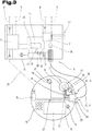
- the lighting control device 25 is structurally arranged in a machine-side coupling counterpart 19.
- Such an arrangement or embodiment of the control system 1 can be particularly advantageous in the case of cable-based signal connections 22 between the safety switching element 15 of the handheld operating device 10 and a control device 6 or safety controller 7 of the control system 1.
- Such an embodiment is also in the Fig. 3 shown, whereby in the Fig. 3
- a hand-held control unit, as well as further components of the control system 1, excerpts and in comparison to FIG Fig. 1 are shown enlarged.
- the same reference numerals or component designations are used for the same parts as in Fig. 1 and Fig. 2 used. To avoid unnecessary repetition, please refer to the detailed description of the Fig. 1 and Fig. 2 pointed out or referred to.
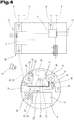
- the at least one lighting control device 25 is structurally arranged in the hand-held operating device 10.
- Such an embodiment is in the Fig. 4 illustrated, also in the Fig. 4 Again, the same reference numerals or component designations are used for the same parts as in FIGS FIGS. 1 to 3 be used.
- the one in the Fig. 4 The embodiment shown can be particularly useful in the case of a purely wireless signal connection 22 between the safety switching element 15 and a control device 6 or safety controller 7 of the control system 1.
- a power supply means 24 for the electrical power supply of the lighting device 17 can of course be arranged or integrated on or in the hand-held control device 10.
- those in the Fig. 3 and the Fig. 4 The illustrated embodiments represent alternative solutions, in particular for the configuration of the signal connection 22. It should be noted at this point, however, that the in the Fig. 3 The embodiment shown in principle also with that in FIG Fig. 4 embodiment shown can be combined.
- control system can therefore also each comprise both a lighting control device 25 in a coupling counterpart 19 and a lighting control device 25 in a handheld control device 10, in which case the control system 1 is used to select one of the lighting control devices 25 for the electrical or electronic adjustment of the visually perceptible ones Luminous intensity of the lighting device 17 can be formed.
- control system 1 is used to select one of the lighting control devices 25 for the electrical or electronic adjustment of the visually perceptible ones Luminous intensity of the lighting device 17 can be formed.
- a corresponding selection is made by an operator.
- At least one manually adjustable input setting means 26 can be functionally assigned to the at least one lighting control device 25.
- the lighting control device 25 can be designed for the electrically and / or electronically controlled adjustment of the visually perceptible light intensity of the lighting device 17 on the basis of a respective position of the input setting means 26.
- a manually adjustable input setting means 26 can be formed, for example, by a rotary or slide control functionally connected to the lighting control device 25.
- input setting means 26 in the form of plus and minus buttons or other design variants are also conceivable.
- such an input setting means 26 can be arranged on the hand-held control device 10 itself, wherein in the case of a lighting control device 25 arranged in the hand-held control device, the input setting means 26 can be functionally linked directly to the lighting control device 25. This case is exemplified in the Fig. 4 illustrated.
- an input setting means 26 placed on the hand-held operating device 10 can also, for example, be provided by a be functionally connected to the corresponding lighting control device 25 via the cable 21, as exemplified in FIG Fig. 3 is shown.
- corresponding input setting means 26 can of course also be placed in the area of a coupling counterpart 19 at a position that is as easily accessible as possible.
- the at least one lighting control device 25 for the electrically and / or electronically controlled adaptation of the visually perceptible light intensity of the lighting device 17 within a limited range between a control-technically predeterminable one or adaptable, minimum limit intensity and a control-technically predeterminable or adaptable, maximum limit intensity is formed.
- the minimum and maximum limit intensity can each be specified or stored electronically readable by the lighting control device 25, for example in a memory unit of a control device 6, 7 of the control system 1 or a memory unit of the lighting control device 25 itself.
- the lighting control device 25 is designed for the control-technical specification or adaptation of the corresponding limit intensities for the light intensity. This can take place, for example, on the basis of sensors, etc. connected to the lighting control device 25, as will be explained in more detail below.
- the control system 1 can comprise at least one detection means 27 for monitoring user activities.
- a detection means 27 is preferably arranged on or in the hand-held control device 10 itself, and can, for example, include motion sensors, position and / or acceleration sensors or a gyroscope, optical sensors, or also time measuring devices for monitoring a timeout for a non-existence of user activities, in particular of user input.
- Correspondingly configured detection means 27 can be designed to signal a detected presence or a detected non-presence of user activities to the at least one lighting control device 25.
- the at least one lighting control device 25 can, when there is a coupled signal connection 22 between the safety switching element 15 and a control device 6 or a safety controller 7, and when the presence of user activities is signaled, for the electrically and / or electronically controlled adjustment of the visually perceptible light intensity a first, low level be formed. If there is a coupled signal connection 22 and if the detection means 27 signals that there is no user activity, the lighting control device 25 can, on the other hand, be designed for the electrically and / or electronically controlled adjustment of the visually perceptible light intensity to a second level, which is higher than the first level. In the latter case, the adjustment or setting of the higher, second luminous intensity level can, if necessary, also take place after a definable period of time has elapsed or after the signaling of the absence of user activities.
- an embodiment of the control system 1 can be advantageous in which the coupling counterpart (s) 19 of a control system 1 is assigned an identifier, which identifier is data-technical information with regard to a minimum limit intensity and / or an optimal level for the visually perceptible light intensity in the area of the assigned system component 3.
- an identifier can be formed, for example, by a data identifier stored in terms of data in a memory unit of a control device 6 or safety controller 7 or in a memory unit of a lighting control device 25 assigned to the respective coupling counterpart 19.
- the lighting control device can be designed for direct detection of the identifier by reading out such an identifier from the corresponding memory unit using data technology.
- the lighting control device is designed for indirect detection of an identifier 28 via an identifier detection means 29.
- an identifier detection means 29 is formed on the handheld operating device 10, which depending on the type or design of the identifier 28, for example, as a barcode or 2D code reader, or as an RFID scanner and the like can be formed.
- an identifier 28 that can correspondingly be detected with the identifier detection means for example a bar code or 2D code, or an RFID transponder, can be attached to the end in the region of the plug connection 23 of the cable 21.
- the identifier 28 can then be read out by means of the identifier detection means 29 and transmitted, for example, via the cable 21 to the lighting control device 25 arranged in the counterpart coupling point 19.
- the lighting control device 25 can be designed for the electrically or electronically controlled adjustment of the visually perceptible light intensity on the basis of the data-related information of the identifier 28.
- the identifier 28 can also have data-technical information about the already described minimum limit intensity and / or the maximum limit intensity for the corresponding system component or coupling counterpart 19, or provide it to the lighting control device 25.
- the at least one lighting control device 25 can comprise a first switching means 30, and the lighting control device 25 can be designed to activate or deactivate the lighting device 17 by switching the first switching means 30 to an electrically conductive or a non-conductive switching state.
- a lighting control device 25 arranged in the coupling counterpart 19 is designed to open or close an electrical power supply 31 routed via the cable 21 via the first switching means 30.
- a lighting control device 25 arranged in a hand-held control device 10 can of course also be designed for opening or closing an internal power supply 31 for the lighting device 17 of the hand-held control device 10 via the first switching means 30.
- the at least one lighting control device 25 is designed to electronically adjust the visually perceptible light intensity of the lighting device 17 by applying a pulse-width-modulated control signal to the first switching means 30.
- This design variant of the lighting control device 25 allows a particularly energy-efficient, electronically controlled adaptation of the visually perceptible light intensity for lighting devices 17 suitable for this, which can have lighting means formed by light-emitting diodes or LEDs, for example.
- Such a pulse-width-modulated control signal is characterized by periodically successive pulse intervals and pause intervals.
- the lighting control device 25 switches the electrical power supply 31 conductive or closed via the first switching means 30, so that the lighting device 17 is supplied with power during a pulse interval and lights up accordingly.
- the lighting control device 25 switches the power supply 31 non-conductive or open via the first switching means 30, so that the lighting device 17 is not supplied with power during a pause interval and, accordingly, does not light up.
- the pulse-width-modulated control signal is fed into the respective electrical power supply 31 or the respective lighting device 17 via the first switching means 30, see FIG Fig. 3 or. Fig. 4 , coupled.
- the human eye perceives only the average emitted light intensity of the lighting device 17 as a visually perceptible or visually perceived light intensity.
- the human eye also does not perceive any flickering of the lighting device 17.
- the at least one lighting control device 25 for activating or deactivating the lighting device 17 comprises a second, switchable switching means 32, which second switching means 32 is electrically connected in series with the first switching means 30 is.
- the lighting control device 25 can be designed to switch both switching means 30, 32 into a non-conductive state when the signal connection 22 between the safety switching element 15 and the control device 6 or safety controller 7 is released.
- the lighting control device 25 can in principle also be designed to act on the second switching means 32 with a pulse-width-modulated control signal.
- the at least one lighting control device 25 is assigned at least one checking means 33 for checking the line state or switching state of the switching means (s) 30, 32, and the lighting control device 25 for checking if the lighting device 17 is in a deactivated state the proper non-conductive state of the switching means 30, 32 is formed by means of the at least one checking means 33.
- the checking means 33 can be formed here, for example, by a current measuring means integrated into the electrical power supply 31, by means of which it can be checked whether a lighting device 17 is being supplied with current or not.
- checking means 33 can also be used for this purpose, for example checking means 33 which directly detect a respective switching state of the switching means (s) 30, 32.
- checking means 33 which directly detect a respective switching state of the switching means (s) 30, 32.
- the checking means 33 can therefore also basically be formed by a light-sensitive sensor device. The use of such light-sensitive sensor devices or sensor means for the control system 1 is explained in more detail below.
- the at least one lighting control device 25 is designed to execute a test cycle, which test cycle alternately includes switching one of the switching means 30, 32 to a non-conductive state and the simultaneous switching of the or the other switching means 30, 32 in a conductive state. That way you can the lighting control device 25 via the checking means 33 cyclically check each individual switching means 30, 32 for its functionality, or the lighting control device 25 can check whether each of the switching means 30, 32 can be switched to a proper, non-conductive state by executing a corresponding test cycle.
- the at least one lighting control device 25 is assigned a signal connection status checking means 34 for signaling purposes, which signal connection status checking means 34 is designed to continuously check the coupling status of the signal connection 22, and that the lighting control device 25 in the event of a coupled status of the signal connection 22 for activating the lighting device 17 is formed, and in the case of a released state of the signal connection 22 is formed to deactivate the lighting device 17.
- signal connection status checking means 34 can be designed, for example, for the detection of a proper electrical current flow or test current via the signal connection 22, for example a signal connection 22 routed via the cable 21, as exemplified with the aid of FIG Fig. 3 illustrated embodiment is illustrated.
- a signal connection status checking means 34 is also conceivable, which is used to check correct signal transmission via a cable-connected signal connection 22, or as in FIG Fig. 4 is shown, is designed to check proper signal transmission via a wireless signal connection 22.
- wired signal connections 22 it is in principle also possible to establish an established or disconnected state of a wired signal connection 22 by detecting a connected or disconnected or disconnected or decoupled plug connection 23, as is also greatly simplified in FIG Fig. 3 is shown.
- a signal connection status checking means 34 can be formed here by a coupling status checking means 35, for example a magnetic or inductive sensor, or an optical sensor for detecting whether the plug connection 23 is established or disconnected, as shown in FIG Fig. 3 is shown.
- the at least one lighting control device 25 with at least a first, luminous intensity-sensitive sensor means 36 can be connected in terms of data signal technology.
- the illustrated first sensor means 36 can be arranged structurally in the vicinity of the safety switching element 15, and can be provided for detecting the ambient brightness in the vicinity of the safety switching element 15.
- a sensor means for detecting the ambient brightness can also be arranged inside the safety switching element or its jacket.
- the first sensor means 36 can be arranged on the hand-held control device 10 in such a way that a light detection direction for the first sensor means 36 is arranged pointing away from the safety switching element 15, as indicated by the arrows 37 in FIG Fig. 3 and the Fig. 4 is indicated.
- the at least one lighting control device 25 can be designed for automatic, electrical or electronic adaptation of the visually perceptible light intensity of the lighting device 17 on the basis of the detected ambient brightness.
- the lighting control device 25 can likewise be designed for the automatic, dynamic specification or adaptation of a minimum limit intensity for the lighting device 17 on the basis of the detected ambient brightness.
- the lighting control device 25 is designed, in the event of a detected increase in ambient brightness, to increase the visually perceptible light intensity of the lighting device 17 and / or to increase the default or a default value for the minimum limit intensity.
- the lighting control device 25, in the case of a detected decrease in ambient brightness via the first sensor means 36, can be designed to reduce the visually perceptible light intensity of the lighting device 17 and / or to reduce the default or a default value for the minimum limit intensity.
- the surroundings of a workstation or a system component can be illuminated or illuminated by any type of light source, although a plurality of light sources can of course also be present.
- Ambient illumination sources are also used which, due to their mode of operation, are subject to periodic fluctuations in brightness, especially when fed with AC voltage. Examples are LED lighting, mercury vapor lamps or neon tubes.
- arithmetic smoothing or filtering or arithmetic averaging takes place over a certain observation period, for example in the range of 200 ms, or over several successive measuring points. In this way, such ambient brightness fluctuations can be calculated. In this way, for example, it is possible to prevent the illuminated safety switching element from flickering as a result of the ambient brightness-dependent adaptation of the visually perceptible light intensity of the lighting device.
- a sampling frequency with which the ambient brightness is detected is significantly higher than twice the network frequency. Under no circumstances should the ambient brightness be recorded with a sampling rate that corresponds to twice the network frequency or a frequency divided as a whole number of twice the network frequency, since this could result in beat effects when the ambient brightness is recorded.
- changes in the intensity of the lighting device are always carried out slowly in terms of control technology, with a ramp-like transition in the range of a few seconds.
- This makes it possible to prevent any detected, low-frequency periodic changes in brightness in the ambient brightness, which can be caused, for example, by flashing signal lights in the vicinity, from the controlled adaptation of the light intensity to a safety switching element that can be perceived as flashing accordingly.
- uncertainties or possible confusion among perceiving persons with regard to the meaning of such an alleged light signal can be avoided.
- the first sensor means 36 can, however, also be designed or used to detect coded light signals. Like in the Fig. 4 is illustrated schematically, the control system 1 can for this purpose at least one locally assigned to a system component Include light source 44, which light source 44 is designed to emit a coded light signal.
- the first light intensity-sensitive sensor means 36 can be designed to detect and provide the encoded light signal of the light source 44 with respect to the lighting control device 25.
- the lighting control device 25 is designed to provide information about the detection of a coded light signal to a control device 6 and / or a safety controller 7, and that the respective control device 6 and / or safety controller 7 for enabling at least of observation-relevant control commands is only formed in the case of a provision of information about the detection of a coded light signal by the lighting control device 25.
- the environment of a certain machine or system component can be illuminated with a light signal with a system-specific coding.
- certain operating commands in particular control commands relevant to observation, can only be executed as long as the operator is at least within sight of the respective system component and can visually detect and monitor the effect of his operator actions.
- the at least one lighting control device 25 can additionally be line-connected to a second, luminous intensity-sensitive sensor means 38 by means of data signals, which second sensor means 38 is provided for detecting an actual value of the luminous intensity of the lighting device 17.
- the second sensor means 38 can in turn be structurally arranged in the vicinity of the safety switching element 15 on the hand-held control device 10 such that a light detection direction for the second sensor means 38 is arranged pointing to the safety switching element 15, as indicated by the arrows 39 in FIG Fig. 3 and the Fig. 4 is indicated.
- an arrangement of such a second sensor means within the safety switching element or its jacket is again possible.
- the second sensor means 38 can continuously provide an actual value of the light intensity emitted by the lighting device 17 for the lighting control device 25.
- the at least one lighting control device 25 can be designed to compare the detected actual value of the light intensity of the lighting device 17 with an internally established and / or control-generated setpoint value for the light intensity.
- a setpoint value generated by control technology can be generated, for example, on the basis of or as a function of an ambient brightness that is detected or captured by means of the first, light-sensitive sensor means 36.
- the lighting control device 25 can be designed to provide a setpoint error signal to a control device 6 and / or a safety controller 7 of the control system 1, for example on the basis of the comparison when a defined limit value for a permissible deviation of the actual value from the setpoint is exceeded.
- the lighting control device 25 can of course be used to provide the setpoint error signal both when the setpoint value is undershot and when it is exceeded. In principle, different, permissible deviations for falling below or exceeding the target value can also be defined in this context.
- the at least one lighting control device 25 can basically be designed to compare the detected actual value of the luminous intensity of the lighting device 17 with an internally defined and / or a control-generated setpoint for the luminous intensity.
- the lighting control device 25 can be designed for electrical and / or electronic readjustment of the visually perceptible light intensity of the lighting device 17. With this embodiment, for example, age-related deviations in the light intensity of the lighting device 17 can be corrected automatically or in terms of control technology by means of the lighting control device 25.
- the at least one lighting control device 25 can be designed to adapt the visually perceptible light intensity by applying a pulse-width-modulated control signal to the lighting device 17.
- the second sensor means 38 is designed to detect a time profile of the pulse-width-modulated light emitted by the lighting device 17.
- a means for checking the proper functioning of the lighting device 17 can be provided.
- the lighting control device 25 can be designed to compare a sensor signal of the second sensor means 38 detected during a pulse time interval of the pulse-width-modulated control signal with a sensor signal of the second sensor means 38 detected during a pause time interval of the pulse-width-modulated control signal.
- the lighting control device 25 can provide a pulse-pause error signal in the event of a negative check result or a negative result of the comparison, for example in the event of a discrepancy between the time profile of the pulse-width-modulated control signals and the time profile of the pulse-width-modulated light emitted by the lighting device be designed with respect to a control device 6 and / or a safety controller 7 of the control system 1.
- the at least one lighting control device 25 can also be designed to compare the sensor data provided by the first sensor means 36 and / or the second sensor means 38 with reference data that can be stored or previously stored in the control system 1.
- reference data can be stored, for example, in a memory unit of a control device 6 or a safety controller 7 of the control system 1, and can be electronically read out by the at least one lighting control device 25 when a signal connection 22 is established between the safety switching element 15 and the control device 6 or safety controller 7.
- Such reference data can, for example, also be formed by measurement data from the first and / or second sensor means 36, 38, which are provided for the lighting control device 25 during use of the hand-held control device 10 and are stored in a memory unit by the lighting control device 25. If a permissible deviation of the sensor data from the reference data is exceeded, the lighting control device 25 can be designed to provide a deviation error signal for a control device 6 and / or a safety controller 7 of the control system 1.
- the at least one lighting control device 25 can also comprise a current measuring means 40 for determining the electrical current flow picked up by the lighting device 17, as shown in FIG Fig. 3 and the Fig. 4 is illustrated.
- a current measuring means 40 can be formed, for example, by a measuring transducer which provides a measured value for the lighting control device 25 in terms of signals or data.
- the lighting control device 25 can subsequently be designed to compare the recorded current flow measurement data with reference data stored in a memory unit of the control system 1. If a predetermined deviation of the specific current flow data from the stored reference data is exceeded, the lighting control device 25 can then be designed to provide a current flow error signal to a control device 6 and / or a safety controller 7 of the control system 1.
- the corresponding control device 6 or the corresponding safety controller 7 can immediately transfer the system 2 or the affected system component 3 be designed in a safe state.
- a loss of safety in the system for example due to defects in the lighting device 17 with the increased risk of a person making a mistake about the effectiveness of the safety switching element in a possible emergency, can be prevented until, for example, a necessary maintenance or repair measure has been carried out.
- control device 6 and / or the safety controller 7 are designed for the signaling coupling of an error signal provided by the lighting control device 25 in a signal-equivalent manner to a manually operated safety switching element 15 in a safety circuit 41 for the system 2 or the system component 3 is how this is greatly simplified and also schematically in the Fig. 3 and the Fig. 4 is shown.
- the corresponding control device 6 or the corresponding safety controller 7 can be used when an error signal is provided by the lighting control device 25, however, can also be designed, for example, to block safety-relevant control commands, in particular by deactivating an approval signal from an approval button integrated in the hand-held control device, and / or, for example, to display the error signal or signals.
- FIG. 5 a further and possibly independent embodiment of the control system 1 is shown, again with the same reference numerals or component designations as in the preceding for the same parts FIGS. 1 to 4 be used.
- the control system 1 again with the same reference numerals or component designations as in the preceding for the same parts FIGS. 1 to 4 be used.
- the one in the Fig. 5 The embodiment variant shown can be advantageous when the at least one lighting control device 25 is configured to apply a pulse-width-modulated control signal to the lighting device 17.
- the first sensor means 36 and the second sensor means 38 have a common intensity detection element 42, and that the at least one lighting control device 25 for periodically interrogating the intensity detection element 42 during pulse time intervals and pause time intervals of a pulse-width-modulated control signal for the lighting device 17 is trained.
- the first sensor means 36 and the second sensor means 38 can be structurally essentially formed by a sensor means or a sensor device, which is arranged in a close range with its light detection direction - indicated by arrow 43 - aligned in the direction of the safety switching element 15.
- the distinction between the first sensor means 36 provided for detecting the ambient brightness and the second sensor means 38 provided for detecting an actual value of the luminous intensity of the lighting device is in this case given or by the specific temporally successive interrogation of the common intensity detection element 42 by the lighting control device 25 .
- the lighting control device 25 can make a corresponding, sequential query that is offset in time of the common intensity detection element 42 may be formed.
- the first and second sensor means can therefore also be referred to or understood as virtual first sensor means 36 and virtual second sensor means 38 in this case.
- the at least one lighting control device 25 can be designed to determine the ambient brightness from the sensor data queried during pause time intervals, since during the pause time intervals of the pulse-width-modulated control signal the lighting device 17 is not supplied with energy or electrical current and therefore does not light up.
- FIGS. 2 to 5 illustrated embodiments a further, possibly independent embodiment may also be useful, which in the Fig. 6 is shown. It will be in the Fig. 6 again for the same parts the same reference numerals or component designations as in the preceding Fig. 1 to Fig. 5 used. In order to avoid unnecessary repetition, please refer to the detailed description in the preceding section Figs. 1 to 5 pointed out or referred to.
- the first sensor means 36 and the second sensor means 38 or the common intensity detection element 42 can be structurally arranged within the jacket 16 of the safety switching element 15. In particular, this represents a structurally particularly efficient and space-saving embodiment of the hand-held operating device 10.
- the light intensity of the lighting device 17 and also the ambient brightness can in principle be detected either directly by sensor means 36, 38 arranged inside the safety switching element 15 or its jacket 16, or by sensor means or sensor devices arranged outside after passing through the semitransparent jacket 16 of the safety switching element 15 are recorded.
- the respective detected light intensity of the lighting device 17 can be determined by appropriate, computational adaptation or computational Conversion of the corresponding recorded or measured light intensities into arithmetically well usable, in particular digital values are scaled or arithmetically adapted.
- computational calibration methods can optionally also be used for compensation.
- a respective ambient brightness can of course also be detected in principle by a sensor means 36 arranged within the semitransparent casing 16 of the safety switching element 15.
- a sensor means 36 arranged within the semitransparent casing 16 of the safety switching element 15.
- the brightness measured through the jacket by means of a sensor means 36 or an intensity detection element 42 which may differ from the actual ambient brightness due to absorption and / or light scattering effects and the like, can be correspondingly adjusted or corrected by calculation, for example again by using computational calibration methods or the like.
- the lighting device 17 can have a plurality of differently colored lighting means 18.
- the at least one lighting control device 25 can be designed for separate, electrically and / or electronically controlled adaptation of the individual lighting means 18, as is also the case in FIG Fig. 6 is illustrated schematically.
- the at least one lighting control device 25, in the case of an actuated safety switching element 15, is designed for electrically or electronically controlled adaptation of the lighting device 17 or the individual lighting means 18 by means of a display signal, in particular by a visually perceptible flashing signal.
- a display signal in particular by a visually perceptible flashing signal.
Landscapes
- Engineering & Computer Science (AREA)
- Physics & Mathematics (AREA)
- Architecture (AREA)
- General Physics & Mathematics (AREA)
- General Engineering & Computer Science (AREA)
- Automation & Control Theory (AREA)
- Civil Engineering (AREA)
- Structural Engineering (AREA)
- Electromagnetism (AREA)
- Mechanical Engineering (AREA)
- Circuit Arrangement For Electric Light Sources In General (AREA)
- Fencing (AREA)
Claims (17)
- Système de commande (1) pour des installations contrôlées électriquement (2), comprenant au moins un dispositif de commande (6) pour la surveillance et/ou le contrôle de l'installation (2) et de composants de l'installation (3),
au moins un appareil de commande manuel portatif mobile (10) comprenant des moyens de sortie (11) pour l'affichage d'informations et des moyens d'entrée (13) pour l'entrée de commandes par un opérateur (12), dans lequel l'appareil de commande manuel (10) comprend au moins un élément de commutation de sécurité (15) actionnable manuellement, un dispositif d'éclairage (17) avec au moins un moyen d'éclairage (18) correspondant à cet élément de commutation de sécurité (15),
et une liaison de signaux (22), pouvant être couplée et découplée selon les besoins, entre l'élément de commutation de sécurité (15) de l'appareil de commande manuel (10) et l'au moins un dispositif de commande (6) ou une commande de sécurité (7) séparée, dans lequel le système de commande (1) est conçu pour faire passer, lors de l'existence d'une liaison de signaux couplée (22) et lors de l'actionnement manuel de l'élément de commutation de sécurité (15), l'installation (2) ou un des composants de l'installation (3) dans un état sécurisé,
et dans lequel le système de commande (1) est conçu, lors de l'existence d'une liaison de signaux couplée (22), pour l'activation du dispositif d'éclairage (17) et, lors de l'existence d'une liaison de signaux découplée (22), pour la désactivation du dispositif d'éclairage (17),
caractérisé en ce que
il comprend au moins un dispositif de commande d'éclairage (25) conçu pour l'adaptation contrôlée électriquement et/ou électroniquement d'une intensité lumineuse perceptible visuellement du dispositif d'éclairage (17) à l'intérieur d'une plage limitée entre une intensité limite minimale pouvant être prédéterminée par la commande et une intensité limite maximale pouvant être prédéterminée par la commande, lors de l'existence d'une liaison de signaux couplée (22) entre l'élément de commutation de sécurité (15) de l'appareil de commande manuel (10) et l'au moins un dispositif de commande (6) ou la commande de sécurité (7). - Système de commande selon la revendication 1, caractérisé en ce que, à l'au moins un dispositif de commande d'éclairage (25) correspond fonctionnellement au moins un moyen de réglage d'entrée réglable manuellement (26), dans lequel le dispositif de commande d'éclairage (25) est conçu, lors de l'existence d'une liaison de signaux couplée (22) et lors d'un réglage du moyen de réglage d'entrée (26) par un opérateur (12), pour l'adaptation contrôlée électriquement et/ou électroniquement de l'intensité lumineuse perceptible visuellement du dispositif d'éclairage (17) sur la base d'une position respective du moyen de réglage d'entrée (26).
- Système de commande selon l'une ou plusieurs des revendications précédentes, caractérisé en ce qu'au moins un moyen de détection (27) est prévu pour la surveillance d'activités d'utilisateurs sur un appareil de commande manuel (10), ce moyen de détection (27) étant conçu pour la signalisation d'une existence détectée ou d'une non-existence détectée d'activités d'utilisateurs par rapport à l'au moins un dispositif de commande d'éclairage (25).
- Système de commande selon la revendication 3, caractérisé en ce que l'au moins un dispositif de commande d'éclairage (25) est conçu, lors de l'existence d'une liaison de signaux couplée (22) et lors d'une signalisation d'une existence d'activités d'utilisateurs, pour l'adaptation contrôlée électriquement et/ou électroniquement de l'intensité lumineuse perceptible visuellement à un premier niveau plus bas et, lors de l'existence d'une liaison de signaux couplée (22) et lors d'une signalisation d'une non-existence d'activités d'utilisateurs, pour l'adaptation contrôlée électriquement et/ou électroniquement de l'intensité lumineuse perceptible visuellement à un deuxième niveau plus élevé que le premier niveau.
- Système de commande selon l'une ou plusieurs des revendications précédentes, caractérisé en ce qu'il comprend au moins un poste distant de couplage côté machine (19), qui correspond à un composant d'installation proche contrôlable électriquement (3), dans lequel l'au moins un poste distant de couplage (19) est conçu au moins pour l'établissement et l'annulation de la liaison de signaux (22) entre l'au moins un élément de commutation de sécurité (15) de l'appareil de commande manuel (10) et un dispositif de commande (6) de l'installation (2) et/ou du composant de l'installation (3).
- Système de commande selon la revendication 5, caractérisé en ce que, à l'au moins un poste distance de couplage (19), correspond un identifiant (28), cet identifiant (28) comprenant des informations techniques de données concernant une intensité limite minimale et/ou un niveau optimal pour l'intensité lumineuse perceptible visuellement au niveau du composant d'installation (3) correspondant, et le dispositif de commande d'éclairage (25) est conçu pour la détection directe de l'identifiant ou pour la détection indirecte de l'identifiant (28) via un moyen de détection d'identifiant (29), et pour l'adaptation contrôlée électriquement et/ou électroniquement de l'intensité lumineuse perceptible visuellement sur la base des informations techniques de données de l'identifiant (28).
- Système de commande selon l'une ou plusieurs des revendications précédentes, caractérisé en ce que l'au moins un dispositif de commande d'éclairage (25) comprend au moins un premier moyen de commutation (30) et le dispositif de commande d'éclairage (25) est conçu pour l'activation respectivement la désactivation du dispositif d'éclairage (17) par la commutation du premier moyen de commutation (30) vers un état de commutation électro-conducteur respectivement non électro-conducteur.
- Système de commande selon la revendication 7, caractérisé en ce que l'au moins un dispositif de commande d'éclairage (25) est conçu pour l'adaptation contrôlée électriquement et/ou électroniquement de l'intensité lumineuse perceptible visuellement du dispositif d'éclairage (17) par l'alimentation du premier moyen de commutation (30) avec un signal de commande modulé par largeurs d'impulsions.
- Système de commande selon l'une ou plusieurs des revendications 5 à 8, caractérisé en ce que l'au moins un dispositif de commande d'éclairage (25) est intégré dans le poste distant de couplage côté machine (19).
- Système de commande selon l'une ou plusieurs des revendications 1 à 8, caractérisé en ce que l'au moins un dispositif de commande d'éclairage (25) est intégré dans l'appareil de commande manuel (10).
- Système de commande selon l'une ou plusieurs des revendications précédentes, caractérisé en ce que l'au moins un dispositif de commande d'éclairage (25) est relié par des signaux de données avec au moins un premier moyen de capteur sensible à l'intensité lumineuse (36), ce premier moyen de capteur (36) étant intégré à proximité de l'élément de commutation de sécurité (15) ou disposé à l'intérieur de l'élément de commutation de sécurité (15) et ce premier moyen de capteur (36) étant conçu pour la mesure de la luminosité ambiante à proximité de l'élément de commutation de sécurité (15).
- Système de commande selon la revendication 11, caractérisé en ce que l'au moins un dispositif de commande d'éclairage (25) est conçu pour l'adaptation automatique, contrôlée électriquement et/ou électroniquement de l'intensité lumineuse perceptible visuellement du dispositif d'éclairage (17) sur la base de la luminosité ambiante mesurée et/ou pour la détermination automatique dynamique d'une intensité limite minimale pour le dispositif d'éclairage (17) sur la base de la luminosité ambiante mesurée.
- Système de commande selon l'une des revendications 11 ou 12, caractérisé en ce que l'au moins un dispositif de commande d'éclairage (25) est relié par des signaux de données avec un deuxième moyen de capteur sensible à l'intensité lumineuse (38), ce deuxième moyen de capteur (38) étant intégré à proximité de l'élément de commutation de sécurité (15) ou disposé à l'intérieur de l'élément de commutation de sécurité (15) et pour la mesure d'une valeur réelle de l'intensité lumineuse du dispositif d'éclairage (17).
- Système de commande selon la revendication 13, caractérisé en ce que l'au moins un dispositif de commande d'éclairage (25) est conçu pour la comparaison de la valeur réelle mesurée de l'intensité lumineuse du dispositif d'éclairage (17) avec une valeur de consigne pour l'intensité lumineuse, déterminée en interne et/ou générée par la commande et en ce que le dispositif de commande d'éclairage (25) est conçu pour la régulation électrique et/ou électronique de l'intensité lumineuse perceptible visuellement du dispositif d'éclairage (17) sur la base de la comparaison.
- Système de commande selon l'une des revendications 8 à 14, caractérisé en ce que le premier moyen de capteur (36) et le deuxième moyen de capteur (38) comprennent un élément de mesure d'intensité commun (42) et en ce que l'au moins un dispositif de commande d'éclairage (25) est conçu pour la lecture périodique de l'élément de mesure d'intensité (42) pendant des intervalles d'impulsions et des intervalles de pauses d'un signal de commande modulé par largeurs d'impulsions pour le dispositif d'éclairage (17).
- Système de commande selon la revendication 15, caractérisé en ce que l'au moins un dispositif de commande d'éclairage (25) est conçu pour la détermination de la luminosité ambiante à partir des données de capteurs lues pendant les intervalles de pauses.
- Système de commande selon l'une ou plusieurs des revendications précédentes, caractérisé en ce que le dispositif d'éclairage (17) comprend plusieurs moyens d'éclairage (18) de différentes couleurs, et en ce que l'au moins un dispositif de commande d'éclairage (25) est conçu pour l'adaptation séparée, contrôlée électriquement et/ou électroniquement des différents moyens d'éclairage (18).
Priority Applications (1)
| Application Number | Priority Date | Filing Date | Title |
|---|---|---|---|
| EP21175708.3A EP3889981B1 (fr) | 2016-02-18 | 2017-02-10 | Système de commande d'installations commandées électriquement |
Applications Claiming Priority (2)
| Application Number | Priority Date | Filing Date | Title |
|---|---|---|---|
| AT501082016 | 2016-02-18 | ||
| PCT/AT2017/060024 WO2017139817A1 (fr) | 2016-02-18 | 2017-02-10 | Système de commande d'installations commandées électriquement |
Related Child Applications (2)
| Application Number | Title | Priority Date | Filing Date |
|---|---|---|---|
| EP21175708.3A Division EP3889981B1 (fr) | 2016-02-18 | 2017-02-10 | Système de commande d'installations commandées électriquement |
| EP21175708.3A Division-Into EP3889981B1 (fr) | 2016-02-18 | 2017-02-10 | Système de commande d'installations commandées électriquement |
Publications (2)
| Publication Number | Publication Date |
|---|---|
| EP3417465A1 EP3417465A1 (fr) | 2018-12-26 |
| EP3417465B1 true EP3417465B1 (fr) | 2021-06-30 |
Family
ID=58401288
Family Applications (2)
| Application Number | Title | Priority Date | Filing Date |
|---|---|---|---|
| EP17712915.2A Active EP3417465B1 (fr) | 2016-02-18 | 2017-02-10 | Système de commande d'installations commandées électriquement |
| EP21175708.3A Active EP3889981B1 (fr) | 2016-02-18 | 2017-02-10 | Système de commande d'installations commandées électriquement |
Family Applications After (1)
| Application Number | Title | Priority Date | Filing Date |
|---|---|---|---|
| EP21175708.3A Active EP3889981B1 (fr) | 2016-02-18 | 2017-02-10 | Système de commande d'installations commandées électriquement |
Country Status (5)
| Country | Link |
|---|---|
| US (1) | US10945328B2 (fr) |
| EP (2) | EP3417465B1 (fr) |
| CN (1) | CN109074973B (fr) |
| AT (1) | AT518814B1 (fr) |
| WO (1) | WO2017139817A1 (fr) |
Families Citing this family (7)
| Publication number | Priority date | Publication date | Assignee | Title |
|---|---|---|---|---|
| US10360790B2 (en) * | 2016-04-22 | 2019-07-23 | Banner Engineering Corp. | Safety touch button system having an intercommunications link |
| US11879871B2 (en) * | 2018-11-30 | 2024-01-23 | Illinois Tool Works Inc. | Safety systems requiring intentional function activation and material testing systems including safety systems requiring intentional function activation |
| US11726018B2 (en) * | 2018-11-30 | 2023-08-15 | Illinois Tool Works Inc. | Safety system interfaces and material testing systems including safety system interfaces |
| DE102019102124A1 (de) * | 2019-01-29 | 2020-07-30 | Bayerische Motoren Werke Aktiengesellschaft | Beleuchtungsvorrichtung für ein Kraftfahrzeug |
| DE102021114870A1 (de) | 2021-06-09 | 2022-12-15 | ACD Antriebstechnik GmbH | Optisches Überwachungssystem für ein optisches Anzeigeelement |
| DE102021126255A1 (de) * | 2021-10-11 | 2023-04-13 | Kuka Deutschland Gmbh | Elektrisches Not-Halt-Gerät und Verfahren |
| LU503513B1 (de) * | 2023-02-17 | 2024-08-19 | ACD Antriebstechnik GmbH | Bedieneinheit und Verfahren zum Bedienen einer Anlage mit einer Bedieneinheit |
Family Cites Families (18)
| Publication number | Priority date | Publication date | Assignee | Title |
|---|---|---|---|---|
| DE9013448U1 (de) | 1990-09-24 | 1992-01-30 | Gebr. Hein Gmbh & Co Kg, 6900 Heidelberg | Schalter |
| US5601278A (en) * | 1995-01-17 | 1997-02-11 | Graber; Loren | Picket fence |
| DE29717703U1 (de) * | 1997-10-04 | 1997-11-13 | Zabel, Walter, 97816 Lohr | Zaunsystem |
| DE19818357A1 (de) * | 1998-04-24 | 1999-10-28 | Matthias Kreusel | Befestigungssatz für einen Querriegel eines Zaunes oder dergleichen |
| DE19919012A1 (de) | 1999-04-27 | 2000-11-02 | Scheer Michael | Verfahren zur Überwachung von Not-Aus-Befehlseinrichtungen |
| FR2802731B1 (fr) * | 1999-12-16 | 2002-01-25 | Schneider Electric Ind Sa | Dispositif autonome de commande a distance, appareil et installation electrique comportant un tel dispositif |
| JP2003067114A (ja) | 2001-08-24 | 2003-03-07 | Matsushita Electric Ind Co Ltd | 照光装置 |
| JP2004319258A (ja) | 2003-04-16 | 2004-11-11 | Idec Izumi Corp | 押しボタンスイッチ及び操作盤 |
| DE10344385A1 (de) * | 2003-09-23 | 2005-05-04 | Peter Wratil | Notaus-Gerät und Verfahren zum Bereitstellen einer Notabschaltungsfunktion |
| JP4548307B2 (ja) * | 2005-10-31 | 2010-09-22 | ソニー株式会社 | 分離型処理装置及びそのソフトウエアの版更新方法 |
| TWI318072B (en) * | 2005-11-03 | 2009-12-01 | Innolux Display Corp | Method of updating luminance of light emitting elements according to ambient light intensity sensed by lmage capturing units of a portable electronic device |
| DE102006029067A1 (de) | 2006-06-24 | 2008-01-03 | Kuka Roboter Gmbh | Notaus-Taster vorzugsweise für tragbares Bediengerät |
| EP1780738A1 (fr) | 2006-07-07 | 2007-05-02 | Siemens Aktiengesellschaft | Commutateur éclairable pour dispositifs de commande mobiles |
| US9349546B2 (en) * | 2013-01-31 | 2016-05-24 | Rockwell Automation Technologies, Inc. | Industrial automation emergency stop with state indictor |
| JP6079469B2 (ja) | 2013-06-21 | 2017-02-15 | トヨタ紡織株式会社 | 照明付タッチスイッチ装置 |
| US9495040B2 (en) * | 2013-11-21 | 2016-11-15 | Ford Global Technologies, Llc | Selectively visible user interface |
| FR3022646B1 (fr) * | 2014-06-20 | 2017-11-10 | Somfy Sas | Procede de fonctionnement d'un dispositif de commande d'une installation domotique d'un batiment et dispositif de commande. |
| DE102015111647A1 (de) | 2014-08-06 | 2016-02-11 | Ford Global Technologies, Llc | Selektiv sichtbare benutzerschnittstelle |
-
2016
- 2016-06-17 AT ATA8005/2017A patent/AT518814B1/de active
-
2017
- 2017-02-10 CN CN201780023984.7A patent/CN109074973B/zh active Active
- 2017-02-10 EP EP17712915.2A patent/EP3417465B1/fr active Active
- 2017-02-10 US US15/999,283 patent/US10945328B2/en active Active
- 2017-02-10 WO PCT/AT2017/060024 patent/WO2017139817A1/fr active Application Filing
- 2017-02-10 EP EP21175708.3A patent/EP3889981B1/fr active Active
Also Published As
| Publication number | Publication date |
|---|---|
| CN109074973A (zh) | 2018-12-21 |
| AT518814B1 (de) | 2018-04-15 |
| WO2017139817A1 (fr) | 2017-08-24 |
| US10945328B2 (en) | 2021-03-09 |
| US20200352007A1 (en) | 2020-11-05 |
| CN109074973B (zh) | 2020-01-17 |
| EP3417465A1 (fr) | 2018-12-26 |
| EP3889981A1 (fr) | 2021-10-06 |
| EP3889981B1 (fr) | 2022-11-02 |
| AT518814A1 (de) | 2018-01-15 |
Similar Documents
| Publication | Publication Date | Title |
|---|---|---|
| EP3417465B1 (fr) | Système de commande d'installations commandées électriquement | |
| EP2780767B1 (fr) | Système comportant un dispositif d'entraînement à moteur électrique pour meubles et un appareil informatique ; procédé destiné à établir une connexion de communication entre le dispositif d'entraînement à moteur électrique pour meubles et l'appareil informatique ; et un tel dispositif d'entraînement pour meubles | |
| EP3013123B1 (fr) | Système d'éclairage et procédé de commande correspondant | |
| AT521872A1 (de) | Verfahren zum Betreiben eines Maschinensteuerungssystems sowie entsprechendes Maschinensteuerungssystem | |
| EP3417348B1 (fr) | Système de commande pour installations à commande électrique | |
| WO2017067918A1 (fr) | Capteur de sécurité pour surveiller la sécurité d'une installation | |
| EP3371663B1 (fr) | Système de commande d'installations à commande électrique | |
| DE10332708B3 (de) | Einrichtung zur berührungslosen Einstellung der Menge und/oder der Temperatur des aus einer Sanitärarmatur ausfließenden Wassers | |
| EP3317738A1 (fr) | Thermostat pour installations de chauffage, climatisation et/ou ventilation | |
| AT518665B1 (de) | Steuerungssystem für elektrisch gesteuerte Anlagen | |
| EP3717974B1 (fr) | Procédé destiné à faire fonctionner un système de commande de machine et système de commande de machine correspondant | |
| WO2018108303A1 (fr) | Dispositifs et procédé de couplage d'un appareil de commande manuelle portable à un manipulateur | |
| LU503513B1 (de) | Bedieneinheit und Verfahren zum Bedienen einer Anlage mit einer Bedieneinheit | |
| EP3188576A1 (fr) | Système d'éclairage, utilisation d'un système d'éclairage et dispositif d'éclairage destiné à être utilisé dans un système d'éclairage | |
| WO2023061804A1 (fr) | Appareil d'arrêt d'urgence électrique et procédé | |
| DE102017124801B4 (de) | Bewegungsmelder sowie Verfahren zum Einrichten der helligkeitsabhängigen Schaltschwelle eines Bewegungsmelders | |
| EP1297390B1 (fr) | Systeme pourvu d'au moins une technique de commande et de plusieurs capteurs a dispositifs de signalisation | |
| DE102011013886A1 (de) | Vorrichtung zum automatisierten Steuern einer technischen Anlage | |
| EP3772869A1 (fr) | Dispositif d'éclairage commandé sans couplage arrière | |
| DE202015104278U1 (de) | Lichtgitter zum Rücksetzen einer Konfiguration |
Legal Events
| Date | Code | Title | Description |
|---|---|---|---|
| STAA | Information on the status of an ep patent application or granted ep patent |
Free format text: STATUS: UNKNOWN |
|
| STAA | Information on the status of an ep patent application or granted ep patent |
Free format text: STATUS: THE INTERNATIONAL PUBLICATION HAS BEEN MADE |
|
| PUAI | Public reference made under article 153(3) epc to a published international application that has entered the european phase |
Free format text: ORIGINAL CODE: 0009012 |
|
| STAA | Information on the status of an ep patent application or granted ep patent |
Free format text: STATUS: REQUEST FOR EXAMINATION WAS MADE |
|
| 17P | Request for examination filed |
Effective date: 20180914 |
|
| AK | Designated contracting states |
Kind code of ref document: A1 Designated state(s): AL AT BE BG CH CY CZ DE DK EE ES FI FR GB GR HR HU IE IS IT LI LT LU LV MC MK MT NL NO PL PT RO RS SE SI SK SM TR |
|
| AX | Request for extension of the european patent |
Extension state: BA ME |
|
| STAA | Information on the status of an ep patent application or granted ep patent |
Free format text: STATUS: REQUEST FOR EXAMINATION WAS MADE |
|
| DAV | Request for validation of the european patent (deleted) | ||
| DAX | Request for extension of the european patent (deleted) | ||
| GRAP | Despatch of communication of intention to grant a patent |
Free format text: ORIGINAL CODE: EPIDOSNIGR1 |
|
| STAA | Information on the status of an ep patent application or granted ep patent |
Free format text: STATUS: GRANT OF PATENT IS INTENDED |
|
| INTG | Intention to grant announced |
Effective date: 20210210 |
|
| GRAS | Grant fee paid |
Free format text: ORIGINAL CODE: EPIDOSNIGR3 |
|
| GRAA | (expected) grant |
Free format text: ORIGINAL CODE: 0009210 |
|
| STAA | Information on the status of an ep patent application or granted ep patent |
Free format text: STATUS: THE PATENT HAS BEEN GRANTED |
|
| AK | Designated contracting states |
Kind code of ref document: B1 Designated state(s): AL AT BE BG CH CY CZ DE DK EE ES FI FR GB GR HR HU IE IS IT LI LT LU LV MC MK MT NL NO PL PT RO RS SE SI SK SM TR |
|
| REG | Reference to a national code |
Ref country code: CH Ref legal event code: EP |
|
| RIN1 | Information on inventor provided before grant (corrected) |
Inventor name: FISCHER, HARALD Inventor name: KREUNDL, ROBERT Inventor name: LEHNER, BERNHARD Inventor name: PREISINGER, GERNOT Inventor name: SCHININGER, MANFRED |
|
| REG | Reference to a national code |
Ref country code: AT Ref legal event code: REF Ref document number: 1407121 Country of ref document: AT Kind code of ref document: T Effective date: 20210715 |
|
| REG | Reference to a national code |
Ref country code: DE Ref legal event code: R096 Ref document number: 502017010785 Country of ref document: DE |
|
| REG | Reference to a national code |
Ref country code: IE Ref legal event code: FG4D Free format text: LANGUAGE OF EP DOCUMENT: GERMAN |
|
| REG | Reference to a national code |
Ref country code: LT Ref legal event code: MG9D |
|
| PG25 | Lapsed in a contracting state [announced via postgrant information from national office to epo] |
Ref country code: HR Free format text: LAPSE BECAUSE OF FAILURE TO SUBMIT A TRANSLATION OF THE DESCRIPTION OR TO PAY THE FEE WITHIN THE PRESCRIBED TIME-LIMIT Effective date: 20210630 Ref country code: BG Free format text: LAPSE BECAUSE OF FAILURE TO SUBMIT A TRANSLATION OF THE DESCRIPTION OR TO PAY THE FEE WITHIN THE PRESCRIBED TIME-LIMIT Effective date: 20210930 Ref country code: FI Free format text: LAPSE BECAUSE OF FAILURE TO SUBMIT A TRANSLATION OF THE DESCRIPTION OR TO PAY THE FEE WITHIN THE PRESCRIBED TIME-LIMIT Effective date: 20210630 |
|
| REG | Reference to a national code |
Ref country code: NL Ref legal event code: MP Effective date: 20210630 |
|
| PG25 | Lapsed in a contracting state [announced via postgrant information from national office to epo] |
Ref country code: LV Free format text: LAPSE BECAUSE OF FAILURE TO SUBMIT A TRANSLATION OF THE DESCRIPTION OR TO PAY THE FEE WITHIN THE PRESCRIBED TIME-LIMIT Effective date: 20210630 Ref country code: GR Free format text: LAPSE BECAUSE OF FAILURE TO SUBMIT A TRANSLATION OF THE DESCRIPTION OR TO PAY THE FEE WITHIN THE PRESCRIBED TIME-LIMIT Effective date: 20211001 Ref country code: NO Free format text: LAPSE BECAUSE OF FAILURE TO SUBMIT A TRANSLATION OF THE DESCRIPTION OR TO PAY THE FEE WITHIN THE PRESCRIBED TIME-LIMIT Effective date: 20210930 Ref country code: RS Free format text: LAPSE BECAUSE OF FAILURE TO SUBMIT A TRANSLATION OF THE DESCRIPTION OR TO PAY THE FEE WITHIN THE PRESCRIBED TIME-LIMIT Effective date: 20210630 Ref country code: SE Free format text: LAPSE BECAUSE OF FAILURE TO SUBMIT A TRANSLATION OF THE DESCRIPTION OR TO PAY THE FEE WITHIN THE PRESCRIBED TIME-LIMIT Effective date: 20210630 |
|
| PG25 | Lapsed in a contracting state [announced via postgrant information from national office to epo] |
Ref country code: SK Free format text: LAPSE BECAUSE OF FAILURE TO SUBMIT A TRANSLATION OF THE DESCRIPTION OR TO PAY THE FEE WITHIN THE PRESCRIBED TIME-LIMIT Effective date: 20210630 Ref country code: SM Free format text: LAPSE BECAUSE OF FAILURE TO SUBMIT A TRANSLATION OF THE DESCRIPTION OR TO PAY THE FEE WITHIN THE PRESCRIBED TIME-LIMIT Effective date: 20210630 Ref country code: PT Free format text: LAPSE BECAUSE OF FAILURE TO SUBMIT A TRANSLATION OF THE DESCRIPTION OR TO PAY THE FEE WITHIN THE PRESCRIBED TIME-LIMIT Effective date: 20211102 Ref country code: RO Free format text: LAPSE BECAUSE OF FAILURE TO SUBMIT A TRANSLATION OF THE DESCRIPTION OR TO PAY THE FEE WITHIN THE PRESCRIBED TIME-LIMIT Effective date: 20210630 Ref country code: NL Free format text: LAPSE BECAUSE OF FAILURE TO SUBMIT A TRANSLATION OF THE DESCRIPTION OR TO PAY THE FEE WITHIN THE PRESCRIBED TIME-LIMIT Effective date: 20210630 Ref country code: ES Free format text: LAPSE BECAUSE OF FAILURE TO SUBMIT A TRANSLATION OF THE DESCRIPTION OR TO PAY THE FEE WITHIN THE PRESCRIBED TIME-LIMIT Effective date: 20210630 Ref country code: EE Free format text: LAPSE BECAUSE OF FAILURE TO SUBMIT A TRANSLATION OF THE DESCRIPTION OR TO PAY THE FEE WITHIN THE PRESCRIBED TIME-LIMIT Effective date: 20210630 Ref country code: CZ Free format text: LAPSE BECAUSE OF FAILURE TO SUBMIT A TRANSLATION OF THE DESCRIPTION OR TO PAY THE FEE WITHIN THE PRESCRIBED TIME-LIMIT Effective date: 20210630 |
|
| PG25 | Lapsed in a contracting state [announced via postgrant information from national office to epo] |
Ref country code: PL Free format text: LAPSE BECAUSE OF FAILURE TO SUBMIT A TRANSLATION OF THE DESCRIPTION OR TO PAY THE FEE WITHIN THE PRESCRIBED TIME-LIMIT Effective date: 20210630 |
|
| REG | Reference to a national code |
Ref country code: DE Ref legal event code: R097 Ref document number: 502017010785 Country of ref document: DE |
|
| PG25 | Lapsed in a contracting state [announced via postgrant information from national office to epo] |
Ref country code: DK Free format text: LAPSE BECAUSE OF FAILURE TO SUBMIT A TRANSLATION OF THE DESCRIPTION OR TO PAY THE FEE WITHIN THE PRESCRIBED TIME-LIMIT Effective date: 20210630 |
|
| PLBE | No opposition filed within time limit |
Free format text: ORIGINAL CODE: 0009261 |
|
| STAA | Information on the status of an ep patent application or granted ep patent |
Free format text: STATUS: NO OPPOSITION FILED WITHIN TIME LIMIT |
|
| REG | Reference to a national code |
Ref country code: DE Ref legal event code: R081 Ref document number: 502017010785 Country of ref document: DE Owner name: KEBA INDUSTRIAL AUTOMATION GMBH, AT Free format text: FORMER OWNER: KEBA AG, LINZ, AT |
|
| PG25 | Lapsed in a contracting state [announced via postgrant information from national office to epo] |
Ref country code: AL Free format text: LAPSE BECAUSE OF FAILURE TO SUBMIT A TRANSLATION OF THE DESCRIPTION OR TO PAY THE FEE WITHIN THE PRESCRIBED TIME-LIMIT Effective date: 20210630 |
|
| 26N | No opposition filed |
Effective date: 20220331 |
|
| PG25 | Lapsed in a contracting state [announced via postgrant information from national office to epo] |
Ref country code: IT Free format text: LAPSE BECAUSE OF FAILURE TO SUBMIT A TRANSLATION OF THE DESCRIPTION OR TO PAY THE FEE WITHIN THE PRESCRIBED TIME-LIMIT Effective date: 20210630 |
|
| PG25 | Lapsed in a contracting state [announced via postgrant information from national office to epo] |
Ref country code: MC Free format text: LAPSE BECAUSE OF FAILURE TO SUBMIT A TRANSLATION OF THE DESCRIPTION OR TO PAY THE FEE WITHIN THE PRESCRIBED TIME-LIMIT Effective date: 20210630 |
|
| REG | Reference to a national code |
Ref country code: CH Ref legal event code: PL |
|
| REG | Reference to a national code |
Ref country code: BE Ref legal event code: MM Effective date: 20220228 |
|
| GBPC | Gb: european patent ceased through non-payment of renewal fee |
Effective date: 20220210 |
|
| PG25 | Lapsed in a contracting state [announced via postgrant information from national office to epo] |
Ref country code: LU Free format text: LAPSE BECAUSE OF NON-PAYMENT OF DUE FEES Effective date: 20220210 |
|
| REG | Reference to a national code |
Ref country code: AT Ref legal event code: PC Ref document number: 1407121 Country of ref document: AT Kind code of ref document: T Owner name: KEBA INDUSTRIAL AUTOMATION GMBH, AT Effective date: 20221018 |
|
| PG25 | Lapsed in a contracting state [announced via postgrant information from national office to epo] |
Ref country code: IE Free format text: LAPSE BECAUSE OF NON-PAYMENT OF DUE FEES Effective date: 20220210 Ref country code: GB Free format text: LAPSE BECAUSE OF NON-PAYMENT OF DUE FEES Effective date: 20220210 Ref country code: CH Free format text: LAPSE BECAUSE OF NON-PAYMENT OF DUE FEES Effective date: 20220228 Ref country code: LI Free format text: LAPSE BECAUSE OF NON-PAYMENT OF DUE FEES Effective date: 20220228 |
|
| PG25 | Lapsed in a contracting state [announced via postgrant information from national office to epo] |
Ref country code: BE Free format text: LAPSE BECAUSE OF NON-PAYMENT OF DUE FEES Effective date: 20220228 |
|
| PG25 | Lapsed in a contracting state [announced via postgrant information from national office to epo] |
Ref country code: LT Free format text: LAPSE BECAUSE OF FAILURE TO SUBMIT A TRANSLATION OF THE DESCRIPTION OR TO PAY THE FEE WITHIN THE PRESCRIBED TIME-LIMIT Effective date: 20210630 |
|
| PG25 | Lapsed in a contracting state [announced via postgrant information from national office to epo] |
Ref country code: HU Free format text: LAPSE BECAUSE OF FAILURE TO SUBMIT A TRANSLATION OF THE DESCRIPTION OR TO PAY THE FEE WITHIN THE PRESCRIBED TIME-LIMIT; INVALID AB INITIO Effective date: 20170210 |
|
| PGFP | Annual fee paid to national office [announced via postgrant information from national office to epo] |
Ref country code: AT Payment date: 20240109 Year of fee payment: 8 |
|
| PG25 | Lapsed in a contracting state [announced via postgrant information from national office to epo] |
Ref country code: MK Free format text: LAPSE BECAUSE OF FAILURE TO SUBMIT A TRANSLATION OF THE DESCRIPTION OR TO PAY THE FEE WITHIN THE PRESCRIBED TIME-LIMIT Effective date: 20210630 Ref country code: CY Free format text: LAPSE BECAUSE OF FAILURE TO SUBMIT A TRANSLATION OF THE DESCRIPTION OR TO PAY THE FEE WITHIN THE PRESCRIBED TIME-LIMIT Effective date: 20210630 |
|
| PGFP | Annual fee paid to national office [announced via postgrant information from national office to epo] |
Ref country code: DE Payment date: 20240108 Year of fee payment: 8 |
|
| PGFP | Annual fee paid to national office [announced via postgrant information from national office to epo] |
Ref country code: FR Payment date: 20240129 Year of fee payment: 8 |
|
| PG25 | Lapsed in a contracting state [announced via postgrant information from national office to epo] |
Ref country code: TR Free format text: LAPSE BECAUSE OF FAILURE TO SUBMIT A TRANSLATION OF THE DESCRIPTION OR TO PAY THE FEE WITHIN THE PRESCRIBED TIME-LIMIT Effective date: 20210630 |