EP3371663B1 - Système de commande d'installations à commande électrique - Google Patents
Système de commande d'installations à commande électrique Download PDFInfo
- Publication number
- EP3371663B1 EP3371663B1 EP16787892.5A EP16787892A EP3371663B1 EP 3371663 B1 EP3371663 B1 EP 3371663B1 EP 16787892 A EP16787892 A EP 16787892A EP 3371663 B1 EP3371663 B1 EP 3371663B1
- Authority
- EP
- European Patent Office
- Prior art keywords
- coupling
- control unit
- manual control
- control system
- designed
- Prior art date
- Legal status (The legal status is an assumption and is not a legal conclusion. Google has not performed a legal analysis and makes no representation as to the accuracy of the status listed.)
- Active
Links
Images

Classifications
-
- G—PHYSICS
- G05—CONTROLLING; REGULATING
- G05B—CONTROL OR REGULATING SYSTEMS IN GENERAL; FUNCTIONAL ELEMENTS OF SUCH SYSTEMS; MONITORING OR TESTING ARRANGEMENTS FOR SUCH SYSTEMS OR ELEMENTS
- G05B19/00—Program-control systems
- G05B19/02—Program-control systems electric
- G05B19/04—Program control other than numerical control, i.e. in sequence controllers or logic controllers
- G05B19/042—Program control other than numerical control, i.e. in sequence controllers or logic controllers using digital processors
- G05B19/0423—Input/output
- G05B19/0425—Safety, monitoring
-
- B—PERFORMING OPERATIONS; TRANSPORTING
- B25—HAND TOOLS; PORTABLE POWER-DRIVEN TOOLS; MANIPULATORS
- B25J—MANIPULATORS; CHAMBERS PROVIDED WITH MANIPULATION DEVICES
- B25J13/00—Controls for manipulators
- B25J13/006—Controls for manipulators by means of a wireless system for controlling one or several manipulators
-
- B—PERFORMING OPERATIONS; TRANSPORTING
- B25—HAND TOOLS; PORTABLE POWER-DRIVEN TOOLS; MANIPULATORS
- B25J—MANIPULATORS; CHAMBERS PROVIDED WITH MANIPULATION DEVICES
- B25J13/00—Controls for manipulators
- B25J13/06—Control stands, e.g. consoles, switchboards
-
- B—PERFORMING OPERATIONS; TRANSPORTING
- B25—HAND TOOLS; PORTABLE POWER-DRIVEN TOOLS; MANIPULATORS
- B25J—MANIPULATORS; CHAMBERS PROVIDED WITH MANIPULATION DEVICES
- B25J13/00—Controls for manipulators
- B25J13/06—Control stands, e.g. consoles, switchboards
- B25J13/065—Control stands, e.g. consoles, switchboards comprising joy-sticks
-
- B—PERFORMING OPERATIONS; TRANSPORTING
- B25—HAND TOOLS; PORTABLE POWER-DRIVEN TOOLS; MANIPULATORS
- B25J—MANIPULATORS; CHAMBERS PROVIDED WITH MANIPULATION DEVICES
- B25J19/00—Accessories fitted to manipulators, e.g. for monitoring, for viewing; Safety devices combined with or specially adapted for use in connection with manipulators
- B25J19/06—Safety devices
-
- G—PHYSICS
- G05—CONTROLLING; REGULATING
- G05B—CONTROL OR REGULATING SYSTEMS IN GENERAL; FUNCTIONAL ELEMENTS OF SUCH SYSTEMS; MONITORING OR TESTING ARRANGEMENTS FOR SUCH SYSTEMS OR ELEMENTS
- G05B19/00—Program-control systems
- G05B19/02—Program-control systems electric
- G05B19/04—Program control other than numerical control, i.e. in sequence controllers or logic controllers
- G05B19/042—Program control other than numerical control, i.e. in sequence controllers or logic controllers using digital processors
- G05B19/0423—Input/output
-
- G—PHYSICS
- G05—CONTROLLING; REGULATING
- G05B—CONTROL OR REGULATING SYSTEMS IN GENERAL; FUNCTIONAL ELEMENTS OF SUCH SYSTEMS; MONITORING OR TESTING ARRANGEMENTS FOR SUCH SYSTEMS OR ELEMENTS
- G05B19/00—Program-control systems
- G05B19/02—Program-control systems electric
- G05B19/418—Total factory control, i.e. centrally controlling a plurality of machines, e.g. direct or distributed numerical control [DNC], flexible manufacturing systems [FMS], integrated manufacturing systems [IMS] or computer integrated manufacturing [CIM]
-
- G—PHYSICS
- G05—CONTROLLING; REGULATING
- G05B—CONTROL OR REGULATING SYSTEMS IN GENERAL; FUNCTIONAL ELEMENTS OF SUCH SYSTEMS; MONITORING OR TESTING ARRANGEMENTS FOR SUCH SYSTEMS OR ELEMENTS
- G05B9/00—Safety arrangements
- G05B9/02—Safety arrangements electric
-
- G—PHYSICS
- G05—CONTROLLING; REGULATING
- G05B—CONTROL OR REGULATING SYSTEMS IN GENERAL; FUNCTIONAL ELEMENTS OF SUCH SYSTEMS; MONITORING OR TESTING ARRANGEMENTS FOR SUCH SYSTEMS OR ELEMENTS
- G05B2219/00—Program-control systems
- G05B2219/30—Nc systems
- G05B2219/33—Director till display
- G05B2219/33192—Radio link, wireless
-
- G—PHYSICS
- G05—CONTROLLING; REGULATING
- G05B—CONTROL OR REGULATING SYSTEMS IN GENERAL; FUNCTIONAL ELEMENTS OF SUCH SYSTEMS; MONITORING OR TESTING ARRANGEMENTS FOR SUCH SYSTEMS OR ELEMENTS
- G05B2219/00—Program-control systems
- G05B2219/30—Nc systems
- G05B2219/33—Director till display
- G05B2219/33235—Redundant communication channels, processors and signal processing hardware
-
- G—PHYSICS
- G05—CONTROLLING; REGULATING
- G05B—CONTROL OR REGULATING SYSTEMS IN GENERAL; FUNCTIONAL ELEMENTS OF SUCH SYSTEMS; MONITORING OR TESTING ARRANGEMENTS FOR SUCH SYSTEMS OR ELEMENTS
- G05B2219/00—Program-control systems
- G05B2219/30—Nc systems
- G05B2219/36—Nc in input of data, input key till input tape
- G05B2219/36159—Detachable or portable programming unit, display, pc, pda
-
- G—PHYSICS
- G05—CONTROLLING; REGULATING
- G05B—CONTROL OR REGULATING SYSTEMS IN GENERAL; FUNCTIONAL ELEMENTS OF SUCH SYSTEMS; MONITORING OR TESTING ARRANGEMENTS FOR SUCH SYSTEMS OR ELEMENTS
- G05B2219/00—Program-control systems
- G05B2219/30—Nc systems
- G05B2219/36—Nc in input of data, input key till input tape
- G05B2219/36542—Cryptography, encrypt, access, authorize with key, code, password
-
- G—PHYSICS
- G05—CONTROLLING; REGULATING
- G05B—CONTROL OR REGULATING SYSTEMS IN GENERAL; FUNCTIONAL ELEMENTS OF SUCH SYSTEMS; MONITORING OR TESTING ARRANGEMENTS FOR SUCH SYSTEMS OR ELEMENTS
- G05B2219/00—Program-control systems
- G05B2219/30—Nc systems
- G05B2219/39—Robotics, robotics to robotics hand
- G05B2219/39384—Control unit near robot, control and teaching panel in safe zone
-
- G—PHYSICS
- G05—CONTROLLING; REGULATING
- G05B—CONTROL OR REGULATING SYSTEMS IN GENERAL; FUNCTIONAL ELEMENTS OF SUCH SYSTEMS; MONITORING OR TESTING ARRANGEMENTS FOR SUCH SYSTEMS OR ELEMENTS
- G05B2219/00—Program-control systems
- G05B2219/30—Nc systems
- G05B2219/40—Robotics, robotics mapping to robotics vision
- G05B2219/40197—Suppress, execute command depending on physical position of control panel
-
- G—PHYSICS
- G05—CONTROLLING; REGULATING
- G05B—CONTROL OR REGULATING SYSTEMS IN GENERAL; FUNCTIONAL ELEMENTS OF SUCH SYSTEMS; MONITORING OR TESTING ARRANGEMENTS FOR SUCH SYSTEMS OR ELEMENTS
- G05B2219/00—Program-control systems
- G05B2219/30—Nc systems
- G05B2219/49—Nc machine tool, till multiple
- G05B2219/49137—Store working envelop, limit, allowed zone
Definitions
- the invention relates to a control system for electrically controlled systems.
- Such electrically controlled systems or system components can in this case have different operating modes.
- such industrial plants or system components are operated most of the time in a so-called automatic mode, in which a fully automatic, program-controlled operation without active participation of a human operator is performed, or incur a human person during a performance of processes in automatic mode at best monitoring tasks ,
- a semi-automatic or manual mode of operation may, for example, be required when commissioning a new plant component or machine, when setting up a new tool, when teaching robots, when positioning machine axes, when troubleshooting, or during maintenance or repair work.
- handheld devices are used or desired instead of locally fixed mounted display and control panels.
- Such handheld devices are usually designed both for displaying status and process information, as well as for making or entering settings or for manually issuing control commands.
- such handheld control units or devices may have a plurality of output and input means, such as graphical displays for displaying information, keypads or touch screens for making adjustments and inputting control commands, but also multidirectional input elements for control commands, such as stick sticks Input elements for the direct direction or control of adjustment or travel movements of machine axes.
- wired hand-held terminals In the vast majority of current applications, wired hand-held terminals are used.
- the signal-technical transmission of status information and transmission of control and Einstellkommandos between the manual control unit and at least one functional, electronic control device for the system or system component, and the power supply for each handheld device are in this case carried out via the respective cable connection.
- Such wired hand-held operating devices or units are designed to remain permanently in the area of the respective associated system component or machine or machine component.
- the adaptability of modern hand-held control units or tablets for example with regard to variable arrangement of output and input elements, such as via those graphic touchscreen user interfaces, basically makes it possible to cancel the usual rigid assignment of a handheld to a specific machine or plant component, and are increasingly favored manual controls, which basically allow an operator access to a plurality of system components or machines in order to increase the flexibility or usability of these manual control units.
- control commands that are manually triggered by an operator that the effect (s) of such control commands are observed directly by the operator, in particular visually supervised, which influences the operator's proximity to the operator Plant component or machine or machine component requires.
- wireless communication-capable manual control units should be avoided that the operator leaves the area of the system component, and remotely intentionally or unintentionally superordinate supervisory control commands, in particular those control commands, which have an increased risk potential.
- supervisory control commands in particular those control commands, which have an increased risk potential.
- a robot system having a robot control unit that automatically controls a robot in a retry mode.
- the robot is located within a protective fence, which protective fence has a safety fence door.
- the robot system comprises a teaching unit, by means of which a so-called teaching is carried out from within the protective fence.
- Teaching is the basis for automated control of the robot in repeat mode.
- the teaching control commands here are transmitted via a wireless connection from the teaching unit to the control unit. After completion of a teaching is detected on the one hand, whether the safety fence is closed.
- a power supply unit for the teaching unit is provided, wherein the teaching unit is placed in a predetermined position to the feed unit.
- the delivery unit has a teaching unit.
- a teaching unit presence signal is output from the teaching unit detecting means.
- the output of the teach-in presence signal and the detection of a closed safety fence door This is a prerequisite for the release of the automated control of the robot in the repeat mode by the robot control unit.
- a battery of the teaching unit is also loaded. In terms of safety, the treated US 2009/069943 A1 but only measures concerning the automated control of the robot in repeat mode.
- Object of the present invention was to overcome the existing disadvantages of the prior art and to provide an improved control system through which safety requirements can be met in a cost effective and reliable manner, while maintaining the flexibility of the hand-held devices used and the freedom of movement of operators is improved.
- the provided control system for electrically controlled systems comprises at least one electronic control device for monitoring and controlling a system or system components.
- control system comprises at least one portable, mobile manual control unit for displaying information and for inputting control commands, wherein the manual control unit is equipped with an internal power supply unit for the temporary electrical power supply.
- a wireless communication connection is formed between the at least one control device and the manual control unit for transmitting information and control commands between the manual control unit and the control device, or corresponding control commands for the at least one control device can be provided.
- At least one formflexibles, material coupling means with limited maximum longitudinal extent, which coupling means via at least one tool-operated coupling device for selectively establishing and releasing a physical bond between the manual control unit and at least one spatially fixed arranged, machine-side coupling counterpart is provided.
- At least one coupling state monitoring device is designed for continuous detection and monitoring of a mechanical coupling state of the at least one coupling device and / or for continuous detection and monitoring of a signaling connection state via the coupling means between the manual control unit and the at least one coupling counterpart.
- control system for releasing supervisory relevant, in particular by an operator directly monitored control commands in the case of detection of a prepared coupling state or an existing connection state, and to block supervisory control commands in the event of detection of a dissolved coupling state or an interrupted connection state is formed.
- a coupling state monitoring device is understood to be any monitoring device by means of which a connected or connected state of the coupling medium can basically be determined.
- subsumed means both detection means which can distinguish between an established or activated coupling state of the coupling device and a released or deactivated coupling state of the coupling device.
- the coupling device can be formed, for example, by a permanent magnet on the coupling means and a permanent magnet on the manual control unit, which permanent magnets are designed for mutual attraction.
- a coupling state monitoring device is also to be understood as a device which basically exists between an existing connection, for example an electrical connection between the manual control unit and the at least one coupling counterpart, and an interrupted connection between the device Manual control unit and the at least one coupling opposite can distinguish.
- the term coupling state monitoring device is to be understood synonymously with the binding state monitoring device.
- the logical or program-technical processes for enabling or disabling the control commands can be implemented, for example, in a control device of the control system, which is designed to monitor and control the system or system components. Alternatively, these processes may also be implemented in a further control device, in particular a safety controller or a safety device, which is connected in terms of communication technology with the at least one control device. It is also possible that these logical, program-technical processes are mapped in a control device of the at least one manual control unit itself.
- the blocking of control-relevant control commands can, for example, be effected by functional and display-related blocking of input elements assigned to the corresponding control commands on the manual control unit or a graphical user interface of the manual control unit.
- a control device of the control system designed in each case to receive the corresponding control commands to be configured for non-conversion of received control-relevant control commands.
- a secure assignment of a manual control unit can also be displayed to a specific coupling opposite, as by the physical coupling agent in the coupled state, a physical bond to a specific coupling partner directly, especially immediately visually perceivable by the operator.
- Due to the form-flexible design of the coupling means an operator is provided with sufficient freedom of movement even in the connected or connected to a coupling counterpart state, in order to be able to take the best possible observation or supervisory position in the area of the coupling counterpart or the corresponding system component
- the coupling means has a maximum longitudinal extent selected from a range between 2 meters and 25 meters.
- a respectively suitable length of the coupling means is taking care of requirements such as the visibility of the affected by the operator plant components or machine parts, a minimum distance to adjacent and confusingly similar machines and / or the required freedom of movement during the making of the operator actions select.
- the length may for example be such that the operator can see a certain danger zone of a system or system component, but can not enter during a triggering of supervision-relevant commands via the manual control unit, or that the operator to maintain a sufficient safety distance to such a danger area is forced.
- the coupling means has a maximum longitudinal extent between 5 meters and 15 meters.
- control system can be provided that at least all critical in terms of personal safety control commands are classified as supervisory-relevant control commands.
- the safe operation or safe operation of the system in particular the safety of persons can be further improved. Due to the forced presence of the operator when triggering personal safety critical control commands in the vicinity of a corresponding system component, for example, a triggering of the control commands can be omitted if there are other people in the potential danger area. In addition, the executive operator can immediately perceive the occurrence of a dangerous situation and set appropriate actions to defuse the dangerous situation.
- a further expedient embodiment can be formed in that the at least one coupling device is provided by a connecting element formed on the hand-held unit, and by a positive and / or non-positive connection to the connecting element arranged at a longitudinal end of the at least one coupling means and for tool-free execution Connecting element is formed.
- a simple yet efficiently usable design variant for the at least one coupling device is provided.
- a coupling device designed in this way allows a connection to be established directly between the manual control unit and a coupling counterpart.
- a coupling between the connecting element and the corresponding connection element in this case without further Actuating or without further action required by the operator done.
- the connecting element may in this case be designed, for example, as an electrical plug, and the connecting element as a corresponding socket for the plug, whereby the coupling device would be formed by an electrical plug contact.
- the coupling state monitoring device is formed by an electrical switch contact detection device for detecting a connecting element coupled to the connection element.
- a simple, but nevertheless efficient, coupling state monitoring device can be provided. Via a switching contact, which can close a circuit, for example when coupling the connecting element, and can open the corresponding circuit when detaching the connecting element from the connecting element, information about the respective coupling state of the coupling device in a simple manner is obtainable.
- the coupling state monitoring device is formed by a contactlessly detecting sensor device for detecting the presence and / or absence of the connecting element on the connection element.
- non-contact sensing sensor devices or sensors are almost wear-free, and thus reliable long-term use.
- Another advantage of non-contact sensors is due to the fact that no particularly precise mechanical design between the connection element and the connecting element is required, and thus tolerances are possible.
- sensor devices such as a built-in camera or an NFC interface in principle possible.
- it is also not specifically safety-equipped and not specifically equipped for coupling via a coupling agent, input / output devices from the consumer sector, such as so-called tablets, at least limited for certain operating tasks basically usable, for example as part of a manual control unit.
- control system comprises a plurality of mutually distanced machine-side coupling counterparts, which coupling counterparts are each associated with locally electrically controllable system components or electrically controllable machines or electrically controllable machine components.
- a multiplicity of identical or different system components of a system can be supervised and controlled by means of the control system, or via the at least one manual control unit.
- At least one of the coupling remote sites is assigned a material coupling agent in a function-specific manner, so that the corresponding coupling remote site and the corresponding coupling agent form a functional pair.
- a functional coordination of a respective coupling opposite to the corresponding plant component can be realized depending on demand in manifold ways. This can relate, for example, to accessibility to the coupling remote station or to the positioning of the coupling counterpart in the vicinity of manipulation elements, input elements or safety devices for the corresponding system component that are stationarily arranged on the system component. Essentially, the nature of such a functional coordination between coupling counterpart and system component depends on the particular type, mode of operation and / or design of the respective system component or machine.
- the maximum longitudinal extension of a respective coupling means is adapted to the maximum required or maximum allowable distancing of the manual control unit of the coupling counterpart.
- At least one connecting element has at least one identifier which comprises or represents identification data about the plant component, machine or machine component assigned to the respective coupling counterpart, and in that the at least one coupling state monitoring device or an independent reading device for detecting the identifier and for transmitting the identifier or the identification data to the at least one control device is formed, and that the control device based on the transmitted identifier or identification data for signal and / or data assignment and / or release of supervisory critical control commands relating to each identified plant component, machine or Machine component is formed.
- control system or a control device of the control system a secure and unmistakable assignment of a manual control unit to a specific coupling counterpart or system component is provided.
- the operating safety and reliability can be further improved since the control system or the at least one control device of the control system can carry out automated recognition of a system component or coupled remote station via the at least one coupling state monitoring device or an independent reading device.
- control system can be designed on the basis of the control commands that are valid and executable for the respective system component concerned or corresponding control-relevant control commands, as well as for the inhibition of control commands that are not valid or unenforceable for the respective system component.
- the control system can be used for continuous monitoring of the Identification or the presence of the identifier via at least one coupling state monitoring device or the stand-alone reading device to be formed.
- identifiers can be formed, for example, by differently coded connecting elements designed as plugs.
- the at least one coupling state monitoring device or an independent reading device is formed by a non-contact reading device, and the respective connecting element has a readable by the reading device identifier.
- the non-contact detectable identifier can be formed for example by an RFID tag or the like on a coupling agent. Thereby, a possibility for the control system is provided to detect or read complex but non-intricate identifiers contactlessly via the coupling state monitoring device or the independent reading device.
- the advantage of non-contact detectability of an identifier comes into play, for example, in explosion-protected operating environments in that all housings, in particular a housing of the manual control unit, can be completely sealed and gas-tight, and no electrical contacts have to be led outside a housing.
- the reading device is formed by an optically detecting sensor device, and the respective connecting element has a readable by means of the optical sensor device identifier.
- the reading device or the coupling state monitoring device can be formed in this case, for example, as a barcode reader, or an imaging sensor device or optical camera.
- control system is designed on the basis of the transmitted identifier or identification data for the automatic or, if necessary, invocable output of information concerning the system component, machine or machine component assigned to the corresponding coupling counterpart on the manual control unit.
- an automated selection or adaptation of the information displayed on the hand-held unit or of a possibly optimized form of presentation of the information on the hand-held unit is provided.
- an additional possibility for manual such as visual inspection or verification of proper or correct coupling with a respective desired coupling partner can be made available to an operator.
- a simple exemplary possibility for this would be a visual display on the manual control unit, which displays information about the respective coupling remote station or the plant component or machine assigned to a coupling counterpart to the operator.
- the coupling means is formed by an electrically conductive cable
- the at least one coupling device is formed by an electrical plug connection.
- a coupling means and a coupling device are provided which allow in addition to the physical bond between the manual control unit and a coupling counterpart a continuous electrical line connection between the manual control unit and a coupling counterpart.
- control system is formed in the presence of a physical bond between the manual control unit and the at least one coupling counterpart via the coupling means for electrical power supply of the manual control unit and / or for charging the internal power supply unit of the manual control unit.
- a hand-held unit coupled to a coupling counterpart can be supplied with power at least during a manufactured coupling state.
- any problems arising due to empty, internal power supply units of the manual control unit can be avoided.
- the at least as long as a manual control unit for example for triggering control-relevant control commands coupled or connected to a coupling partner.
- a long-term use of a manual control unit can thus be carried out without the manual control unit having to be temporarily charged at a separate charging station or the like.
- the coupling means comprises at least one signal transmission line.
- the at least one signal transmission line can be formed for example by a light guide or by an electrical conductor. In this way, any interference with wireless transmission or provision of control commands can be avoided, such as interference due to electromagnetic interference fields or the like.
- the at least one coupling state monitoring device for continuous monitoring of an electrically conductive connection and / or for continuous monitoring of a signal connection between the manual control unit and the at least one coupling counterpart is formed.
- control security can be further improved again, in particular, manipulation attempts on the control system can be prevented in this way, such as attempts to circumvent the range limitation by the coupling means.
- Due to the corresponding design of the coupling state monitoring device inadvertent or deliberately induced interruptions or damage to the coupling means can be reliably detected.
- This monitoring option thus represents a further or additional improvement to a pure monitoring of the coupling state of the coupling device. For example, damage to a running on the ground coupling means, such as a vehicle or dropped objects are detected immediately.
- control system in which it is designed to transmit a data-technical identifier via the at least one signal transmission line to the hand-held unit, which data-technical identifier identification data on the respective coupling device associated plant component, machine or machine component comprises, and that the manual control unit on Base of the transmitted, data-technical identifier or identification data for signal and / or data-technical assignment and / or release of supervisory-relevant control commands regarding the respectively identified system component, machine or machine component is formed.
- a control device designed to control a specific system component can directly transmit a data-technical identifier to the manual control unit via a corresponding coupling remote station, whereupon, for example, a control device of the manual control unit can be configured for activating control-relevant control commands for this system component or coupling remote station.
- a possible universal applicability of the manual control unit and at the same time the highest possible operating safety and reliability is provided.
- this is beyond the bare Ankoppelvorgang beyond additional selection step on the part of the user is unnecessary, and thus an erroneous assignment about due to incorrect user input or due to an error of the operator, for example, when selecting one of several machines reliably prevented.
- the hand-held unit is designed on the basis of the transmitted data-technical identifier or identification data for the automatic or, if necessary, callable output of information regarding the corresponding coupling counterpart associated plant components, machines or machine components on the handset.
- control system is in the presence of a physical and signal connection via the at least one coupling means between the manual control unit and a coupling counterpart for transmitting the supervisory control commands from the manual control unit to the at least one control device via the at least one coupling means and the coupling counterpart is formed.
- control-relevant control commands can be transmitted via a more reliable or transmission-proof signal path compared to a wireless transmission or for which at least one control device is provided.
- wireless transmission of control commands due to interference may result in delays in transmission.
- Such transmission or provisioning delays may be obstructed in the wired transmission via the coupling means and the coupling remote station.
- control system is designed to transmit the control commands using a real-time-capable bus protocol and / or using a safety-related bus protocol.
- the transmission or deployment efficiency or reliability can be further improved via the coupling agent.
- the number of required signal lines in the coupling means can be reduced as much as possible in this way.
- the manual control unit has at least one manually triggerable safety switching element
- the control system in the presence of a physical and signaling connection using a coupling means between the manual control unit and the coupling counterpart and manual triggering of the safety switching element for transmitting a security signal via the Coupling means and the coupling counterpart is formed starting from the manual control unit to the at least one control device or to a separately configured security device.
- This embodiment of the control system provides a connection of safety switching elements which are essential for the safety of persons in a particularly reliable and trouble-free manner.
- an operator by the or the safety switching element (s) on the manual control unit effective means are provided by means of which the operator can respond quickly and effectively to any occurring hazardous situations.
- Any, complex and technically sophisticated solutions for the wireless transmission or provision of the signals of the safety switching elements, for example, to the at least one control device via the wireless communication connection can be made unnecessary.
- at least one so-called safety control of the control system can be provided, which can be designed according to the respective safety standards.
- the coupling means Due to the unique and unambiguous point-to-point connection between the manual control unit and the coupling remote station via the coupling means can also be ensured that the or the safety switching element (s) of the manual control unit act upon actuation by the operator on the right or intended system component or machine or machine component.
- the signaling connection using a coupling means between the manual control unit and the coupling counterpart be executed in particular by a safety circuit, which safety circuit can be designed redundant dual-circuit.
- the at least one coupling state monitoring device is designed for continuous monitoring of the proper signal connection between the safety switching element of the manual control unit and the at least one control device or between the safety switching element of the manual control unit and the separately configured safety device.
- control system can ensure that the control-relevant control commands are only enabled or released if the safety switching elements of the manual control unit are signal-technically connected to the at least one control device via the coupling means. the separately configured security device are connected, and thus are functional.
- the coupling state monitoring device comprises at least one safety circuit which is designed for periodic short-circuit and cross-circuit testing of the proper signal connection between the safety switching element of the manual control unit and the at least one control device or between the safety switching element of the manual control unit and the separately configured safety device.
- a coupling state monitoring device designed in this way can, for example, comprise a safety circuit at the coupling opposite, which is designed to carry out the periodic short-circuit and cross-circuit test.
- the coupling state monitoring device may also comprise a further safety circuit on the manual control unit or on the coupling device, which is designed for checking or detecting the periodically carried out by the safety circuit at the coupling opposite short-circuit and cross-circuit test.
- the control system or a control device or a safety device of the control system can in turn be designed with a negative test result of a short-circuit and cross-fault test to block the control-relevant control commands.
- the at least one coupling means is formed by a signal-inactive means, in particular by a string, a leash, a band or a rope.
- the coupling means can still be provided with minimal technical effort, a significant improvement in the operational and operational safety of the control system.
- the coupling agent can be performed in this way very easily, highly flexible and robust at the same time, which significantly improves the ergonomics over a cable connection, especially for longer-lasting operations.
- the at least one coupling counterpart comprises a receiving device for the coupling means.
- the receiving device is formed by a winding device which has a spring-loaded drive or an electric motor drive for winding the coupling means.
- a winding device which has a spring-loaded drive or an electric motor drive for winding the coupling means.
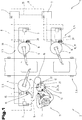
- a technical plant 2 may comprise any further plant components 3 in order to be able to process or execute at least partially automated processes, for example production processes, chemical processes and the like.
- a transport device 6 for the transport of objects, workpieces, semi-finished products and the like between the processing stations 5 and for the provision of objects for the processing stations. 5
- the control system 1 at least one electronic control device 7.
- the at least one control device 7 can also be part of a control network with a plurality of decentralized control devices 7, as also shown schematically in FIG Fig. 1 is indicated.
- the individual control devices 7 can in this case be designed or programmed for carrying out specific tasks, for example for monitoring and controlling the system 1 or for monitoring and controlling certain system components 3, the control architecture for monitoring and controlling the system 2 in principle having any desired topologies can.
- the individual control devices 7 for this purpose can be designed for wired and / or wireless communication via wireless communication links 8 with each other, as shown schematically in FIG Fig. 1 is indicated.
- a wireless communication connection 8 can be formed, for example, by a connection according to the WLAN or bluethooth standard.
- the control system 1 further comprises at least one portable, mobile manual control unit 9.
- the at least one manual control unit 9 or a control device 10 of the manual control unit 9 can in turn signal or data technically connected via a wireless communication link 8 with one or more of the control devices 7 of the control system 1 be.
- the at least one manual control unit 9 is for use provided or formed by an operator 11, in principle, a signal exchange or data exchange between the manual control unit 9 and a control device 7 via the wireless communication link 8 is made possible.
- wired communication links 39 can additionally be provided between the individual control devices 7, 10.
- control device (s) 7 can be functional control device (s) 7 of a system or system component 3, which are designed, for example, to implement automatically transmitted control commands or control commands entered or triggered on the manual control unit 9.
- control devices 7 can be designed, for example, to control actuators or drives for specific system components 3.
- further control devices 7 including, for example, higher-level control devices 7 which, for example, process automated or energy-provisioning processes or transmission processes between individual plant components 3 in an automated or semi-automated manner.
- the at least one manual control unit 9 is communicatively connected to at least one functional control device 7 of the control system 1 in terms of signal transmission technology or data technology.
- the at least one manual control unit 9 has at least one output element 12; for inputting settings and / or for manually triggering control commands, the manual control unit can have input elements 13.
- the respective precise embodiment of the output elements 12 and the input elements 13 of the at least one manual control unit 9 can be adapted to the respective requirements and needs, or the respective application.
- the manual control unit 9 also has an internal power supply unit 14.
- control system 1 at least one formflexibles, material coupling means 15 is provided with a limited, maximum longitudinal extent.
- the control system 1 further comprises at least one spatially fixed, machine-side coupling counterpart 16, wherein the control system 1 in the embodiment according to the Fig. 1 a plurality of mutually distant machine-side coupling counterparts 16 comprises.
- the coupling counterparts 16 are assigned to each locally electrically controllable plant components 3 and electrically controllable machines or electrically controllable machine components.
- each processing station 5 is assigned a coupling counterpart 16.
- At least one tool-operated coupling device 17 is formed, via which coupling device 17, an operator 11 optionally or as needed, a physical bond between the manual control unit 9 and at least one spatially fixed arranged, machine-side coupling counterpart 16 can produce, or solve a manufactured, physical bond again can.
- the coupling device 17 is arranged on the manual control unit 9, and the coupling means 15 on the machine side with the coupling counterpart 16 fixedly connected.
- a further coupling device for coupling the coupling means 15 to the coupling counterpart 16 could also be provided in principle on the machine-side coupling counterpart 16.
- the coupling counterparts 16 each have a material coupling means 15 assigned function-specifically, so that the corresponding coupling counterpart 16 and the corresponding coupling means 15 form a function pair, as is also the case with reference to FIG Fig. 1 illustrated embodiment can be seen.
- a respective coupling means can be designed according to the requirements for a respective coupling counterpart 16. Examples of such functional votes or embodiments of a coupling means 15 and a coupling counterpart 16 will be explained in more detail below with reference to examples.
- a coupling means 15 may be formed in a simple embodiment, for example by a signal inactive means, in particular by a cord, a leash, a tape or a rope. Like in the Fig. 1 is indicated schematically, is in manufactured coupling state of the coupling device 17 by the coupling means 15, the maximum distance within which the operator 11, the hand-held unit 9 can move or remove from the coupling counterpart 16, limited by the longitudinal extent of the coupling means 15.
- the maximum longitudinal extent of a coupling means 15 can basically be chosen freely, and it can usefully be adjusted depending on demand for a maximum for each particular counterpart 16 or system component 3 required or maximum allowable distance of the manual control unit 9 of the coupling counterpart 16.
- a coupling means 15 may have a maximum longitudinal extent selected from a range between 2 meters and 25 meters.
- a coupling means 15 has a maximum longitudinal extent between 5 meters and 15 meters.
- a respective coupling counterpart for this purpose can comprise a storage or holding device 18 for the coupling means 15, in which holding device 18 a coupling means 15 can be spent and stored in a controlled manner.
- the storage or holding device 18 is formed by a winding device 19.
- a winding device 19 may in this case be manually operable, for example.
- a winding device 19 is formed or used, which has a spring-loaded drive or an electric motor drive 20 for winding the coupling means 15.
- the tool-operated coupling device 17, via which the coupling means 15 for establishing a physical bond between the manual control unit 9 and a coupling counterpart 16 can be coupled can basically be designed in a variety of ways.
- a coupling device may be formed by a permanent magnet on the coupling means and a permanent magnet on the hand-held unit, which permanent magnets are designed for mutual attraction.
- the at least one coupling device 17 by a formed on the manual control unit 9 connecting element 21, and by a arranged at one longitudinal end of the at least one coupling means 15 and tool-executable, positive and / or non-positive connection with the connection element 21 provided, corresponding connecting element 22 formed.
- the connecting element 22 may be configured, for example, as a plug, and the connecting element 21, for example, as a corresponding socket for the plug.
- a coupling state monitoring device 23 is formed. Such a coupling state monitoring device 23 may in this case be designed for the continuous detection and monitoring of a mechanical coupling state of the at least one coupling device 17. Additionally or alternatively, a coupling state monitoring device 23 may also be designed for the continuous detection and monitoring of a signal-technical connection state via the coupling means 15 between the manual control unit 9 and the at least one coupling counterpart 16. Examples of different possible embodiments of coupling state monitoring devices 23 will be explained below on the basis of exemplary embodiments. Of course, in principle, a plurality of coupling state monitoring devices 23 may be provided.
- the coupling state monitor 23 may be constituted by a switch contact detecting device 24, as schematically and greatly simplified in FIG Fig. 1 is shown.
- a switching contact detection device 24 may be formed for example for detecting a switching state of a circuit, which circuit can be opened or closed by a connection element 21 associated switching contact when coupling the connecting element 22 or at a disconnection / release of the connecting element 22.
- a corresponding switching contact for example, when coupling the connecting element 22 close the circuit and when detaching the connecting element 22 open the circuit, so that information about the respective coupling state of the coupling device 17 can be obtained in a simple manner by detecting the switching state via a coupling state monitoring device 23 designed as a switching contact detection device 24.
- the at least one coupling state monitoring device 23 can be communicatively connected to the control device 10 of the manual control unit 9, for example, as shown in FIG Fig. 1 is indicated.
- the logical or program-technical processes for enabling or disabling the control commands can be implemented here, for example, in a control device 7 of the control system 1, which is designed to monitor and control the system or system components.
- these processes can also be implemented in a further control device, in particular a safety controller or a safety device 25 for a system component 3, which is connected to the at least one control device 7 in terms of signal or data, as shown schematically in FIG Fig. 1 is apparent.
- a safety controller or a safety device 25 for a system component 3 which is connected to the at least one control device 7 in terms of signal or data, as shown schematically in FIG Fig. 1 is apparent.
- the security device (s) 25 may in turn be communicatively connected to the control devices 7, 10 via a wired or wireless connection.
- control system 1 can be designed to classify all control commands that are critical with regard to personal safety as control-relevant control commands.
- FIG. 2 a further and possibly independent embodiment of the control system 1 is shown in fragmentary form, wherein for like parts the same reference numerals or component designations as in the preceding Fig. 1 be used. To avoid unnecessary repetition, the detailed description in the previous one Fig. 1 referred or referred.
- the coupling state monitoring device 23 is formed by a non-contact detecting sensor device 26 for detecting the presence and / or absence of the connecting member 22 on the terminal member 21.
- a non-contact sensing sensor device 26 may include, for example, magnetic or inductive sensors, for example, eddy current sensors are suitable.
- Optically detecting sensor devices 27 are used for detecting the presence or absence of the connecting element 22.
- At least one connecting element 22 has at least one identifier 28, which comprises or represents identification data about the system component, machine or machine component assigned to the respective coupling counterpart 16.
- the at least one coupling state monitoring device 23, 26, 27 is designed to detect the identifier 28 and to transmit the identifier 28 or the identification data to the at least one control device 7, 10.
- the at least one control device 7, 10 can be subsequently formed on the basis of the transmitted identifier 28 or identification data for signal and / or data assignment and / or release of control-relevant control commands relating to the respectively identified system component, machine or machine component.
- control system 1 can be performed by the control system 1, a secure and unmistakable assignment of wirelessly transmitted control commands, so that in If a triggering of such a control command via the manual control unit 9, from the control system 1 or a control device 7, 10 of the control system 1, a secure assignment of the command to the relevant system component, in the sense of addressing can be made.
- the control system 1 can be designed on the basis of the control commands that are valid and executable for the respectively relevant system component or corresponding control-relevant control commands, as well as for the inhibition of control commands that are not valid or unenforceable for the respective system component.
- the control system 1 can in this case be designed for continuous monitoring of the identifier or the presence of the identifier 28 via at least one coupling state monitoring device 23 or the independent reading device 29.
- the at least one coupling state monitoring device 23 or the independent reading device 29 can be formed by a non-contact reading device, and the respective connecting element 22 can have an identifier 28 detectable by means of the non-contact reading device 23, 29.
- the reading device 23, 29 is formed by an optically detecting sensor device 27, and the respective connecting element 22 has an identifier 28 which can be read by means of the optical sensor device 27.
- the control system 1 or a control device 7, 10 can be subsequently formed on the basis of the transmitted identifier 28 or identification data for automatically or on demand callable output of information relating to the corresponding coupling device 16 associated plant component, machine or machine component on the manual control unit 9.
- FIG. 3 a further and possibly independent embodiment of the control system 1 is shown in fragmentary form, wherein for like parts the same reference numerals or component names as in the preceding Fig. 1 and 2 be used. In order to avoid unnecessary repetition, the detailed description in the previous ones will be used Fig. 1 and 2 referred or referred.
- the coupling means 15 is formed by an electrically conductive cable 30, and the at least one coupling device 17 is formed by an electrical connector 31.
- the coupling means 15 and the cable 30 comprises electrical conductors 32, and the control system 1 in the presence of a physical bond between the manual control unit 9 and the at least one coupling member 16 via the coupling means 15, 30 for electrical power supply of the manual control unit 9 and / or Charging the internal power supply unit 14 of the manual control unit 9 may be formed.
- the at least one coupling state monitoring device 23 is designed for continuous monitoring of an electrically conductive connection between the manual control unit 9 and the at least one coupling counterpart 16.
- a so configured coupling state monitoring device 23 of the coupling remote 16, or the manual control unit 9 may be assigned, or may include the coupling state monitoring device 23 both components at the coupling remote 16 and the manual control unit 9.
- the in the Fig. 3 Coupling state monitoring device 23 shown can be designed, for example, for the continuous testing of a current flow via the coupling means 15 or the electrical cable 30.
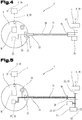
- FIG. 4 a further and possibly independent embodiment of the control system 1 is shown in fragmentary form, wherein for like parts the same reference numerals or component names as in the preceding Fig. 1 to 3 be used. In order to avoid unnecessary repetition, the detailed description in the previous ones will be used Fig. 1 to 3 referred or referred.
- the coupling means 15 comprises at least one signal transmission line 33, so that in the presence of a manufactured coupling state of the coupling device 17 signals between a coupling counterpart 16 and a communicatively connected to the coupling device 16 control device 7 and the manual control unit 9 and the control device 10 of the manual control unit 9 are transferable.
- the signal transmission line (s) 33 can in this case, for example, by optical fibers or be formed by electrical conductors, of course, combinations of light and electrical conductors are possible.
- the at least one coupling state monitoring device 23 is designed for continuous monitoring of a signal connection between the manual control unit 9 and the at least one coupling counterpart 16.
- a coupling state monitoring device 23 designed in this way can be assigned to the coupling remote 16 or the manual control unit 9, or the coupling state monitoring device 23 can comprise both components at the coupling remote 16 and the manual control unit 9.
- the in the Fig. 4 Coupling state monitoring device 23 shown may be designed, for example, for the continuous testing of a signal transmission via the coupling means 15.
- the control system 1 can also be designed to transmit or provide a data-technical identifier via the at least one signal transmission line 33 to the manual control unit 9 or the control device 10 of the manual control unit 9.
- a corresponding data-technical identifier may for example be stored or stored in an electronic memory unit 34 assigned to the coupling remote 16.
- Such a data-technical identifier may in turn comprise identification data about the system component, machine or machine component assigned to the respective coupling remote station 16, and the manual control unit 9 or the control device 10 of the manual control unit 9 on the basis of the transmitted data-technical identifier or the identification data for the signal and / or be formed data-related assignment and / or release of supervisory control commands relating to each identified plant component, machine or machine component.
- the control system 1 can perform in this way, for example, a secure and unmistakable assignment of wirelessly transmitted control commands, so that in the case of triggering such a control command via the manual control unit 9, the control system 1 and a control device 7, 10 of the control system. 1 a secure assignment of the command to the relevant system component, in the sense of addressing can be made. An additional selection step beyond the mere coupling process on the part of the user is thereby unnecessary. This also reliably prevents erroneous allocation, for example, due to erroneous user input or due to an error on the part of an operator, for example when selecting one of several machines.
- the control system 1 can be designed on the basis of the control commands that are valid and executable for the respectively relevant system component or corresponding control-relevant control commands, as well as for the inhibition of control commands that are not valid or unenforceable for the respective system component.
- a design variant of the control system 1 is possible, in which the hand-held unit 9 based on the at least one signal transmission line 33 of the coupling means 15 transmitted data-technical identifier or identification data for automatic or, if necessary, callable output of information regarding the corresponding coupling counterpart 16 associated plant components, machines or machine components is formed on the manual control unit 9.
- control system 1 in the presence of a physical and signaling connection via the at least one coupling means 15 between the manual control unit 9 and a coupling counterpart 16 for transmitting the control-relevant control commands from the manual control unit 9 or the control device 10th the hand-held unit 9 to the at least one control device 7 via the at least one coupling means 15 and the signal transmission line (s) 33 of the coupling means 15 and via the coupling counterpart 16 is formed, as in the Fig. 4 is indicated schematically.
- provision can be made, for example, for the control system 1 to be designed to transmit the control commands using a real-time-capable bus protocol and / or using a safety-related bus protocol. Examples of such bus protocols include EtherCAT, Safety-over-EtherCAT, ProfiNET or Profibus.
- the manual control unit 9 at least one manually triggerable safety switching element 35, as shown in the Fig. 5 is shown.
- FIG. 5 a further and possibly independent embodiment of the control system 1 is shown in fragmentary form, wherein for like parts the same reference numerals or component names as in the preceding Fig. 1 to 4 be used. In order to avoid unnecessary repetition, the detailed description in the previous ones will be used Fig. 1 to 4 referred or referred.
- safety switching element 35 on the manual control unit 9 may be formed for example by a so-called, possibly multi-stage enabling button.
- the manual control unit preferably has at least one safety switching element 35 designed as an emergency stop or emergency stop switch.
- the control system 1 in the presence of such a safety switching element 35 on the manual control unit 9, the control system 1 in the presence of a physical and signaling connection based on a suitably designed coupling means 15 between the manual control unit 9 and the coupling remote 16, and at manual triggering of the safety switching element 35 for transmitting or providing a security signal be formed on the basis of the manual control unit 9 to the at least one control device 7 or to a separately configured safety device 25 via the coupling means 15 and the coupling counterpart 16, as shown schematically in the Fig. 5 is apparent.
- the safety device can in this case be designed, for example, to immediately stop machine components via safety control lines 40, or, for example, to completely shut down a system component or machine.
- the signaling connection based on the coupling means 15 between the manual control unit 9 and the coupling counterpart 16 may comprise a so-called safety circuit 36 which can be triggered directly via corresponding NC contacts via the safety switching element 35, for example an emergency stop switch.
- a safety circuit 36 can be dual-circuited, and thus failsafe, as shown in FIG Fig. 5 is indicated schematically.
- the at least one coupling state monitoring device 23 for continuously monitoring the proper signal connection between the safety switching element 35 of the manual control unit 9 and the at least one control device 7 or between the safety switching element 35 of the manual control unit 9 and the separately configured security device 25 is formed.
- the coupling state monitoring device 23 comprises a safety circuit 37 at the coupling remote 16, which for periodic short-circuit and cross-fault testing of the proper signal connection between the safety switching element 35 of the manual control unit 9 and the at least one control device 7 or between the safety switching element 35 of the manual control unit and the separately configured security device 25 is formed.
- the coupling state monitoring device 23 may comprise a further, formed on the manual control unit 9 safety circuit 38, which is designed for continuous verification of the periodic short-circuit and cross-circuit checks of the safety circuit 37 at the coupling counterpart 16.
Landscapes
- Engineering & Computer Science (AREA)
- Mechanical Engineering (AREA)
- Robotics (AREA)
- Automation & Control Theory (AREA)
- Physics & Mathematics (AREA)
- General Physics & Mathematics (AREA)
- Computer Networks & Wireless Communication (AREA)
- General Engineering & Computer Science (AREA)
- Manufacturing & Machinery (AREA)
- Quality & Reliability (AREA)
- Safety Devices In Control Systems (AREA)
- Selective Calling Equipment (AREA)
- Testing And Monitoring For Control Systems (AREA)
Claims (20)
- Système de commande (1) pour des installations à commande électrique, comprenant au moins un dispositif de commande (7) électronique destiné à la surveillance et à la commande d'une installation (2) et/ou de composantes d'installation (3),
au moins une unité de manoeuvre (9) portable mobile destinée à l'affichage d'informations et à l'entrée d'instructions de commande, avec une unité d'alimentation en courant (14) interne pour l'alimentation en courant électrique temporaire de l'unité de manoeuvre (9),
un raccordement de communication (8) sans fil entre l'au moins un dispositif de commande (7) et l'unité de manoeuvre (9) pour la transmission d'informations et d'instructions de commande entre l'unité de manoeuvre (9) et le dispositif de commande (7),
dans lequel il est prévu au moins un moyen de couplage (15) matériel de forme flexible avec une extension longitudinale maximale limitée, lequel moyen de couplage (15) est prévu, via au moins un dispositif de couplage (17) actionnable sans outil, pour au choix l'établissement et la suppression d'une liaison physique entre l'unité de manoeuvre (9) et au moins un poste homologue de couplage (16) côté machine disposé de façon stationnaire dans l'espace,
caractérisé en ce qu'il est constitué un dispositif de surveillance de l'état de couplage (23) destiné à la détection et surveillance continues d'un état de couplage mécanique de l'au moins un dispositif de couplage (17) et/ou destiné à la détection et surveillance continues d'un état de raccordement par signaux via le moyen de couplage (15) entre l'unité de manoeuvre (9) et l'au moins un poste homologue de couplage (16),
dans lequel le système de commande (1) est constitué pour la validation de l'entrée d'instructions de commande importantes pour le contrôle, en particulier devant être surveillées directement par un opérateur, au niveau de l'unité de manoeuvre en cas de détection d'un état de couplage établi ou d'un état de raccordement existant, et pour le blocage de l'entrée de l'instruction de commande importante pour le contrôle via l'unité de manoeuvre en cas de détection d'un état de couplage supprimé ou d'un état de raccordement interrompu. - Système de commande selon la revendication 1, caractérisé en ce que le moyen de couplage (15) présente une extension longitudinale maximale sélectionnée dans une plage entre 2 mètres et 25 mètres.
- Système de commande selon l'une des revendications 1 ou 2, caractérisé en ce qu'au moins toutes les instructions de commande critiques en matière de sécurité des personnes sont classées en tant qu'instructions de commande importantes pour le contrôle.
- Système de commande selon l'une des revendications précédentes, caractérisé en ce que l'au moins un dispositif de couplage (17) est formé par un élément de connexion (21) constitué sur l'unité de manoeuvre (9), ainsi que par un élément de raccordement (22) disposé à une extrémité longitudinale de l'au moins un moyen de couplage (15) et prévu pour le raccordement à l'élément de connexion (21), réalisable sans outil, par liaison de forme et/ou de force.
- Système de commande selon la revendication 4, caractérisé en ce que le dispositif de surveillance de l'état de couplage (23) est constitué par un dispositif de détection de contact de commutation (24) électrique destiné à la détection d'un élément de raccordement (22) couplé à l'élément de connexion (21).
- Système de commande selon la revendication 4, caractérisé en ce que le dispositif de surveillance de l'état de couplage (23) est constitué par un dispositif de capteur (26) à détection sans contact destiné à la détection de la présence et/ou de l'absence de l'élément de raccordement (22) au niveau de l'élément de connexion (21).
- Système de commande selon l'une des revendications précédentes, caractérisé en ce qu'il comprend plusieurs postes homologues de couplage (16) côté machine espacés les uns des autres, postes homologues de couplage (16) auxquels sont affectées respectivement localement des composantes d'installation (3) à commande électrique ou machines à commande électrique ou composantes de machine à commande électrique.
- Système de commande selon la revendication 7, caractérisé en ce qu'un moyen de couplage (15) matériel est affecté, de façon fonctionnellement spécifique, à au moins un des postes homologues de couplage (16) de telle sorte que le poste homologue de couplage (16) correspondant et le moyen de couplage (15) correspondant constituent une paire fonctionnelle.
- Système de commande selon la revendication 8, caractérisé en ce que l'extension longitudinale maximale d'un moyen de couplage (15) respectif est adaptée en ce qui concerne un espacement nécessaire maximal ou admissible maximal de l'unité de manoeuvre (9) par rapport au poste homologue de couplage (16).
- Système de commande selon l'une des revendications 4 à 9, caractérisé en ce qu'au moins un élément de raccordement (22) comporte au moins un identifiant (28) qui comprend ou représente des données d'identification portant sur la composante d'installation (3), machine ou composante de machine affectée au poste homologue de couplage (16) respectif, et en ce que l'au moins un dispositif de surveillance de l'état de couplage (23) ou un dispositif de lecture (29) autonome est constitué pour la détection de l'identifiant (28) et pour la transmission de l'identifiant (28) ou des données d'identification à l'au moins un dispositif de commande (7, 10), et en ce que le dispositif de commande (7, 10) est, sur la base de l'identifiant (28) ou des données d'identification transmis(es), constitué pour l'affectation et/ou validation, par signaux et/ou informatisée, d'instructions de commande importantes pour le contrôle concernant la composante d'installation (3), machine ou composante de machine respectivement identifiée.
- Système de commande selon la revendication 10, caractérisé en ce que, sur la base de l'identifiant (28) ou des données d'identification transmis(es), ce système est constitué pour la production, automatique ou appelable en fonction des besoins, d'informations concernant la composante d'installation (3), machine ou composante de machine affectée au poste homologue de couplage (16) correspondant, au niveau de l'unité de manoeuvre.
- Système de commande selon l'une des revendications précédentes, caractérisé en ce que le moyen de couplage (15) est formé par un câble (30) électriquement conducteur, et l'au moins un dispositif de couplage (17) est formé par une connexion enfichable (31) électrique, dans lequel le système de commande, en présence d'une liaison physique entre l'unité de manoeuvre (9) et l'au moins un poste homologue de couplage (16) via le moyen de couplage (15), est constitué pour l'alimentation en courant électrique de l'unité de manoeuvre (9) et/ou pour le chargement de l'unité d'alimentation électrique (14) interne de l'unité de manoeuvre (9).
- Système de commande selon l'une des revendications précédentes, caractérisé en ce que le moyen de couplage (15) comprend au moins une ligne de transmission de signaux (33).
- Système de commande selon la revendication 12 ou 13, caractérisé en ce que l'au moins un dispositif de surveillance de l'état de couplage (23) est constitué pour la surveillance continue d'un raccordement électriquement conducteur et/ou pour la surveillance continue d'un raccordement par signaux entre l'unité de manoeuvre (9) et l'au moins un poste homologue de couplage (16).
- Système de commande selon la revendication 13 ou 14, caractérisé en ce qu'il est constitué pour la transmission à l'unité de manoeuvre (9) d'un identifiant (28) informatisé via l'au moins une ligne de transmission de signaux (33), lequel identifiant informatisé comprend des données d'identification portant sur la composante d'installation (3), machine ou composante de machine affectée au poste homologue de couplage (16) respectif, et en ce que, sur la base de l'identifiant ou des données d'identification transmis(es), l'unité de manoeuvre (9) est constituée pour l'affectation et/ou validation, par signaux et/ou informatisée, d'instructions de commande importantes pour le contrôle concernant la composante d'installation (3), machine ou composante de machine respectivement identifiée.
- Système de commande selon la revendication 15, caractérisé en ce que, sur la base de l'identifiant informatisé ou de données d'identification transmis(es), l'unité de manoeuvre (9) est constituée pour la production, automatique ou appelable en fonction des besoins, d'informations concernant les composantes d'installation (3), machines ou composantes de machine affectées au poste homologue de couplage (16) correspondant, au niveau de l'unité de manoeuvre (9).
- Système de commande selon l'une des revendications 13 à 16, caractérisé en ce que, en présence d'un raccordement physique et par signaux par le biais de l'au moins un moyen de couplage (15) entre l'unité de manoeuvre (9) et un poste homologue de couplage (16), le système de commande est constitué pour la transmission des instructions de commande importantes pour le contrôle à partir de l'unité de manoeuvre (9) à destination de l'au moins un dispositif de commande (7) via l'au moins un moyen de couplage (15) et le poste homologue de couplage (16).
- Système de commande selon l'une des revendications 13 à 17, caractérisé en ce que l'unité de manoeuvre (9) comporte au moins un élément de commutation de sécurité (35) pouvant être déclenché manuellement, et en ce que, en présence d'un raccordement physique ou par signaux, à l'aide d'un moyen de couplage (15) entre l'unité de manoeuvre (9) et le poste homologue de couplage (16), et en cas de déclenchement manuel de l'élément de commutation de sécurité (35), le système de commande (1) est constitué pour la transmission d'un signal de sécurité via le moyen de couplage (15) et le poste homologue de couplage (16) en partant de l'unité de manoeuvre (9) à destination de l'au moins un dispositif de commande (7) ou à destination d'un dispositif de sécurité (25) configuré séparément, dans lequel l'au moins un dispositif de surveillance de l'état de couplage (23) est constitué pour la surveillance continue de la conformité de la liaison par signaux entre l'élément de commutation de sécurité (35) de l'unité de manoeuvre (9) et l'au moins un dispositif de commande (7), ou entre l'élément de commutation de sécurité (35) de l'unité de manoeuvre (9) et le dispositif de sécurité (25) configuré séparément.
- Système de commande selon l'une des revendications 1 à 11, caractérisé en ce que l'au moins un moyen de couplage (15) est formé par un moyen inactif au niveau signalisation, en particulier par une ficelle, une corde, un ruban ou un cordage.
- Système de commande selon l'une des revendications précédentes, caractérisé en ce que l'au moins un poste distant de couplage (16) comprend un dispositif de rangement ou de retenue (18) pour le moyen de couplage (15).
Applications Claiming Priority (2)
| Application Number | Priority Date | Filing Date | Title |
|---|---|---|---|
| ATA50951/2015A AT517928A2 (de) | 2015-11-06 | 2015-11-06 | Steuerungssystem für elektrisch gesteuerte Anlagen |
| PCT/EP2016/076066 WO2017076765A1 (fr) | 2015-11-06 | 2016-10-28 | Système de commande d'installations à commande électrique |
Publications (2)
| Publication Number | Publication Date |
|---|---|
| EP3371663A1 EP3371663A1 (fr) | 2018-09-12 |
| EP3371663B1 true EP3371663B1 (fr) | 2019-10-02 |
Family
ID=57208309
Family Applications (1)
| Application Number | Title | Priority Date | Filing Date |
|---|---|---|---|
| EP16787892.5A Active EP3371663B1 (fr) | 2015-11-06 | 2016-10-28 | Système de commande d'installations à commande électrique |
Country Status (5)
| Country | Link |
|---|---|
| US (1) | US10649431B2 (fr) |
| EP (1) | EP3371663B1 (fr) |
| CN (1) | CN108369402B (fr) |
| AT (1) | AT517928A2 (fr) |
| WO (1) | WO2017076765A1 (fr) |
Families Citing this family (4)
| Publication number | Priority date | Publication date | Assignee | Title |
|---|---|---|---|---|
| NZ761028A (en) * | 2017-09-26 | 2025-11-28 | Delaval Holding Ab | Control system, method and computer program for an automatic milking machine |
| JP7263724B2 (ja) * | 2018-09-27 | 2023-04-25 | 株式会社デンソーウェーブ | ロボットの制御方法 |
| AT521871B1 (de) * | 2018-10-31 | 2021-10-15 | Keba Ag | Verfahren zum Betreiben eines Maschinensteuerungssystems sowie Maschinensteuerungssystem |
| JP7205972B2 (ja) * | 2019-05-24 | 2023-01-17 | 川崎重工業株式会社 | 教示システム |
Family Cites Families (11)
| Publication number | Priority date | Publication date | Assignee | Title |
|---|---|---|---|---|
| US5491774A (en) * | 1994-04-19 | 1996-02-13 | Comp General Corporation | Handheld record and playback device with flash memory |
| WO2003088011A2 (fr) | 2002-04-12 | 2003-10-23 | Keba Ag | Unite de calcul mobile et dispositif d'extension pour commande de machines industrielles |
| US7581119B2 (en) * | 2004-07-18 | 2009-08-25 | Apple Inc. | Method and system for discovering a power source on a peripheral bus |
| DE102004050908A1 (de) | 2004-10-19 | 2006-05-18 | Siemens Ag | Vorrichtung zur Kommunikation mit einer Anlage |
| AT501688B1 (de) * | 2005-04-08 | 2008-02-15 | Keba Ag | Verfahren sowie vorrichtung zur sicheren, verwechslungsfreien und ausschliesslichen zuordnung der befehlsgewalt einer bedienperson zu einer steuerbaren technischen einrichtung |
| DE602005006749D1 (de) * | 2005-04-19 | 2008-06-26 | Comau Spa | Verfahren zur Steuerung von industriellen Robotern und entsprechend gesteuerte Roboter, Robotersysteme und Computerprogramme |
| DE112007000394T5 (de) | 2006-02-14 | 2008-12-24 | Kabushiki Kaisha Yaskawa Denki, Kitakyushu | Robotersystem |
| EP2255932B1 (fr) * | 2008-03-28 | 2015-03-04 | Daihen Corporation | Système de commande de robot |
| AT10676U1 (de) * | 2008-07-21 | 2009-08-15 | Keba Ag | Verfahren zum betreiben eines mobilen handbediengerätes für die abgabe oder freischaltung von potentiell gefahrbringenden steuerkommandos sowie entsprechendes handbediengerät |
| WO2013065795A1 (fr) * | 2011-11-02 | 2013-05-10 | 株式会社Ihi | Dispositif pour retirer des débris spatiaux et procédé pour retirer des débris spatiaux |
| US10035269B2 (en) * | 2015-09-16 | 2018-07-31 | The Boeing Company | Enhanced robotic teaching tool |
-
2015
- 2015-11-06 AT ATA50951/2015A patent/AT517928A2/de not_active Application Discontinuation
-
2016
- 2016-10-28 CN CN201680072461.7A patent/CN108369402B/zh active Active
- 2016-10-28 WO PCT/EP2016/076066 patent/WO2017076765A1/fr not_active Ceased
- 2016-10-28 US US15/773,600 patent/US10649431B2/en active Active
- 2016-10-28 EP EP16787892.5A patent/EP3371663B1/fr active Active
Also Published As
| Publication number | Publication date |
|---|---|
| US10649431B2 (en) | 2020-05-12 |
| CN108369402A (zh) | 2018-08-03 |
| EP3371663A1 (fr) | 2018-09-12 |
| CN108369402B (zh) | 2021-01-12 |
| US20190079482A1 (en) | 2019-03-14 |
| AT517928A2 (de) | 2017-05-15 |
| WO2017076765A1 (fr) | 2017-05-11 |
Similar Documents
| Publication | Publication Date | Title |
|---|---|---|
| EP1866712B1 (fr) | Procedes et dispositifs permettant d'attribuer le commandement d'un operateur a un dispositif technique a commande de façon fiable, exclusive et sans confusion | |
| DE10110776B4 (de) | Verfahren zur Zuordnung einer mobilen Bedien- und/oder Beobachtungseinrichtung zu einer Maschine sowie Bedien- und/oder Beobachtungseinrichtung hierfür | |
| EP0243811B1 (fr) | Dispositif de commande de rotatives d'impression | |
| EP2577414B1 (fr) | Procédé et système de commande pour programmer ou prescrire des mouvements ou processus d'un robot industriel | |
| EP3371663B1 (fr) | Système de commande d'installations à commande électrique | |
| AT519161B1 (de) | Verfahren zum Betreiben eines industriellen Steuerungssystems sowie entsprechendes Steuerungssystem | |
| EP1655645A2 (fr) | Dispositif destiné à la communication avec une installation | |
| EP1899770B1 (fr) | Procede permettant d'etablir, d'interrompre et de faire fonctionner une liaison active intermittente entre un dispositif de commande mobile et un dispositif pouvant etre commande, et poste correspondant de transmission de donnees sure | |
| AT521872A1 (de) | Verfahren zum Betreiben eines Maschinensteuerungssystems sowie entsprechendes Maschinensteuerungssystem | |
| WO2020087101A1 (fr) | Procédé pour faire fonctionner un système de commande de machine et système de commande de machine correspondant | |
| WO2006102691A2 (fr) | Dispositif de transport a commande repartie electrique pour produits en piece a transporter et systeme de transport correspondant | |
| AT504670B1 (de) | Verfahren zum betreiben einer drahtlosen kommunikationsverbindung zwischen einem mobilen handbediengerät und einer maschinensteuerung sowie entsprechende systemkomponenten | |
| EP1665191A1 (fr) | Systeme hmi dote d'un appareil de commande et d'observation mobile pour des commandes de securite d'une installation technique | |
| EP3631587B1 (fr) | Procédé de fonctionnement d'une installation de production et installation de production | |
| AT518665B1 (de) | Steuerungssystem für elektrisch gesteuerte Anlagen | |
| EP1519336B1 (fr) | Dispositif pour communiquer avec un équipement | |
| EP1664950B1 (fr) | Dispositif pour communiquer avec un appareil | |
| EP3717974B1 (fr) | Procédé destiné à faire fonctionner un système de commande de machine et système de commande de machine correspondant | |
| WO2017072246A1 (fr) | Système de commande pour la commande sécurisée de machines | |
| WO2015055668A1 (fr) | Commande mobile d'installations |
Legal Events
| Date | Code | Title | Description |
|---|---|---|---|
| STAA | Information on the status of an ep patent application or granted ep patent |
Free format text: STATUS: UNKNOWN |
|
| STAA | Information on the status of an ep patent application or granted ep patent |
Free format text: STATUS: THE INTERNATIONAL PUBLICATION HAS BEEN MADE |
|
| PUAI | Public reference made under article 153(3) epc to a published international application that has entered the european phase |
Free format text: ORIGINAL CODE: 0009012 |
|
| STAA | Information on the status of an ep patent application or granted ep patent |
Free format text: STATUS: REQUEST FOR EXAMINATION WAS MADE |
|
| 17P | Request for examination filed |
Effective date: 20180604 |
|
| AK | Designated contracting states |
Kind code of ref document: A1 Designated state(s): AL AT BE BG CH CY CZ DE DK EE ES FI FR GB GR HR HU IE IS IT LI LT LU LV MC MK MT NL NO PL PT RO RS SE SI SK SM TR |
|
| AX | Request for extension of the european patent |
Extension state: BA ME |
|
| DAV | Request for validation of the european patent (deleted) | ||
| DAX | Request for extension of the european patent (deleted) | ||
| GRAP | Despatch of communication of intention to grant a patent |
Free format text: ORIGINAL CODE: EPIDOSNIGR1 |
|
| STAA | Information on the status of an ep patent application or granted ep patent |
Free format text: STATUS: GRANT OF PATENT IS INTENDED |
|
| INTG | Intention to grant announced |
Effective date: 20190423 |
|
| GRAS | Grant fee paid |
Free format text: ORIGINAL CODE: EPIDOSNIGR3 |
|
| GRAA | (expected) grant |
Free format text: ORIGINAL CODE: 0009210 |
|
| STAA | Information on the status of an ep patent application or granted ep patent |
Free format text: STATUS: THE PATENT HAS BEEN GRANTED |
|
| AK | Designated contracting states |
Kind code of ref document: B1 Designated state(s): AL AT BE BG CH CY CZ DE DK EE ES FI FR GB GR HR HU IE IS IT LI LT LU LV MC MK MT NL NO PL PT RO RS SE SI SK SM TR |
|
| REG | Reference to a national code |
Ref country code: GB Ref legal event code: FG4D Free format text: NOT ENGLISH |
|
| REG | Reference to a national code |
Ref country code: CH Ref legal event code: EP Ref country code: AT Ref legal event code: REF Ref document number: 1186883 Country of ref document: AT Kind code of ref document: T Effective date: 20191015 |
|
| REG | Reference to a national code |
Ref country code: DE Ref legal event code: R096 Ref document number: 502016006935 Country of ref document: DE |
|
| REG | Reference to a national code |
Ref country code: IE Ref legal event code: FG4D Free format text: LANGUAGE OF EP DOCUMENT: GERMAN |
|
| REG | Reference to a national code |
Ref country code: NL Ref legal event code: MP Effective date: 20191002 |
|
| REG | Reference to a national code |
Ref country code: LT Ref legal event code: MG4D |
|
| PG25 | Lapsed in a contracting state [announced via postgrant information from national office to epo] |
Ref country code: BG Free format text: LAPSE BECAUSE OF FAILURE TO SUBMIT A TRANSLATION OF THE DESCRIPTION OR TO PAY THE FEE WITHIN THE PRESCRIBED TIME-LIMIT Effective date: 20200102 Ref country code: FI Free format text: LAPSE BECAUSE OF FAILURE TO SUBMIT A TRANSLATION OF THE DESCRIPTION OR TO PAY THE FEE WITHIN THE PRESCRIBED TIME-LIMIT Effective date: 20191002 Ref country code: NO Free format text: LAPSE BECAUSE OF FAILURE TO SUBMIT A TRANSLATION OF THE DESCRIPTION OR TO PAY THE FEE WITHIN THE PRESCRIBED TIME-LIMIT Effective date: 20200102 Ref country code: GR Free format text: LAPSE BECAUSE OF FAILURE TO SUBMIT A TRANSLATION OF THE DESCRIPTION OR TO PAY THE FEE WITHIN THE PRESCRIBED TIME-LIMIT Effective date: 20200103 Ref country code: PT Free format text: LAPSE BECAUSE OF FAILURE TO SUBMIT A TRANSLATION OF THE DESCRIPTION OR TO PAY THE FEE WITHIN THE PRESCRIBED TIME-LIMIT Effective date: 20200203 Ref country code: LV Free format text: LAPSE BECAUSE OF FAILURE TO SUBMIT A TRANSLATION OF THE DESCRIPTION OR TO PAY THE FEE WITHIN THE PRESCRIBED TIME-LIMIT Effective date: 20191002 Ref country code: SE Free format text: LAPSE BECAUSE OF FAILURE TO SUBMIT A TRANSLATION OF THE DESCRIPTION OR TO PAY THE FEE WITHIN THE PRESCRIBED TIME-LIMIT Effective date: 20191002 Ref country code: NL Free format text: LAPSE BECAUSE OF FAILURE TO SUBMIT A TRANSLATION OF THE DESCRIPTION OR TO PAY THE FEE WITHIN THE PRESCRIBED TIME-LIMIT Effective date: 20191002 Ref country code: PL Free format text: LAPSE BECAUSE OF FAILURE TO SUBMIT A TRANSLATION OF THE DESCRIPTION OR TO PAY THE FEE WITHIN THE PRESCRIBED TIME-LIMIT Effective date: 20191002 Ref country code: LT Free format text: LAPSE BECAUSE OF FAILURE TO SUBMIT A TRANSLATION OF THE DESCRIPTION OR TO PAY THE FEE WITHIN THE PRESCRIBED TIME-LIMIT Effective date: 20191002 Ref country code: ES Free format text: LAPSE BECAUSE OF FAILURE TO SUBMIT A TRANSLATION OF THE DESCRIPTION OR TO PAY THE FEE WITHIN THE PRESCRIBED TIME-LIMIT Effective date: 20191002 |
|
| PG25 | Lapsed in a contracting state [announced via postgrant information from national office to epo] |
Ref country code: IS Free format text: LAPSE BECAUSE OF FAILURE TO SUBMIT A TRANSLATION OF THE DESCRIPTION OR TO PAY THE FEE WITHIN THE PRESCRIBED TIME-LIMIT Effective date: 20200224 Ref country code: CZ Free format text: LAPSE BECAUSE OF FAILURE TO SUBMIT A TRANSLATION OF THE DESCRIPTION OR TO PAY THE FEE WITHIN THE PRESCRIBED TIME-LIMIT Effective date: 20191002 Ref country code: HR Free format text: LAPSE BECAUSE OF FAILURE TO SUBMIT A TRANSLATION OF THE DESCRIPTION OR TO PAY THE FEE WITHIN THE PRESCRIBED TIME-LIMIT Effective date: 20191002 Ref country code: RS Free format text: LAPSE BECAUSE OF FAILURE TO SUBMIT A TRANSLATION OF THE DESCRIPTION OR TO PAY THE FEE WITHIN THE PRESCRIBED TIME-LIMIT Effective date: 20191002 |
|
| REG | Reference to a national code |
Ref country code: CH Ref legal event code: PL |
|
| PG25 | Lapsed in a contracting state [announced via postgrant information from national office to epo] |
Ref country code: AL Free format text: LAPSE BECAUSE OF FAILURE TO SUBMIT A TRANSLATION OF THE DESCRIPTION OR TO PAY THE FEE WITHIN THE PRESCRIBED TIME-LIMIT Effective date: 20191002 |
|
| REG | Reference to a national code |
Ref country code: DE Ref legal event code: R097 Ref document number: 502016006935 Country of ref document: DE |
|
| PG2D | Information on lapse in contracting state deleted |
Ref country code: IS |
|
| PG25 | Lapsed in a contracting state [announced via postgrant information from national office to epo] |
Ref country code: MC Free format text: LAPSE BECAUSE OF FAILURE TO SUBMIT A TRANSLATION OF THE DESCRIPTION OR TO PAY THE FEE WITHIN THE PRESCRIBED TIME-LIMIT Effective date: 20191002 Ref country code: LU Free format text: LAPSE BECAUSE OF NON-PAYMENT OF DUE FEES Effective date: 20191028 Ref country code: LI Free format text: LAPSE BECAUSE OF NON-PAYMENT OF DUE FEES Effective date: 20191031 Ref country code: RO Free format text: LAPSE BECAUSE OF FAILURE TO SUBMIT A TRANSLATION OF THE DESCRIPTION OR TO PAY THE FEE WITHIN THE PRESCRIBED TIME-LIMIT Effective date: 20191002 Ref country code: CH Free format text: LAPSE BECAUSE OF NON-PAYMENT OF DUE FEES Effective date: 20191031 Ref country code: EE Free format text: LAPSE BECAUSE OF FAILURE TO SUBMIT A TRANSLATION OF THE DESCRIPTION OR TO PAY THE FEE WITHIN THE PRESCRIBED TIME-LIMIT Effective date: 20191002 Ref country code: DK Free format text: LAPSE BECAUSE OF FAILURE TO SUBMIT A TRANSLATION OF THE DESCRIPTION OR TO PAY THE FEE WITHIN THE PRESCRIBED TIME-LIMIT Effective date: 20191002 Ref country code: IS Free format text: LAPSE BECAUSE OF FAILURE TO SUBMIT A TRANSLATION OF THE DESCRIPTION OR TO PAY THE FEE WITHIN THE PRESCRIBED TIME-LIMIT Effective date: 20200202 |
|
| PLBE | No opposition filed within time limit |
Free format text: ORIGINAL CODE: 0009261 |
|
| STAA | Information on the status of an ep patent application or granted ep patent |
Free format text: STATUS: NO OPPOSITION FILED WITHIN TIME LIMIT |
|
| REG | Reference to a national code |
Ref country code: BE Ref legal event code: MM Effective date: 20191031 |
|
| PG25 | Lapsed in a contracting state [announced via postgrant information from national office to epo] |
Ref country code: BE Free format text: LAPSE BECAUSE OF NON-PAYMENT OF DUE FEES Effective date: 20191031 Ref country code: IT Free format text: LAPSE BECAUSE OF FAILURE TO SUBMIT A TRANSLATION OF THE DESCRIPTION OR TO PAY THE FEE WITHIN THE PRESCRIBED TIME-LIMIT Effective date: 20191002 Ref country code: SM Free format text: LAPSE BECAUSE OF FAILURE TO SUBMIT A TRANSLATION OF THE DESCRIPTION OR TO PAY THE FEE WITHIN THE PRESCRIBED TIME-LIMIT Effective date: 20191002 Ref country code: SK Free format text: LAPSE BECAUSE OF FAILURE TO SUBMIT A TRANSLATION OF THE DESCRIPTION OR TO PAY THE FEE WITHIN THE PRESCRIBED TIME-LIMIT Effective date: 20191002 |
|
| 26N | No opposition filed |
Effective date: 20200703 |
|
| PG25 | Lapsed in a contracting state [announced via postgrant information from national office to epo] |
Ref country code: FR Free format text: LAPSE BECAUSE OF NON-PAYMENT OF DUE FEES Effective date: 20191202 Ref country code: IE Free format text: LAPSE BECAUSE OF NON-PAYMENT OF DUE FEES Effective date: 20191028 |
|
| PG25 | Lapsed in a contracting state [announced via postgrant information from national office to epo] |
Ref country code: SI Free format text: LAPSE BECAUSE OF FAILURE TO SUBMIT A TRANSLATION OF THE DESCRIPTION OR TO PAY THE FEE WITHIN THE PRESCRIBED TIME-LIMIT Effective date: 20191002 |
|
| PG25 | Lapsed in a contracting state [announced via postgrant information from national office to epo] |
Ref country code: CY Free format text: LAPSE BECAUSE OF FAILURE TO SUBMIT A TRANSLATION OF THE DESCRIPTION OR TO PAY THE FEE WITHIN THE PRESCRIBED TIME-LIMIT Effective date: 20191002 |
|
| GBPC | Gb: european patent ceased through non-payment of renewal fee |
Effective date: 20201028 |
|
| PG25 | Lapsed in a contracting state [announced via postgrant information from national office to epo] |
Ref country code: HU Free format text: LAPSE BECAUSE OF FAILURE TO SUBMIT A TRANSLATION OF THE DESCRIPTION OR TO PAY THE FEE WITHIN THE PRESCRIBED TIME-LIMIT; INVALID AB INITIO Effective date: 20161028 Ref country code: MT Free format text: LAPSE BECAUSE OF FAILURE TO SUBMIT A TRANSLATION OF THE DESCRIPTION OR TO PAY THE FEE WITHIN THE PRESCRIBED TIME-LIMIT Effective date: 20191002 |
|
| PG25 | Lapsed in a contracting state [announced via postgrant information from national office to epo] |
Ref country code: GB Free format text: LAPSE BECAUSE OF NON-PAYMENT OF DUE FEES Effective date: 20201028 |
|
| REG | Reference to a national code |
Ref country code: DE Ref legal event code: R081 Ref document number: 502016006935 Country of ref document: DE Owner name: KEBA INDUSTRIAL AUTOMATION GMBH, AT Free format text: FORMER OWNER: KEBA AG, LINZ, AT |
|
| PG25 | Lapsed in a contracting state [announced via postgrant information from national office to epo] |
Ref country code: TR Free format text: LAPSE BECAUSE OF FAILURE TO SUBMIT A TRANSLATION OF THE DESCRIPTION OR TO PAY THE FEE WITHIN THE PRESCRIBED TIME-LIMIT Effective date: 20191002 |
|
| PG25 | Lapsed in a contracting state [announced via postgrant information from national office to epo] |
Ref country code: MK Free format text: LAPSE BECAUSE OF FAILURE TO SUBMIT A TRANSLATION OF THE DESCRIPTION OR TO PAY THE FEE WITHIN THE PRESCRIBED TIME-LIMIT Effective date: 20191002 |
|
| REG | Reference to a national code |
Ref country code: AT Ref legal event code: MM01 Ref document number: 1186883 Country of ref document: AT Kind code of ref document: T Effective date: 20211028 |
|
| PG25 | Lapsed in a contracting state [announced via postgrant information from national office to epo] |
Ref country code: AT Free format text: LAPSE BECAUSE OF NON-PAYMENT OF DUE FEES Effective date: 20211028 |
|
| PGFP | Annual fee paid to national office [announced via postgrant information from national office to epo] |
Ref country code: DE Payment date: 20251024 Year of fee payment: 10 |