EP0808039A2 - Interface optique - Google Patents
Interface optique Download PDFInfo
- Publication number
- EP0808039A2 EP0808039A2 EP19970107311 EP97107311A EP0808039A2 EP 0808039 A2 EP0808039 A2 EP 0808039A2 EP 19970107311 EP19970107311 EP 19970107311 EP 97107311 A EP97107311 A EP 97107311A EP 0808039 A2 EP0808039 A2 EP 0808039A2
- Authority
- EP
- European Patent Office
- Prior art keywords
- optical interface
- transmitter
- electronic device
- receiver
- interface according
- Prior art date
- Legal status (The legal status is an assumption and is not a legal conclusion. Google has not performed a legal analysis and makes no representation as to the accuracy of the status listed.)
- Withdrawn
Links
- 230000003287 optical effect Effects 0.000 title claims abstract description 26
- 230000005540 biological transmission Effects 0.000 claims abstract description 9
- 230000005693 optoelectronics Effects 0.000 claims abstract description 4
- 230000002457 bidirectional effect Effects 0.000 claims description 4
- 230000004913 activation Effects 0.000 claims description 2
- 239000000919 ceramic Substances 0.000 description 6
- 238000010586 diagram Methods 0.000 description 3
- 230000005855 radiation Effects 0.000 description 2
- 230000008054 signal transmission Effects 0.000 description 2
- 230000006978 adaptation Effects 0.000 description 1
- 230000008878 coupling Effects 0.000 description 1
- 238000010168 coupling process Methods 0.000 description 1
- 238000005859 coupling reaction Methods 0.000 description 1
- 230000001419 dependent effect Effects 0.000 description 1
- 230000009977 dual effect Effects 0.000 description 1
- 238000000034 method Methods 0.000 description 1
- 238000001208 nuclear magnetic resonance pulse sequence Methods 0.000 description 1
- 238000004886 process control Methods 0.000 description 1
- 230000001681 protective effect Effects 0.000 description 1
Images
Classifications
-
- H—ELECTRICITY
- H04—ELECTRIC COMMUNICATION TECHNIQUE
- H04B—TRANSMISSION
- H04B10/00—Transmission systems employing electromagnetic waves other than radio-waves, e.g. infrared, visible or ultraviolet light, or employing corpuscular radiation, e.g. quantum communication
- H04B10/80—Optical aspects relating to the use of optical transmission for specific applications, not provided for in groups H04B10/03 - H04B10/70, e.g. optical power feeding or optical transmission through water
- H04B10/801—Optical aspects relating to the use of optical transmission for specific applications, not provided for in groups H04B10/03 - H04B10/70, e.g. optical power feeding or optical transmission through water using optical interconnects, e.g. light coupled isolators, circuit board interconnections
Definitions
- the invention relates to an optical interface.
- an external programming device for data input or output for programming systems for process control or the like is known, its coupling to the unit to be programmed as an optically working interface with mutually closed contact surfaces and mutually assignable light Transmitters or light sensors.
- the components and thus the costs are to be reduced in devices with an integrated optical interface and with an optically active display device, in particular in the form of an LED display or an LCD display.
- a display e.g. to display a setting or an operating mode
- existing optical active lights in particular in the form of an LED display or backlit LCD display, as a transmitter of the optical interface
- the display device used for the actual data transmission is expediently fed with a high-frequency, in particular pulse-width-modulated, alternating signal and for the illuminated display of a setting or operating mode with a low-frequency alternating signal or a direct signal.
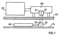
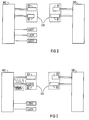
- FIG. 1 shows, in the structural application configuration and FIG. 2 in part in the associated block diagram, a bidirectional optical interface OS between an external programming and / or diagnostic unit DE above a radiation-permeable ceramic pane CE provided as a protective cover on the one hand and a control unit MC in the form of a microcontroller on the other hand, below the Ceran disc CE as part of an optoelectronic hotplate control arranged and connected on a PL board.
- a first transmitter S1 and a first receiver E1 are used on the top of the ceramic disc CE, and a second receiver E2 assigned to the first transmitter S1 and a second transmitter S2 assigned to the first receiver E1 are located below the ceramic disc CE .
- the second transmitter S2 and the second receiver E2 are connected to a serial interface output of the microcontroller, which a controller of this type, including the necessary test software, generally has.
- the signals of the mutual data exchange consist in particular of pulse-width-modulated pulse sequences which are transmitted without interference via the first transmitter S1 to the second receiver E2 by means of infrared radiation through the ceramic disc CE and lead to a specific command configuration in the microcontroller MC of the control unit; Corresponding feedback takes place via the second transmitter S2 by infrared radiation through the ceramic disc CE to the first receiver E1 and thus to the programming and / or diagnostic unit.
- an interface converter SW is provided on the external side between the first transmitter S1 and the first receiver E1, on the one hand, and the external programming and / or diagnostic unit DE, on the other hand, which converts the data from the programming and / or diagnostic unit DE Signals converted to so-called TTL levels.
- a total of three LED displays LED1-LED3 and a separate optical transmitter S1 or transmitter S2 are provided for each interface side in FIG.
- the outlay on components can advantageously be reduced by the fact that, according to the invention, an optically active display device, in the present case the first LED display device (LED1), is also used as a transmitter on the interface of the hob.
- an optically active display device in the present case the first LED display device (LED1)
- a high-frequency, in particular pulse-width-modulated, alternating signal f 1 is advantageously provided, or a low-frequency alternating signal f 2 or a direct signal is provided for the light activation of the LED display device LED1.
- an interface with a non-directional interface is of course also included in the invention if a display device which is provided per se is also used for the transmitter provided on one interface side and is fed with the interface signals.
Landscapes
- Physics & Mathematics (AREA)
- Electromagnetism (AREA)
- Engineering & Computer Science (AREA)
- Computer Networks & Wireless Communication (AREA)
- Signal Processing (AREA)
- Optical Communication System (AREA)
Applications Claiming Priority (2)
| Application Number | Priority Date | Filing Date | Title |
|---|---|---|---|
| DE19619927 | 1996-05-17 | ||
| DE1996119927 DE19619927C2 (de) | 1996-05-17 | 1996-05-17 | Optische Schnittstelle |
Publications (1)
| Publication Number | Publication Date |
|---|---|
| EP0808039A2 true EP0808039A2 (fr) | 1997-11-19 |
Family
ID=7794579
Family Applications (1)
| Application Number | Title | Priority Date | Filing Date |
|---|---|---|---|
| EP19970107311 Withdrawn EP0808039A2 (fr) | 1996-05-17 | 1997-05-02 | Interface optique |
Country Status (2)
| Country | Link |
|---|---|
| EP (1) | EP0808039A2 (fr) |
| DE (1) | DE19619927C2 (fr) |
Families Citing this family (3)
| Publication number | Priority date | Publication date | Assignee | Title |
|---|---|---|---|---|
| DE19802558A1 (de) * | 1998-01-23 | 1999-07-29 | Ego Elektro Geraetebau Gmbh | Steuerung für ein Elektrowärmegerät |
| DE102005010984A1 (de) * | 2005-03-03 | 2006-09-07 | E.G.O. Elektro-Gerätebau GmbH | Lüftungsgerät |
| DE102011008616A1 (de) * | 2011-01-14 | 2012-07-19 | Conti Temic Microelectronic Gmbh | Verfahren zur Datenübermittlung |
Family Cites Families (4)
| Publication number | Priority date | Publication date | Assignee | Title |
|---|---|---|---|---|
| DE3909126C2 (de) * | 1989-03-20 | 1998-06-04 | Diehl Gmbh & Co | Schaltgerät für einen Kochherd |
| DE3921344A1 (de) * | 1989-06-29 | 1991-01-10 | Hengstler Gmbh | Externes programmiergeraet |
| US5349162A (en) * | 1993-04-05 | 1994-09-20 | Whirlpool Corporation | Fault detection method and apparatus for a domestic appliance |
| DE19603295A1 (de) * | 1996-01-30 | 1997-07-31 | Siemens Ag | Optische Schnittstelle, insbesondere zur Diagnose einer optoelektronischen Kochstellensteuerung |
-
1996
- 1996-05-17 DE DE1996119927 patent/DE19619927C2/de not_active Expired - Lifetime
-
1997
- 1997-05-02 EP EP19970107311 patent/EP0808039A2/fr not_active Withdrawn
Also Published As
| Publication number | Publication date |
|---|---|
| DE19619927C2 (de) | 1998-06-04 |
| DE19619927A1 (de) | 1997-11-20 |
Similar Documents
| Publication | Publication Date | Title |
|---|---|---|
| EP0057892A3 (fr) | Partie de commande à fonction multiple | |
| DE102018119965A1 (de) | Verfahren zur automatischen Zuordnung mindestens eines Aufstellgeräts zu mindestens einer Kochstelle eines induktiven Kochfelds und System zur Durchführung des Verfahrens | |
| EP0811528B1 (fr) | Installation de commande | |
| EP0780081B2 (fr) | Méthode pour régler automatiquement des emplacements de cuisson chauffants | |
| EP0808039A2 (fr) | Interface optique | |
| EP2413667B1 (fr) | Dispositif de commande pour la commande d'une lampe et lampe | |
| EP0391090B1 (fr) | Liaison d'entraînement pour véhicule porteur d'outils | |
| DE102007018830A1 (de) | Anordnung zur Datenübertragung | |
| DE3437398A1 (de) | Elektroherd mit hochgelegtem bedienungspult | |
| EP0808038A2 (fr) | Dispositif d'affichage avec illumination d'affichage adaptée à la luminosité | |
| DE10156777B4 (de) | Verfahren zur Übertragung der Einstellungsdaten einer Kochstelle auf eine andere Kochstelle sowie Gargerät zur Durchführung dieses Verfahrens | |
| EP1876515A1 (fr) | Dispositif de commande | |
| DE19610073A1 (de) | Glaskeramikkochfeld | |
| EP0788250A2 (fr) | Interface optique pour diagnostiques d'une commande optoélectronique de points de cuisson | |
| WO2011076387A2 (fr) | Système d'installation électrique | |
| EP2258986A2 (fr) | Plaque de cuisson | |
| DE19743981A1 (de) | Verfahren zur Adressierung eines Aktuator-Sensor-Slaves sowie Aktuator-Sensor-Slave und Adressiergerät zur Durchführung des Verfahrens | |
| DE10359561B4 (de) | Bedienelement für ein Haushaltsgerät | |
| DE19546323C2 (de) | Mikrocontrollerschaltung für ein Haushaltsgerät | |
| DE19630992C1 (de) | Elektronische Steuereinheit, insbesondere Mikrocontroller | |
| DE4338082A1 (de) | Herd mit Kochfeld | |
| EP3780906B1 (fr) | Plaque de cuisson inductive, système comprenant une plaque de cuisson inductive et un appareil de montage et procédé de fonctionnement d'un système | |
| EP2398147B1 (fr) | Procédé et circuit électrique pour le fonctionnement d'un semi-conducteur de puissance électrique | |
| DE102019104011A1 (de) | Verfahren zur automatischen Zuordnung eines Aufstellgeräts zu einer Kochstelle eines induktiven Kochfelds, Aufstellgerät und System zur Durchführung des Verfahrens | |
| DE19625042B4 (de) | Steuer- bzw. Regelvorrichtung |
Legal Events
| Date | Code | Title | Description |
|---|---|---|---|
| PUAI | Public reference made under article 153(3) epc to a published international application that has entered the european phase |
Free format text: ORIGINAL CODE: 0009012 |
|
| AK | Designated contracting states |
Kind code of ref document: A2 Designated state(s): DE ES FR GB IT |
|
| STAA | Information on the status of an ep patent application or granted ep patent |
Free format text: STATUS: THE APPLICATION HAS BEEN WITHDRAWN |
|
| 18W | Application withdrawn |
Withdrawal date: 19990218 |