EP0808039A2 - Optical interface - Google Patents
Optical interface Download PDFInfo
- Publication number
- EP0808039A2 EP0808039A2 EP19970107311 EP97107311A EP0808039A2 EP 0808039 A2 EP0808039 A2 EP 0808039A2 EP 19970107311 EP19970107311 EP 19970107311 EP 97107311 A EP97107311 A EP 97107311A EP 0808039 A2 EP0808039 A2 EP 0808039A2
- Authority
- EP
- European Patent Office
- Prior art keywords
- optical interface
- transmitter
- electronic device
- receiver
- interface according
- Prior art date
- Legal status (The legal status is an assumption and is not a legal conclusion. Google has not performed a legal analysis and makes no representation as to the accuracy of the status listed.)
- Withdrawn
Links
- 230000003287 optical effect Effects 0.000 title claims abstract description 26
- 230000005540 biological transmission Effects 0.000 claims abstract description 9
- 230000005693 optoelectronics Effects 0.000 claims abstract description 4
- 230000002457 bidirectional effect Effects 0.000 claims description 4
- 230000004913 activation Effects 0.000 claims description 2
- 239000000919 ceramic Substances 0.000 description 6
- 238000010586 diagram Methods 0.000 description 3
- 230000005855 radiation Effects 0.000 description 2
- 230000008054 signal transmission Effects 0.000 description 2
- 230000006978 adaptation Effects 0.000 description 1
- 230000008878 coupling Effects 0.000 description 1
- 238000010168 coupling process Methods 0.000 description 1
- 238000005859 coupling reaction Methods 0.000 description 1
- 230000001419 dependent effect Effects 0.000 description 1
- 230000009977 dual effect Effects 0.000 description 1
- 238000000034 method Methods 0.000 description 1
- 238000001208 nuclear magnetic resonance pulse sequence Methods 0.000 description 1
- 238000004886 process control Methods 0.000 description 1
- 230000001681 protective effect Effects 0.000 description 1
Images
Classifications
-
- H—ELECTRICITY
- H04—ELECTRIC COMMUNICATION TECHNIQUE
- H04B—TRANSMISSION
- H04B10/00—Transmission systems employing electromagnetic waves other than radio-waves, e.g. infrared, visible or ultraviolet light, or employing corpuscular radiation, e.g. quantum communication
- H04B10/80—Optical aspects relating to the use of optical transmission for specific applications, not provided for in groups H04B10/03 - H04B10/70, e.g. optical power feeding or optical transmission through water
- H04B10/801—Optical aspects relating to the use of optical transmission for specific applications, not provided for in groups H04B10/03 - H04B10/70, e.g. optical power feeding or optical transmission through water using optical interconnects, e.g. light coupled isolators, circuit board interconnections
Definitions
- the invention relates to an optical interface.
- an external programming device for data input or output for programming systems for process control or the like is known, its coupling to the unit to be programmed as an optically working interface with mutually closed contact surfaces and mutually assignable light Transmitters or light sensors.
- the components and thus the costs are to be reduced in devices with an integrated optical interface and with an optically active display device, in particular in the form of an LED display or an LCD display.
- a display e.g. to display a setting or an operating mode
- existing optical active lights in particular in the form of an LED display or backlit LCD display, as a transmitter of the optical interface
- the display device used for the actual data transmission is expediently fed with a high-frequency, in particular pulse-width-modulated, alternating signal and for the illuminated display of a setting or operating mode with a low-frequency alternating signal or a direct signal.
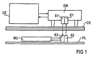
- FIG. 1 shows, in the structural application configuration and FIG. 2 in part in the associated block diagram, a bidirectional optical interface OS between an external programming and / or diagnostic unit DE above a radiation-permeable ceramic pane CE provided as a protective cover on the one hand and a control unit MC in the form of a microcontroller on the other hand, below the Ceran disc CE as part of an optoelectronic hotplate control arranged and connected on a PL board.
- a first transmitter S1 and a first receiver E1 are used on the top of the ceramic disc CE, and a second receiver E2 assigned to the first transmitter S1 and a second transmitter S2 assigned to the first receiver E1 are located below the ceramic disc CE .
- the second transmitter S2 and the second receiver E2 are connected to a serial interface output of the microcontroller, which a controller of this type, including the necessary test software, generally has.
- the signals of the mutual data exchange consist in particular of pulse-width-modulated pulse sequences which are transmitted without interference via the first transmitter S1 to the second receiver E2 by means of infrared radiation through the ceramic disc CE and lead to a specific command configuration in the microcontroller MC of the control unit; Corresponding feedback takes place via the second transmitter S2 by infrared radiation through the ceramic disc CE to the first receiver E1 and thus to the programming and / or diagnostic unit.
- an interface converter SW is provided on the external side between the first transmitter S1 and the first receiver E1, on the one hand, and the external programming and / or diagnostic unit DE, on the other hand, which converts the data from the programming and / or diagnostic unit DE Signals converted to so-called TTL levels.
- a total of three LED displays LED1-LED3 and a separate optical transmitter S1 or transmitter S2 are provided for each interface side in FIG.
- the outlay on components can advantageously be reduced by the fact that, according to the invention, an optically active display device, in the present case the first LED display device (LED1), is also used as a transmitter on the interface of the hob.
- an optically active display device in the present case the first LED display device (LED1)
- a high-frequency, in particular pulse-width-modulated, alternating signal f 1 is advantageously provided, or a low-frequency alternating signal f 2 or a direct signal is provided for the light activation of the LED display device LED1.
- an interface with a non-directional interface is of course also included in the invention if a display device which is provided per se is also used for the transmitter provided on one interface side and is fed with the interface signals.
Landscapes
- Physics & Mathematics (AREA)
- Electromagnetism (AREA)
- Engineering & Computer Science (AREA)
- Computer Networks & Wireless Communication (AREA)
- Signal Processing (AREA)
- Optical Communication System (AREA)
Abstract
Zur bauteilemindernden und damit kostengünstigen Ausführung einer optischen Schnittstelle mit optischer Datenübertragung zwischen je einem ersten Sender-Empfänger-Pärchen (S1;E1), insbesondere einer mobilen Programmier- und/oder Diagnoseeinrichtung (DE), und einem zweiten Sender-Empfänger-Pärchen (S2;E2), insbesondere einer optoelektronischen Kochstellensteuerung (MC) eines Herdes, ist für mindestens einen der beiden Sender (S1 bzw.S2) eine an sich vorhandene optische aktive Anzeigevorrichtung, insbesondere eine LED-Anzeigevorrichtung (LED1), mitbenutzt.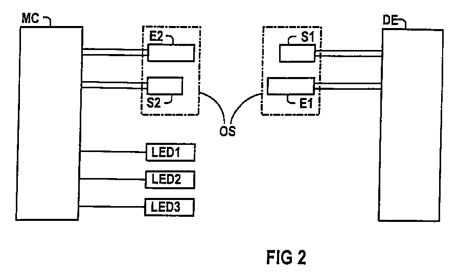

Description
Die Erfindung bezieht sich auf eine optische Schnittstelle, gemäß Patentanspruch 1.The invention relates to an optical interface.
Durch die DE-A1-39 21 344 ist ein externes Progammiergerät für eine Datenein- bzw. Datenausgabe zum Programmieren von Systemen zur Prozeßsteuerung oder dergleichen bekannt, dessen Ankopplung an die zu programmierende Einheit als optisch arbeitende Schittstelle mit beidseitig geschlossenen Berührungsflächen und gegenseitig einander zuordenbaren Licht-Sendern bzw. Licht-Sensoren ausgebildet ist.From DE-A1-39 21 344 an external programming device for data input or output for programming systems for process control or the like is known, its coupling to the unit to be programmed as an optically working interface with mutually closed contact surfaces and mutually assignable light Transmitters or light sensors.
Elektronische Einrichtungen, die Signale von durch optische Schnittstellen übertragenen Stellbefehlen verarbeiten, sind oftmals auch an Anzeigevorrichtungen in Form von optisch aktiven Leuchten, insbesondere selbstleuchtenden LED-Anzeigen bzw. hintergrundbeleuchteten LCD-Anzeigen, angeschlossen, die diese Stellbefehle anzeigen. So wird in der DE 39 09 126 A1 ein Schaltgerät für einen Kochherd mit einer Infrarot- oder Ultraschallsignalübertragung zwischen einer Bedieneinheit in einer Dunstabzugshaube über dem Kochherd einerseits und einem Leistungsschaltteil in dem Kochherd andererseits beschrieben, wobei die Bedieneinheit eine zusätzliche Kontrolleinrichtung zur Anzeige einer Unterbrechung der Signalübertragung und/oder zur Anzeige der tatsachlich eingeschalteten Kochfelder aufweist.Electronic devices that process signals from control commands transmitted through optical interfaces are often also connected to display devices in the form of optically active lights, in particular self-illuminating LED displays or backlit LCD displays, which display these control commands. DE 39 09 126 A1 describes a switching device for a cooker with an infrared or ultrasonic signal transmission between an operating unit in an extractor hood above the cooker on the one hand and a power switching part in the cooker on the other hand, the control unit providing an additional control device for indicating an interruption of the Signal transmission and / or to display the hobs actually switched on.
In der deutschen Patentanmeldung mit dem amtlichen Aktenzeichen 196 03 295.4 ist bereits eine optoelektronische Kochstellensteuerung mit einer optischen Schnittstelle vorgeschlagen worden, über die eine Programmier- und/oder eine Diagnoseeinheit mit einer Kochstellensteuerung ohne Notwendigkeit einer elektrischen Leitungs- bzw. Steckereinrichtung Daten austauschen kann.In the German patent application with the official file number 196 03 295.4, an optoelectronic hotplate controller with an optical interface has already been proposed, via which a programming and / or a diagnostic unit can exchange data with a hotplate controller without the need for an electrical line or plug device.
Gemäß Aufgabe vorliegender Erfindung soll bei Vorrichtungen mit integrierter optischer Schnittstelle und mit optisch aktiver Anzeigevorrichtung, insbesondere in Form einer LED-Anzeige bzw. einer LCD-Anzeige, der Bauteile- und damit Kostenaufwand gemindert werden.According to the object of the present invention, the components and thus the costs are to be reduced in devices with an integrated optical interface and with an optically active display device, in particular in the form of an LED display or an LCD display.
Die Lösung dieser Aufgabe gelingt durch eine optische Schnittstelle gemäß Patentanspruch 1; vorteilhafte Ausgestaltungen der Erfindung sind jeweils Gegenstand der Unteransprüche.This object is achieved by an optical interface according to
Durch die erfindungsgemäße Mitbenutzung einer an sich zur Anzeige, z.B. zur Anzeige einer Einstellung oder einer Betriebsart, vorhandenen optischen aktiven Leuchten, insbesondere in Form einer LED-Anzeige bzw. hintergrundbeleuchteten LCD-Anzeige, als Sender der optischen Schnittstelle kann deren Bauteileaufwand in vorteilhafter Weise gemindert werden; zweckmäßigerweise ist die mitbenutzte Anzeigevorrichtung für die eigentliche Datenübertragung mit einem hochfrequenten, insbesondere pulsweitenmodulierten, Wechselsignal und für die beleuchtete Anzeige einer Einstellung bzw. Betriebsart mit einem niederfrequenten Wechselsignal bzw. einem Gleichsignal gespeist.Due to the shared use of a display, e.g. to display a setting or an operating mode, existing optical active lights, in particular in the form of an LED display or backlit LCD display, as a transmitter of the optical interface, the amount of components involved can be advantageously reduced; The display device used for the actual data transmission is expediently fed with a high-frequency, in particular pulse-width-modulated, alternating signal and for the illuminated display of a setting or operating mode with a low-frequency alternating signal or a direct signal.
Die Erfindung sowie weitere vorteilhafte Ausgestaltungen der Erfindung gemäß Merkmalen der Unteransprüche werden im folgenden anhand eines schematisch dargestellten Ausführungsbeispiels in der Zeichnung näher erläutert; darin zeigen:
- FIG 1
- Eine optische Schnittstelle mit auf eine Ceran-Abdeckscheibe einer Kochstellensteuerung aufgesetzter externer Programmier- und/oder Diagnoseeinheit;
- FIG 2
- das Blockschaltbild einer optischen Schnittstelle gemaß FIG 1 mit gleichzeitig deren einem Teil zugeordneten Anzeigevorrichtungen;
- FIG 3
- das Blockschaltbild gemaß FIG 2 mit erfindungsgemäßer Doppelnutzung einer Anzeigevorrichtung.
- FIG. 1
- An optical interface with an external programming and / or diagnostic unit placed on a ceramic cover plate of a hotplate controller;
- FIG 2
- the block diagram of an optical interface according to FIG 1 with their display devices assigned to a part at the same time;
- FIG 3
- the block diagram of FIG 2 with dual use of a display device according to the invention.
FIG 1 zeigt in der baulichen Anwendungsfiguration und FIG 2 ausschnittsweise im zugehörigen Blockschaltbild eine bidirektionale optische Schnittstelle OS zwischen einer externen Programmier- und/oder Diagnoseeinheit DE oberhalb einer als Schutzabdeckung vorgesehenen strahlungsdurchlässigen Ceran-Scheibe CE einerseits und einer Steuereinheit MC in Form eines Mikro-Controllers unterhalb der Ceran-Scheibe CE als Bestandteil einer auf einer Platine PL angeordneten und verschalteten optoelektronischen Kochstellensteuerung andererseits. Zur bidirektionalen optischen Datenübertragung der Schnittstelle dienen auf der Oberseite der Ceran-Scheibe CE ein erster Sender S1 sowie ein erster Empfänger E1 sowie unterhalb der Ceran-Scheibe CE ein dem ersten Sender S1 zugeordneter zweiter Empfänger E2 und ein dem ersten Empfänger E1 zugeordneter zweiter Sender S2. Der zweite Sender S2 und der zweite Empfänger E2 sind an einen seriellen Schnittstellenausgang des Mikro-Controllers angeschlossen, über den ein derartiger Controller einschließlich der notwendigen Prüfsoftware in der Regel verfügt.1 shows, in the structural application configuration and FIG. 2 in part in the associated block diagram, a bidirectional optical interface OS between an external programming and / or diagnostic unit DE above a radiation-permeable ceramic pane CE provided as a protective cover on the one hand and a control unit MC in the form of a microcontroller on the other hand, below the Ceran disc CE as part of an optoelectronic hotplate control arranged and connected on a PL board. For bidirectional optical data transmission of the interface, a first transmitter S1 and a first receiver E1 are used on the top of the ceramic disc CE, and a second receiver E2 assigned to the first transmitter S1 and a second transmitter S2 assigned to the first receiver E1 are located below the ceramic disc CE . The second transmitter S2 and the second receiver E2 are connected to a serial interface output of the microcontroller, which a controller of this type, including the necessary test software, generally has.
Die Signale des gegenseitigen Datenaustausches bestehen insbesondere aus spezifisch pulsweitenmodulierten Pulsfolgen, die über den ersten Sender S1 störungsfrei an den zweiten Empfänger E2 mittels Infrarotstrahlung durch die Ceran-Scheibe CE übertragen werden und zu einer bestimmten Befehlskonstellation im Mikro-Controller MC der Steuereinheit führen; entsprechende Rückmeldungen erfolgen über den zweiten Sender S2 durch Infrarotstrahlung durch die Ceran-Scheibe CE an den ersten Empfänger E1 und somit an die Programmier- und/oder Diagnoseeinheit.The signals of the mutual data exchange consist in particular of pulse-width-modulated pulse sequences which are transmitted without interference via the first transmitter S1 to the second receiver E2 by means of infrared radiation through the ceramic disc CE and lead to a specific command configuration in the microcontroller MC of the control unit; Corresponding feedback takes place via the second transmitter S2 by infrared radiation through the ceramic disc CE to the first receiver E1 and thus to the programming and / or diagnostic unit.
Zur normierten Anpassung ist auf der externen Seite zwischen dem ersten Sender S1 und dem ersten Empfänger E1 einerseits sowie der externen Programmier- und/oder Diagnoseeinheit DE andererseits ein Schnittstellenwandler SW vorgesehen, der die von der Programmier- und oder Diagnoseeinheit DE aus- bzw. eingehenden Signale auf sogenannten TTL-Pegel konvertiert.For standardized adaptation, an interface converter SW is provided on the external side between the first transmitter S1 and the first receiver E1, on the one hand, and the external programming and / or diagnostic unit DE, on the other hand, which converts the data from the programming and / or diagnostic unit DE Signals converted to so-called TTL levels.
Entsprechend unterschiedlichen Einstellungen werden in einer Bedienfront über direkt leuchtende LED-Anzeigen LED1-LED3 beleuchtete Einstellanzeigen einer Kochstellensteuerung oder durch hintergrundbeleuchtete LCD-Anzeigen Betriebsartenanzeigen einer Backofensteuerung aktiviert.Corresponding to different settings, illuminated setting displays of a hotplate control or activated by backlit LCD displays, operating mode displays of an oven control, are activated in a control front via directly illuminated LED displays LED1-LED3.
In FIG 2 sind insgesamt drei LED-Anzeigen LED1-LED3 und jeweils ein gesonderter optischer Sender S1 bzw. Sender S2 für jede Schnittstellenseite vorgesehen.A total of three LED displays LED1-LED3 and a separate optical transmitter S1 or transmitter S2 are provided for each interface side in FIG.
Gemäß FIG 3 kann der Bauteileaufwand dadurch in vorteilhafter Weise gemindert werden, daß erfindungsgemäß eine an sich vorhandene optisch aktive Anzeigevorrichtung, im vorliegenden Fall die erste LED-Anzeigevorrichtung (LED1), als kochstellenseitiger Sender der Schnittstelle mitbenutzt ist.According to FIG. 3, the outlay on components can advantageously be reduced by the fact that, according to the invention, an optically active display device, in the present case the first LED display device (LED1), is also used as a transmitter on the interface of the hob.
Für den eigentlichen Datenaustausch der Schnittstelle ist in vorteilhafter Weise ein hochfrequentes, insbesondere jeweils spezifisch pulsweitenmoduliertes, Wechselsignal f1 bzw. für die Leuchtaktivierung der LED-Anzeigevorrichtung LED1 ein niederfrequentes Wechselsignal f2 oder ein Gleichsignal vorgesehen.For the actual data exchange of the interface, a high-frequency, in particular pulse-width-modulated, alternating signal f 1 is advantageously provided, or a low-frequency alternating signal f 2 or a direct signal is provided for the light activation of the LED display device LED1.
Obwohl die Erfindung anhand einer Schnittstelle mit bidirektionaler Datenübertragung beschrieben wurde, ist selbstverständlich auch eine Schnittstelle mit undirektionaler Schnittstelle von der Erfindung mitumfaßt, wenn für den dann nur auf einer Schnittstellenseite vorgesehenen Sender eine an sich vorhandene Anzeigevorrichtung mitbenutzt und mit den Schnittstellen-Signalen gespeist ist.Although the invention has been described on the basis of an interface with bidirectional data transmission, an interface with a non-directional interface is of course also included in the invention if a display device which is provided per se is also used for the transmitter provided on one interface side and is fed with the interface signals.
Claims (8)
Applications Claiming Priority (2)
| Application Number | Priority Date | Filing Date | Title |
|---|---|---|---|
| DE19619927 | 1996-05-17 | ||
| DE1996119927 DE19619927C2 (en) | 1996-05-17 | 1996-05-17 | Optical interface |
Publications (1)
| Publication Number | Publication Date |
|---|---|
| EP0808039A2 true EP0808039A2 (en) | 1997-11-19 |
Family
ID=7794579
Family Applications (1)
| Application Number | Title | Priority Date | Filing Date |
|---|---|---|---|
| EP19970107311 Withdrawn EP0808039A2 (en) | 1996-05-17 | 1997-05-02 | Optical interface |
Country Status (2)
| Country | Link |
|---|---|
| EP (1) | EP0808039A2 (en) |
| DE (1) | DE19619927C2 (en) |
Families Citing this family (3)
| Publication number | Priority date | Publication date | Assignee | Title |
|---|---|---|---|---|
| DE19802558A1 (en) * | 1998-01-23 | 1999-07-29 | Ego Elektro Geraetebau Gmbh | Control for heating device for e.g. electric cooking hob |
| DE102005010984A1 (en) * | 2005-03-03 | 2006-09-07 | E.G.O. Elektro-Gerätebau GmbH | Ventilation unit |
| DE102011008616A1 (en) * | 2011-01-14 | 2012-07-19 | Conti Temic Microelectronic Gmbh | Method for data transmission |
Family Cites Families (4)
| Publication number | Priority date | Publication date | Assignee | Title |
|---|---|---|---|---|
| DE3909126C2 (en) * | 1989-03-20 | 1998-06-04 | Diehl Gmbh & Co | Switchgear for a cooker |
| DE3921344A1 (en) * | 1989-06-29 | 1991-01-10 | Hengstler Gmbh | External data programming unit - has magnetically latched cable coupling providing communication with programmable controller |
| US5349162A (en) * | 1993-04-05 | 1994-09-20 | Whirlpool Corporation | Fault detection method and apparatus for a domestic appliance |
| DE19603295A1 (en) * | 1996-01-30 | 1997-07-31 | Siemens Ag | Optical interface, in particular for diagnosis of an optoelectronic hotplate control |
-
1996
- 1996-05-17 DE DE1996119927 patent/DE19619927C2/en not_active Expired - Lifetime
-
1997
- 1997-05-02 EP EP19970107311 patent/EP0808039A2/en not_active Withdrawn
Also Published As
| Publication number | Publication date |
|---|---|
| DE19619927C2 (en) | 1998-06-04 |
| DE19619927A1 (en) | 1997-11-20 |
Similar Documents
| Publication | Publication Date | Title |
|---|---|---|
| EP0057892A3 (en) | Multi-function control part | |
| DE102018119965A1 (en) | Method for automatically assigning at least one set-up device to at least one hotplate of an inductive hob and system for carrying out the method | |
| EP0811528B1 (en) | Control installation | |
| EP0780081B2 (en) | Method for the automatic regulation of heatable cooking surfaces | |
| EP0808039A2 (en) | Optical interface | |
| EP2413667B1 (en) | Control device for controlling a light and light | |
| EP0391090B1 (en) | Drive connection for a vehicle with mounted implements | |
| DE102007018830A1 (en) | Arrangement for data transmission | |
| DE3437398A1 (en) | Electric cooker having a high-level control panel | |
| EP0808038A2 (en) | Display device with brightness-adapted display illumination | |
| DE10156777B4 (en) | Method for transferring the setting data of a cooking area to another cooking area and cooking appliance for carrying out this method | |
| EP1876515A1 (en) | Operating device | |
| DE19610073A1 (en) | Ceramic glass cooking hob | |
| EP0788250A2 (en) | Optical interface for the diagnosis of optoelectronic cooking appliance control | |
| WO2011076387A2 (en) | Electrical installation system | |
| EP2258986A2 (en) | Hot plate | |
| DE19743981A1 (en) | Method for addressing an actuator-sensor slave as well as actuator-sensor slave and addressing device for performing the method | |
| DE10359561B4 (en) | Operating element for a household appliance | |
| DE19546323C2 (en) | Microcontroller circuit for a household appliance | |
| DE19630992C1 (en) | Electronic control unit esp. micro-controller | |
| DE4338082A1 (en) | Stove with hob | |
| EP3780906B1 (en) | Inductive hob, system comprising an inductive hob and a setting device, and method for operating a system | |
| EP2398147B1 (en) | Method and electrical switch for operating an electrical power semiconductor element | |
| DE102019104011A1 (en) | Method for the automatic assignment of an installation device to a hotplate of an inductive hob, installation device and system for carrying out the method | |
| DE19625042B4 (en) | Control device |
Legal Events
| Date | Code | Title | Description |
|---|---|---|---|
| PUAI | Public reference made under article 153(3) epc to a published international application that has entered the european phase |
Free format text: ORIGINAL CODE: 0009012 |
|
| AK | Designated contracting states |
Kind code of ref document: A2 Designated state(s): DE ES FR GB IT |
|
| STAA | Information on the status of an ep patent application or granted ep patent |
Free format text: STATUS: THE APPLICATION HAS BEEN WITHDRAWN |
|
| 18W | Application withdrawn |
Withdrawal date: 19990218 |