EP0788250A2 - Optical interface for the diagnosis of optoelectronic cooking appliance control - Google Patents
Optical interface for the diagnosis of optoelectronic cooking appliance control Download PDFInfo
- Publication number
- EP0788250A2 EP0788250A2 EP97100681A EP97100681A EP0788250A2 EP 0788250 A2 EP0788250 A2 EP 0788250A2 EP 97100681 A EP97100681 A EP 97100681A EP 97100681 A EP97100681 A EP 97100681A EP 0788250 A2 EP0788250 A2 EP 0788250A2
- Authority
- EP
- European Patent Office
- Prior art keywords
- receiver
- transmitter
- optical interface
- feature
- interface
- Prior art date
- Legal status (The legal status is an assumption and is not a legal conclusion. Google has not performed a legal analysis and makes no representation as to the accuracy of the status listed.)
- Withdrawn
Links
- 230000003287 optical effect Effects 0.000 title claims abstract description 19
- 230000005693 optoelectronics Effects 0.000 title claims description 6
- 238000003745 diagnosis Methods 0.000 title abstract 2
- 238000010411 cooking Methods 0.000 title 1
- 230000005540 biological transmission Effects 0.000 claims abstract description 12
- 239000000919 ceramic Substances 0.000 claims description 9
- 230000001681 protective effect Effects 0.000 claims description 5
- 230000002457 bidirectional effect Effects 0.000 claims 1
- 230000008878 coupling Effects 0.000 description 2
- 238000010168 coupling process Methods 0.000 description 2
- 238000005859 coupling reaction Methods 0.000 description 2
- 238000010586 diagram Methods 0.000 description 2
- 230000005855 radiation Effects 0.000 description 2
- 230000006978 adaptation Effects 0.000 description 1
- 238000004519 manufacturing process Methods 0.000 description 1
- 238000004886 process control Methods 0.000 description 1
Images

Classifications
-
- G—PHYSICS
- G08—SIGNALLING
- G08C—TRANSMISSION SYSTEMS FOR MEASURED VALUES, CONTROL OR SIMILAR SIGNALS
- G08C23/00—Non-electrical signal transmission systems, e.g. optical systems
- G08C23/04—Non-electrical signal transmission systems, e.g. optical systems using light waves, e.g. infrared
-
- H—ELECTRICITY
- H05—ELECTRIC TECHNIQUES NOT OTHERWISE PROVIDED FOR
- H05B—ELECTRIC HEATING; ELECTRIC LIGHT SOURCES NOT OTHERWISE PROVIDED FOR; CIRCUIT ARRANGEMENTS FOR ELECTRIC LIGHT SOURCES, IN GENERAL
- H05B3/00—Ohmic-resistance heating
- H05B3/68—Heating arrangements specially adapted for cooking plates or analogous hot-plates
- H05B3/74—Non-metallic plates, e.g. vitroceramic, ceramic or glassceramic hobs, also including power or control circuits
-
- G—PHYSICS
- G08—SIGNALLING
- G08C—TRANSMISSION SYSTEMS FOR MEASURED VALUES, CONTROL OR SIMILAR SIGNALS
- G08C2201/00—Transmission systems of control signals via wireless link
- G08C2201/20—Binding and programming of remote control devices
- G08C2201/21—Programming remote control devices via third means
-
- G—PHYSICS
- G08—SIGNALLING
- G08C—TRANSMISSION SYSTEMS FOR MEASURED VALUES, CONTROL OR SIMILAR SIGNALS
- G08C2201/00—Transmission systems of control signals via wireless link
- G08C2201/50—Receiving or transmitting feedback, e.g. replies, status updates, acknowledgements, from the controlled devices
Definitions
- the invention relates to an optical interface, in particular for diagnosing an optoelectronic hotplate control, according to claim 1.
- an external programming device for data input or output for programming systems for process control or the like is known, its coupling to the unit to be programmed as an optically working interface with mutually closed contact surfaces and mutually assignable light Transmitters or light sensors.
- such an optical interface in particular when applied to an external programming and / or diagnostic unit for an optical hotplate controller covered by a protective pane, is to be upgraded with a view to high insensitivity to external or stray influences.
- the coupling according to the invention between a programming and / or diagnostic unit on the one hand and a control unit on the other hand ensures a high transmission quality of the transmitted pulse-width-modulated signals, despite the fact that a mutual galvanic connection is advantageous for simple handling, since the high steepness of the edge means that it is conventional and has no steep edges Ambient light and the high pulse amplitude of transmission pulses from conventional remote controls that are usually not in the immediate vicinity have no influence.
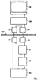
- FIG. 1 shows in the structural application configuration and FIG. 3 in the associated block diagram shows an optical interface between an external programming and / or diagnostic unit DE above a radiation-permeable ceramic pane CE provided as a protective cover and a control unit MC in the form of a microcontroller below the ceramic pane.
- Disc CE as a component of an optoelectronic hotplate control arranged and connected on a circuit board (PL) with a plurality of optoelectronic touch keys (not shown here).
- a first transmitter S1 and a first receiver E1 are used for optical transmission on the upper side of the ceramic disc CE and a second receiver E2 assigned to the first transmitter S1 and a second transmitter S2 assigned to the first receiver E1 are located below the ceramic disc CE.
- the second transmitter S2 and the second receiver E2 are connected to a serial interface output of the microcontroller, which a controller of this type, including the necessary test software, generally has.
- the latter advantageously remains blocked during the transmission time of the activated transmitter; the data are transmitted in half-duplex mode, in which only one of the participants alternately transmits, while the other participant only receives.
- an interface converter SW is provided on the external side between the first transmitter S1 and the first receiver E1, on the one hand, and the external programming and / or diagnostic unit DE, on the other hand, which converts or outputs the programming and / or diagnostic unit DE. incoming signals converted to the so-called TTL level.
- this microcontroller itself can be used as a diagnostic component, in particular during the production process, in order to be able to check the correct functioning of the entire hotplate control; In addition, an initialization or update of operating parameters and, if necessary, customer service can be quickly localized, the errors are possible.
- FIG. 2 shows in its upper first picture the example of a pulse train for a pulse-width-modulated signal which can be transmitted without interference via the first transmitter S1 to the second receiver E2 by means of infrared radiation through the ceramic disc CE and for a specific command configuration in the microcontroller MC the control unit, which in turn can then provide feedback via the second transmitter S2 by infrared radiation through the ceramic disc CE to the first receiver E1 and thus to the programming and / or diagnostic unit.
- the output signals are usually set to high, the data bits to active low.
- an infrared LED provided as the first transmitter S1 is pulsed, whereby no current flows during the transmission pole breaks, but a short current surge is generated during the respective pulse-compliant switch-on in such a way that the necessary high slope and high pulse amplitude is achieved;
- the infrared signal formed in this way is shown with a steep flank during the respective pulse change in accordance with the first signal curve.
- the corresponding signal arriving below the ceramic disc CE at the second receiver E2 is made up of the signal emitted by the first transmitter S1 with increased edge steepness and pulse amplitude and a superimposed noise caused by disturbance variables such as e.g. Room lighting and remote controls together.
- This signal is the input signal of a differentiator DI downstream of the second receiver E2, the output signal of which is a function of the steepness of its input signals.
- a signal change corresponding to the processed pulse edges of the signal curve in the first image leads to a short output pulse with a high amplitude, while a slow signal change only leads to a small output amplitude. This last state of affairs is indicated in the waveform of the fourth image in FIG. 2.
- the differentiator DE is assigned a Schmitt trigger ST with an upper and a lower switching threshold, indicated with a dashed curve in the fourth image, by means of which the original pulse-width-modulated signal according to the signal curve in the fifth image can be back-modulated that a pulse edge is set by a large output amplitude each time a switching threshold is reached.
Abstract
Description
Die Erfindung bezieht sich auf eine optische Schnittstelle, insbesondere zur Diagnose einer optoelektronischen Kochstellensteuerung, gemäß Patentanspruch 1.The invention relates to an optical interface, in particular for diagnosing an optoelectronic hotplate control, according to
Durch die DE-A1-39 21 344 ist ein externes Progammiergerät für eine Datenein- bzw. Datenausgabe zum Programmieren von Systemen zur Prozeßsteuerung oder dergleichen bekannt, dessen Ankopplung an die zu programmierende Einheit als optisch arbeitende Schittstelle mit beidseitig geschlossenen Berührungsflächen und gegenseitig einander zuordenbaren Licht-Sendern bzw. Licht-Sensoren ausgebildet ist.From DE-A1-39 21 344 an external programming device for data input or output for programming systems for process control or the like is known, its coupling to the unit to be programmed as an optically working interface with mutually closed contact surfaces and mutually assignable light Transmitters or light sensors.
Gemäß Aufgabe vorliegender Erfindung soll eine derartige optische Schnittstelle, insbesondere in Anwendung auf eine externe Programmier- und/oder Diagnoseeinheit für eine durch eine Schutzscheibe abgedeckte optische Kochstellensteuerung, im Hinblick auf hohe Unempfindlichkeit gegenüber Fremd- bzw. Streulicheinflüsse ertüchtigt werden.According to the object of the present invention, such an optical interface, in particular when applied to an external programming and / or diagnostic unit for an optical hotplate controller covered by a protective pane, is to be upgraded with a view to high insensitivity to external or stray influences.
Die erfindungsgemäße Ankopplung zwischen einer Programmier- und/oder Diagnoseeinheit einerseits und einer Steuereinheit andererseits gewährleistet trotz des für eine einfache Handhabung vorteilhaften Verzichts auf eine gegenseitige galvanische Verbindung eine hohe Übertragungsgüte der gesendeten pulsweitenmodulierten Signale, da durch die hohe Flankensteilheit ein herkömmliches, keine steilen Flanken aufweisendes Raumlicht und durch die hohe Pulsamplitude Sendeimpulse von üblicherweise nicht in unmittelbarer Nähe befindlichen üblichen Fernbedienungen ohne Einfluß bleiben.The coupling according to the invention between a programming and / or diagnostic unit on the one hand and a control unit on the other hand ensures a high transmission quality of the transmitted pulse-width-modulated signals, despite the fact that a mutual galvanic connection is advantageous for simple handling, since the high steepness of the edge means that it is conventional and has no steep edges Ambient light and the high pulse amplitude of transmission pulses from conventional remote controls that are usually not in the immediate vicinity have no influence.
Die Erfindung sowie weitere vorteilhafte Ausgestaltungen der Erfindung gemäß Merkmalen der Unteransprüche werden im folgenden anhand schematisch dargestellter Ausführungsbeispiele in der Zeichnung näher erläutert; darin zeigen:
- FIG 1
- Eine optische Schnittstelle mit auf eine Ceran-Abdeckscheibe einer Kochstellensteuerung aufgesetzter externer Programmier- und/oder Diagnoseeinheit;
- FIG 2
- ausgehend von einem durch die Programmier- und/oder Diagnoseeinheit abgegebenen pulsweitenmodulierten Diagnosesignal dessen erfindungsgemäße Bearbeitung zur Erzielung einer hohen Übertragungsgüte;
- FIG 3
- das Blockschaltbild zu der in FIG 1 in seiner Anwendungsfiguration dargestellten optischen Schnittstelle.
- FIG. 1
- An optical interface with an external programming and / or diagnostic unit placed on a ceramic cover plate of a hotplate controller;
- FIG 2
- on the basis of a pulse-width-modulated diagnostic signal emitted by the programming and / or diagnostic unit, the processing according to the invention for achieving a high transmission quality;
- FIG 3
- the block diagram of the optical interface shown in FIG 1 in its application configuration.
FIG 1 zeigt in der baulichen Anwendungsfiguration und FIG 3 im zugehörigen Blockschaltbild eine optische Schnittstelle zwischen einer externen Programmier- und/oder Diagnoseeinheit DE oberhalb einer als Schutzabdeckung vorgesehenen strahlungsdurchlässigen Ceran-Scheibe CE und einer Steuereinheit MC in Form eines Mikro-Controllers unterhalb der Ceran-Scheibe CE als Bestandteil einer auf einer Platine (PL) angeordneten und verschalteten optoelektronischen Kochstellensteuerung mit hier nicht näher dargestellten mehreren optoelektronischen Berührungstasten. Zur optischen Übertragung dienen auf der Oberseite der Ceran-Scheibe CE ein erster Sender S1 sowie ein erster Empfänger E1 sowie unterhalb der Ceran-Scheibe CE ein dem ersten Sender S1 zugeordneter zweiter Empfänger E2 und ein dem ersten Empfänger E1 zugeordneter zweiter Sender S2. Der zweite Sender S2 und der zweite Empfänger E2 sind an einen seriellen Schnittstellenausgang des Mikro-Controllers angeschlossen, über den ein derartiger Controller einschließlich der notwendigen Prüfsoftware in der Regel verfügt.1 shows in the structural application configuration and FIG. 3 in the associated block diagram shows an optical interface between an external programming and / or diagnostic unit DE above a radiation-permeable ceramic pane CE provided as a protective cover and a control unit MC in the form of a microcontroller below the ceramic pane. Disc CE as a component of an optoelectronic hotplate control arranged and connected on a circuit board (PL) with a plurality of optoelectronic touch keys (not shown here). A first transmitter S1 and a first receiver E1 are used for optical transmission on the upper side of the ceramic disc CE and a second receiver E2 assigned to the first transmitter S1 and a second transmitter S2 assigned to the first receiver E1 are located below the ceramic disc CE. The second transmitter S2 and the second receiver E2 are connected to a serial interface output of the microcontroller, which a controller of this type, including the necessary test software, generally has.
Um einen Störeinfluß, insbesondere durch unmittelbare Reflexion an der Schutzabdeckung, eines aktivierten Senders auf seinen zugehörigen, in der gleichen Sende- bzw. Empfangsebene benachbarten Empfänger auszuschließen, bleibt dieser in vorteilhafter Weise wahrend der Sendezeit des aktivierten Senders gesperrt; die Daten werden im Halbduplexverfahren übertragen, bei dem abwechselnd nur einer der Teilnehmer sendet, wahrend der andere Teilnehmer nur empfängt.In order to prevent interference, in particular due to direct reflection on the protective cover, of an activated transmitter on its associated receiver, which is adjacent in the same transmission or reception level, the latter advantageously remains blocked during the transmission time of the activated transmitter; the data are transmitted in half-duplex mode, in which only one of the participants alternately transmits, while the other participant only receives.
Zur normierten Anpassung ist auf der externen Seite zwischen dem ersten Sender S1 und dem ersten Empfänger E1 einerseits sowie der externen Programmier- und/oder Diagnoseeinheit DE andererseits ein Schnittstellenwandler SW vorgesehen, der die von der Programmier- und/oder Diagnoseeinheit DE aus- bzw. eingehenden Signale auf sogenannten TTL-Pegel konvertiert.For standardized adaptation, an interface converter SW is provided on the external side between the first transmitter S1 and the first receiver E1, on the one hand, and the external programming and / or diagnostic unit DE, on the other hand, which converts or outputs the programming and / or diagnostic unit DE. incoming signals converted to the so-called TTL level.
Durch die Einbeziehung des an sich für die Kochstellensteuerung vorgesehenen Mikro-Controllers kann, insbesondere während des Fertigungsablaufs, dieser Mikro-Controller selbst als diagnostizierendes Bauteil mitverwendet werden, um die korrekte Funktion der gesamten Kochstellensteuerung prüfen zu können; darüber hinaus ist auf einfache Weise eine Initialisierung bzw. Aktualisierung von Betriebsparametern und bei einem eventuell notwendigen Kundendiensteinsatz eine schnelle Lokalisierung der Fehler möglich.Through the inclusion of the microcontroller provided per se for the hotplate control, this microcontroller itself can be used as a diagnostic component, in particular during the production process, in order to be able to check the correct functioning of the entire hotplate control; In addition, an initialization or update of operating parameters and, if necessary, customer service can be quickly localized, the errors are possible.
FIG 2 zeigt in seinem oberen ersten Bild das Beispiel einer Pulsfolge für ein pulsweitenmoduliertes Signal, das über den ersten Sender S1 störungsfrei an den zweiten Empfänger E2 mittels Infrarotstrahlung durch die Ceran-Scheibe CE zu übertragen ist und zu einer bestimmten Befehlskonstellation im Mikro-Controller MC der Steuereinheit führen soll, die seinerseits dann eine Rückmeldung über den zweiten Sender S2 durch Infrarotstrahlung durch die Ceran-Scheibe CE an den ersten Empfänger E1 und somit an die Programmier- und/oder Diagnoseeinheit geben kann. Die Ausgangssignale sind dabei normalerweise auf High, die Datenbits auf aktiv Low gesetzt.2 shows in its upper first picture the example of a pulse train for a pulse-width-modulated signal which can be transmitted without interference via the first transmitter S1 to the second receiver E2 by means of infrared radiation through the ceramic disc CE and for a specific command configuration in the microcontroller MC the control unit, which in turn can then provide feedback via the second transmitter S2 by infrared radiation through the ceramic disc CE to the first receiver E1 and thus to the programming and / or diagnostic unit. The output signals are usually set to high, the data bits to active low.
Entsprechend den Pulsen des Signalverlaufes im ersten Bild in FIG 2 wird eine als erster Sender S1 vorgesehene Infrarot-LED gepulst, wobei in dieser während der Übertragungspolpausen kein Strom fließt, jedoch beim jeweiligen pulskonformen Einschalten ein kurzer Stromstoß derart erzeugt wird, daß die notwendige hohe Flankensteilheit und hohe Pulsamplitude erreicht wird; im zweiten Signalverlauf von FIG 2 ist das derart gebildete ausgesendete Infrarotsignal mit steiler Flanke beim jeweiligen Pulswechsel gemäß dem ersten Signalverlauf dargestellt. Das entsprechende unterhalb der Ceran-Scheibe CE am zweiten Empfänger E2 ankommende Signal setzt sich gemäß dem dritten Signalverlauf in FIG 2 aus dem vom ersten Sender S1 abgestrahlten Signal mit erhöhter Flankensteilheit und Pulsamplitude und einem überlagerten Rauschen durch Störgrößen wie z.B. Raumbeleuchtung und Fernbedienungen zusammen.Corresponding to the pulses of the signal curve in the first picture in FIG. 2, an infrared LED provided as the first transmitter S1 is pulsed, whereby no current flows during the transmission pole breaks, but a short current surge is generated during the respective pulse-compliant switch-on in such a way that the necessary high slope and high pulse amplitude is achieved; In the second signal curve of FIG. 2, the infrared signal formed in this way is shown with a steep flank during the respective pulse change in accordance with the first signal curve. According to the third signal curve in FIG. 2, the corresponding signal arriving below the ceramic disc CE at the second receiver E2 is made up of the signal emitted by the first transmitter S1 with increased edge steepness and pulse amplitude and a superimposed noise caused by disturbance variables such as e.g. Room lighting and remote controls together.
Dieses Signal ist Eingangssignal eines nach einer Ausgestaltung der Erfindung dem zweiten Empfänger E2 nachgeschalteten Differenzierers DI, dessen Ausgangssignal eine Funktion der Steilheit seiner Eingangssignale ist. Eine Signaländerung entsprechend den bearbeiteten Pulsflanken des Signalverlaufs im ersten Bild führt zu einem kurzen Ausgangsimpuls mit hoher Amplitude, während eine langsame Signaländerung nur zu einer kleinen Ausgangsamplitude führt. Dieser letzte Sachverhalt ist im Signalverlauf des vierten Bildes in FIG 2 angedeutet. Dem Differenzierer DE ist zur Identifizierung eines dem ursprünglichen pulsweitenmodulierten Signal entsprechenden Befehlsignals ein Schmitt-Trigger ST mit einer oberen und einer unteren, mit gestrichelter Kennlinie im vierten Bild angedeuteten, Schaltschwellen zugeordnet, mit Hilfe derer das ursprünglich pulsweitenmodulierte Signal gemäß dem Signalverlauf im fünften Bild dadurch wieder rückmoduliert werden kann, daß bei jeweiligem Erreichen einer Schaltschwelle durch eine große Ausgangsamplitude eine Pulsflanke gesetzt wird.This signal is the input signal of a differentiator DI downstream of the second receiver E2, the output signal of which is a function of the steepness of its input signals. A signal change corresponding to the processed pulse edges of the signal curve in the first image leads to a short output pulse with a high amplitude, while a slow signal change only leads to a small output amplitude. This last state of affairs is indicated in the waveform of the fourth image in FIG. 2. To differentiate a command signal corresponding to the original pulse-width modulated signal, the differentiator DE is assigned a Schmitt trigger ST with an upper and a lower switching threshold, indicated with a dashed curve in the fourth image, by means of which the original pulse-width-modulated signal according to the signal curve in the fifth image can be back-modulated that a pulse edge is set by a large output amplitude each time a switching threshold is reached.
Claims (7)
Applications Claiming Priority (2)
| Application Number | Priority Date | Filing Date | Title |
|---|---|---|---|
| DE1996103295 DE19603295A1 (en) | 1996-01-30 | 1996-01-30 | Optical interface, in particular for diagnosis of an optoelectronic hotplate control |
| DE19603295 | 1996-01-30 |
Publications (2)
| Publication Number | Publication Date |
|---|---|
| EP0788250A2 true EP0788250A2 (en) | 1997-08-06 |
| EP0788250A3 EP0788250A3 (en) | 2001-11-07 |
Family
ID=7784046
Family Applications (1)
| Application Number | Title | Priority Date | Filing Date |
|---|---|---|---|
| EP97100681A Withdrawn EP0788250A3 (en) | 1996-01-30 | 1997-01-17 | Optical interface for the diagnosis of optoelectronic cooking appliance control |
Country Status (2)
| Country | Link |
|---|---|
| EP (1) | EP0788250A3 (en) |
| DE (1) | DE19603295A1 (en) |
Cited By (1)
| Publication number | Priority date | Publication date | Assignee | Title |
|---|---|---|---|---|
| FR2866512A1 (en) * | 2004-02-12 | 2005-08-19 | Jaeger Controls | Electric cooking system e.g. baking oven, has memory with cooking program generator that determines change of cooking temperature according to time and parameters of product to be cooked for controlling power of cooking units |
Families Citing this family (2)
| Publication number | Priority date | Publication date | Assignee | Title |
|---|---|---|---|---|
| DE19619927C2 (en) * | 1996-05-17 | 1998-06-04 | Siemens Ag | Optical interface |
| DE10220723B4 (en) * | 2002-05-10 | 2005-07-28 | Diehl Ako Stiftung & Co. Kg | Method for wireless data transmission |
Citations (1)
| Publication number | Priority date | Publication date | Assignee | Title |
|---|---|---|---|---|
| DE3921344A1 (en) | 1989-06-29 | 1991-01-10 | Hengstler Gmbh | External data programming unit - has magnetically latched cable coupling providing communication with programmable controller |
Family Cites Families (15)
| Publication number | Priority date | Publication date | Assignee | Title |
|---|---|---|---|---|
| DE3243517A1 (en) * | 1982-11-25 | 1984-05-30 | Peter Prof.Dr. Russer | Electro-optical receiving antenna |
| DE3717591A1 (en) * | 1987-05-25 | 1988-12-08 | Hartmann & Braun Ag | CIRCUIT ARRANGEMENT FOR POTENTIAL-FREE DETECTION OF BINARY SIGNALS |
| FR2622754B1 (en) * | 1987-10-29 | 1990-01-12 | Alcatel Espace | RADIO-OPTICAL TRANSMISSION SYSTEM, ESPECIALLY IN THE FIELD OF SPATIAL TELECOMMUNICATIONS |
| DE3909126C2 (en) * | 1989-03-20 | 1998-06-04 | Diehl Gmbh & Co | Switchgear for a cooker |
| US5142397A (en) * | 1990-01-04 | 1992-08-25 | Dockery Devan T | System for extending the effective operational range of an infrared remote control system |
| DE4019224A1 (en) * | 1990-06-15 | 1991-12-19 | Standard Elektrik Lorenz Ag | RADIO NEWS TRANSMISSION SYSTEM, IN PARTICULAR CELLULAR MOBILE RADIO SYSTEM |
| US5315645A (en) * | 1990-12-10 | 1994-05-24 | Tek Electronics Manufacturing Corporation | Communication apparatus utilizing digital optical signals |
| ES2048106B1 (en) * | 1992-07-03 | 1995-06-16 | Balay Sa | SYSTEM FOR REMOTE CONTROL OF APPLIANCES. |
| FI109496B (en) * | 1992-08-18 | 2002-08-15 | Nokia Corp | Apparatus and method for providing digital infrared communication between a base unit of a radiotelephone device and another device |
| US5383044B1 (en) * | 1992-09-18 | 1998-09-01 | Recoton Corp | Systems methods and apparatus for transmitting radio frequency remote control signals |
| DE4310230C2 (en) * | 1992-11-26 | 1997-09-11 | Sel Alcatel Ag | Portable subscriber terminal for mobile radio |
| JPH06216778A (en) * | 1993-01-14 | 1994-08-05 | Mitsubishi Electric Corp | Demodulation circuit for communication control equipment |
| US5349162A (en) * | 1993-04-05 | 1994-09-20 | Whirlpool Corporation | Fault detection method and apparatus for a domestic appliance |
| DE4433896C1 (en) * | 1994-09-22 | 1995-11-09 | Siemens Ag | Reducing radio transmissions in pico-cellular wireless communications |
| DE9416779U1 (en) * | 1994-10-18 | 1994-12-08 | Bosch Siemens Hausgeraete | Sensor-controlled glass ceramic hob unit |
-
1996
- 1996-01-30 DE DE1996103295 patent/DE19603295A1/en not_active Ceased
-
1997
- 1997-01-17 EP EP97100681A patent/EP0788250A3/en not_active Withdrawn
Patent Citations (1)
| Publication number | Priority date | Publication date | Assignee | Title |
|---|---|---|---|---|
| DE3921344A1 (en) | 1989-06-29 | 1991-01-10 | Hengstler Gmbh | External data programming unit - has magnetically latched cable coupling providing communication with programmable controller |
Cited By (1)
| Publication number | Priority date | Publication date | Assignee | Title |
|---|---|---|---|---|
| FR2866512A1 (en) * | 2004-02-12 | 2005-08-19 | Jaeger Controls | Electric cooking system e.g. baking oven, has memory with cooking program generator that determines change of cooking temperature according to time and parameters of product to be cooked for controlling power of cooking units |
Also Published As
| Publication number | Publication date |
|---|---|
| DE19603295A1 (en) | 1997-07-31 |
| EP0788250A3 (en) | 2001-11-07 |
Similar Documents
| Publication | Publication Date | Title |
|---|---|---|
| EP1430603B1 (en) | Circuit with an opto-electronic display unit | |
| EP0340343B1 (en) | Wireless remote control system of electronic sets | |
| EP0788250A2 (en) | Optical interface for the diagnosis of optoelectronic cooking appliance control | |
| DE10211387A1 (en) | Sensor using radiation pulses | |
| DE102019125321A1 (en) | OPTOELECTRONIC SENSOR ARRANGEMENT AND SENSOR SYSTEM | |
| EP0908802B1 (en) | Method for addressing an actuator-sensor-slave and actuator-sensor-slave and addressing apparatus for implementing the method | |
| EP1633047A2 (en) | Touch sensitive key switch device | |
| DE19619927C2 (en) | Optical interface | |
| DE10045097B4 (en) | Sensor head, control module and multiple sensor | |
| DE202010008049U1 (en) | Safety Light Curtain | |
| WO2018050425A1 (en) | Field device with an optoelectronic operating element, and method for detecting contact made with the operating element | |
| DE3102256C2 (en) | Circuit arrangement for suppressing interference signals | |
| EP1598959B1 (en) | Optical transmitting module | |
| DE19546323C2 (en) | Microcontroller circuit for a household appliance | |
| DE19547301C1 (en) | Actuation device with at least one optoelectronic sensing element, esp. contact sensitive reflection light barrier, | |
| EP0808038A2 (en) | Display device with brightness-adapted display illumination | |
| DE10349978B3 (en) | System consisting of a household appliance and an external device | |
| DE3545194C2 (en) | ||
| DE102004042657B4 (en) | Touch sensitive key switch for operating system of e.g. cooking stove, has control and evaluating unit connected with emitters and receivers to compare temporarily offset reception signals of receivers to find position of operating units | |
| DE10245505B4 (en) | Device for transmitting digital signals between mobile units with analog filtering | |
| DE19852754A1 (en) | Optical or electromagnetic signal transmitter for proximity switch | |
| DE10313079B4 (en) | Readout device for burner controls | |
| EP0780980A2 (en) | Actuator comprising at least one optoelectronic key | |
| WO1998049525A1 (en) | Multi-channel electrical device with optical interfaces | |
| EP0086853B1 (en) | Circuit for interference rejection |
Legal Events
| Date | Code | Title | Description |
|---|---|---|---|
| PUAI | Public reference made under article 153(3) epc to a published international application that has entered the european phase |
Free format text: ORIGINAL CODE: 0009012 |
|
| AK | Designated contracting states |
Kind code of ref document: A2 Designated state(s): DE FR GB IT |
|
| RAP1 | Party data changed (applicant data changed or rights of an application transferred) |
Owner name: BSH BOSCH UND SIEMENS HAUSGERAETE GMBH |
|
| PUAL | Search report despatched |
Free format text: ORIGINAL CODE: 0009013 |
|
| AK | Designated contracting states |
Kind code of ref document: A3 Designated state(s): DE FR GB IT |
|
| RIC1 | Information provided on ipc code assigned before grant |
Free format text: 7H 04B 10/10 A, 7H 04L 25/49 B, 7H 05B 3/74 B |
|
| 17P | Request for examination filed |
Effective date: 20020507 |
|
| RAP1 | Party data changed (applicant data changed or rights of an application transferred) |
Owner name: BSH BOSCH UND SIEMENS HAUSGERAETE GMBH |
|
| 17Q | First examination report despatched |
Effective date: 20070830 |
|
| STAA | Information on the status of an ep patent application or granted ep patent |
Free format text: STATUS: THE APPLICATION IS DEEMED TO BE WITHDRAWN |
|
| 18D | Application deemed to be withdrawn |
Effective date: 20070801 |