EP0807993A2 - Elément de contact pour connecteur électrique - Google Patents
Elément de contact pour connecteur électrique Download PDFInfo
- Publication number
- EP0807993A2 EP0807993A2 EP97106308A EP97106308A EP0807993A2 EP 0807993 A2 EP0807993 A2 EP 0807993A2 EP 97106308 A EP97106308 A EP 97106308A EP 97106308 A EP97106308 A EP 97106308A EP 0807993 A2 EP0807993 A2 EP 0807993A2
- Authority
- EP
- European Patent Office
- Prior art keywords
- contact component
- spring
- component according
- contact
- tapping
- Prior art date
- Legal status (The legal status is an assumption and is not a legal conclusion. Google has not performed a legal analysis and makes no representation as to the accuracy of the status listed.)
- Withdrawn
Links
Images


Classifications
-
- H—ELECTRICITY
- H01—ELECTRIC ELEMENTS
- H01R—ELECTRICALLY-CONDUCTIVE CONNECTIONS; STRUCTURAL ASSOCIATIONS OF A PLURALITY OF MUTUALLY-INSULATED ELECTRICAL CONNECTING ELEMENTS; COUPLING DEVICES; CURRENT COLLECTORS
- H01R4/00—Electrically-conductive connections between two or more conductive members in direct contact, i.e. touching one another; Means for effecting or maintaining such contact; Electrically-conductive connections having two or more spaced connecting locations for conductors and using contact members penetrating insulation
- H01R4/28—Clamped connections, spring connections
- H01R4/48—Clamped connections, spring connections utilising a spring, clip, or other resilient member
- H01R4/4809—Clamped connections, spring connections utilising a spring, clip, or other resilient member using a leaf spring to bias the conductor toward the busbar
- H01R4/48185—Clamped connections, spring connections utilising a spring, clip, or other resilient member using a leaf spring to bias the conductor toward the busbar adapted for axial insertion of a wire end
- H01R4/4819—Clamped connections, spring connections utilising a spring, clip, or other resilient member using a leaf spring to bias the conductor toward the busbar adapted for axial insertion of a wire end the spring shape allowing insertion of the conductor end when the spring is unbiased
- H01R4/4826—Clamped connections, spring connections utilising a spring, clip, or other resilient member using a leaf spring to bias the conductor toward the busbar adapted for axial insertion of a wire end the spring shape allowing insertion of the conductor end when the spring is unbiased and having a hole for the conductor, e.g. a wire, passing through
-
- H—ELECTRICITY
- H01—ELECTRIC ELEMENTS
- H01R—ELECTRICALLY-CONDUCTIVE CONNECTIONS; STRUCTURAL ASSOCIATIONS OF A PLURALITY OF MUTUALLY-INSULATED ELECTRICAL CONNECTING ELEMENTS; COUPLING DEVICES; CURRENT COLLECTORS
- H01R4/00—Electrically-conductive connections between two or more conductive members in direct contact, i.e. touching one another; Means for effecting or maintaining such contact; Electrically-conductive connections having two or more spaced connecting locations for conductors and using contact members penetrating insulation
- H01R4/28—Clamped connections, spring connections
- H01R4/48—Clamped connections, spring connections utilising a spring, clip, or other resilient member
- H01R4/4809—Clamped connections, spring connections utilising a spring, clip, or other resilient member using a leaf spring to bias the conductor toward the busbar
- H01R4/4846—Busbar details
- H01R4/4848—Busbar integrally formed with the spring
-
- H—ELECTRICITY
- H01—ELECTRIC ELEMENTS
- H01R—ELECTRICALLY-CONDUCTIVE CONNECTIONS; STRUCTURAL ASSOCIATIONS OF A PLURALITY OF MUTUALLY-INSULATED ELECTRICAL CONNECTING ELEMENTS; COUPLING DEVICES; CURRENT COLLECTORS
- H01R4/00—Electrically-conductive connections between two or more conductive members in direct contact, i.e. touching one another; Means for effecting or maintaining such contact; Electrically-conductive connections having two or more spaced connecting locations for conductors and using contact members penetrating insulation
- H01R4/28—Clamped connections, spring connections
- H01R4/48—Clamped connections, spring connections utilising a spring, clip, or other resilient member
- H01R4/4809—Clamped connections, spring connections utilising a spring, clip, or other resilient member using a leaf spring to bias the conductor toward the busbar
- H01R4/48185—Clamped connections, spring connections utilising a spring, clip, or other resilient member using a leaf spring to bias the conductor toward the busbar adapted for axial insertion of a wire end
- H01R4/4819—Clamped connections, spring connections utilising a spring, clip, or other resilient member using a leaf spring to bias the conductor toward the busbar adapted for axial insertion of a wire end the spring shape allowing insertion of the conductor end when the spring is unbiased
- H01R4/4823—Multiblade spring
Definitions
- the invention relates to an electrical contact component for electrically connecting the conductor wire of at least one electrical line.
- An essential feature is its suitability for safely contacting a wire and conducting the electrical current with as little resistance loss as possible. It should therefore consist of a material that conducts electrical current well.
- the contact with the wire should take place with a certain contact pressure, which is achieved by a prestress with which the wire is to be pressed against the contact element or elements of the contact component.
- a contact component can be of complicated construction and also of small construction, which results in difficulties in the manufacture of the contact component. It must be taken into account here that a material is to be used that is easy to process even with a small design and that also conducts the electrical current well.
- a contact component of the present type is described in AT-PS-344 810.
- the contact component consists of two parts which are firmly connected to one another after each prefabrication and form the contact component.
- One part is a flat, but obtuse angled contact element that extends from a contact base part.
- the other part is a clamp spring formed by a leaf spring which also extends from a clamp spring base part.
- the two base parts are firmly connected to each other lying flat.
- the contact part has a through hole in the region of its obtuse-angled apex through which a wire can be inserted between the contact part and the clamping spring.
- the wire When plugged in, the wire abuts against the oblique clamping spring in this area, whereby the clamping spring is pressed on and presses the wire against the contact part with a clamping force.
- the push-through opening is formed by a tongue which is cut out and bent out of the contact part and which forms an insertion bevel when the wire is inserted into the push-through hole.
- the contact part Transversely to the plug-in direction, the contact part has a plurality of push-through holes for a plurality of wires arranged in parallel, the clamping spring being subdivided into spring lamellae which are located next to one another and are each located above an associated push-through area and which start from a common spring base part.
- the invention has for its object to design a contact component of the present type so that it is of simpler construction while ensuring a trouble-free electrical connection.
- the contact component is made in one piece with its contact part and its spring part. This simplifies the construction and the manufacturing costs, since an additional connection between the contact part and the spring part is omitted and therefore both parts together, for. B. prefabricated as a circuit board and can be completed by bending or folding the contact component. This not only simplifies the manufacture and significantly reduces the manufacturing costs, but it also significantly improves the contacting, because in the connection area between the contact part and the spring part the electrical connection cannot be impaired due to the formation of joints, oxidation and the like trouble-free function is guaranteed.
- the contact component according to the invention is also suitable in a small design, in particular for lights and those in light strips.
- the subclaims contain features which improve the spring action of the spring part, further improve the electrical contact and the electrical power line due to the particular choice of material, lead to simple and inexpensive to manufacture construction, which is characterized by stability and resilience, and which is simple by design and enable secure positioning of the contact component in a housing.
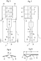
- the contact component is designed as a so-called plug contact 2 for at least one wire 3 of an electrical cable 4.
- the main parts of the contact component 1 are a contact part 5, a spring part 6 and an insertion guide 7 for the wire 3, which inevitably causes the wire to be guided between the contact part 5 and the spring part 6 when inserted.
- the contact part 5 and the spring part 6 are each formed by plate-shaped sheet metal parts which are arranged approximately adjacent to one another with their broad sides and are integrally connected and produced by a bend or fold 8. In the area of the fold 8, the contact part 5 and the spring part 6 with their mutually facing broad sides 5a, 6a can lie against one another or be at a distance from one another.
- the apex 9 of the fold 8 is located on a common side edge for the contact part 5 and the spring part 6. Starting from this side edge or apex 9, the contact part 5 has a greater length L1 than the spring part 6, the length of which is designated L2 .
- the aspect ratio is about 1: 3/4.
- the contact part is also a base part B, which carries the spring part 6.
- the insertion guide 7 is through a bend 11 of the contact part 5 to the side facing away from the spring part 6 and through a through hole 12 for the core 3 educated.
- the bend 11 is arranged approximately centrally with respect to the length L1 of the contact part 5 and it extends over a length range L3 which is approximately 1/3 to 1/2 of the length L1.
- the bend 11, which in the present embodiment is continuous at right angles to the lengths L1, L2, that is to say in the form of a profile, is covered by the spring part 6.
- the spring part can be made so long that its free end edge 14 extends as far as the transition region 15 between the bend 11 and the right-hand side strip 13b in FIG. 1 or projects beyond the transition region 15.
- the push-through hole 12 is preferably located in the end region of the flank 11a which faces the apex 9, its preferably round cross-sectional dimension being dimensioned so large that the wire 3 can assume the position shown in FIG. 4, which bears against the rounded or angular transition 15, or can be inserted in this position in which it includes an acute angle W with the plane E of the strips 14.
- the through hole 12 is punched into a circuit board, the thickness d of which may be approximately 0.3 to 0.6 mm, before the contact component 1 is bent or folded.
- the board is made of spring bronze.
- the contact component 1 has a further plug contact 2 or another electrical contact, with which a further electrical contact can be connected to the wire of a supply or continuation electrical line.
- the spring part 6 is divided into spring fingers 6.1, 6.2, 6.3, each in the presence of several aforementioned plug contacts 2, by separating cuts 17 located between two adjacent through holes 12 independently bias the associated wire 3 against the associated contact point 18.
- the electrical contact takes place both with the contact part 5 and the spring part 6.
- the inner edge of the spring part 6 resting on the associated wire 3 forms a safeguard against unwanted removal of the wire 3 from the plug contact 2, which is ensured due to the relatively strong friction with which the inner edge acts against the wire 3 due to the spring tension.
- the plug contacts 2.1, 2.2, 2.3 can be used to connect both multi-core electrical lines and supply and / or discharge electrical lines 4.
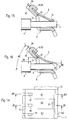
- the contact component 1 is combined with a tapping contact 21, which is provided by two cutting and / or gripping bars 22 is formed, which extend side by side from the contact part 5 approximately in its plane E and have a cutting and / or tapping gap 23 between them.
- the longitudinal edges 22a of the tapping webs 22 delimiting the tapping gap 23 can be blunt, e.g. be formed by simple die cuts or as cutting.
- the gap width b of the tapping gap is to be dimensioned somewhat smaller than the cross-sectional dimension of the line wire to be contacted, so that when tapping the tapping webs 22 bend laterally due to their elasticity and bear against the line wire with a prestress.
- the tapping webs 22 are rounded on their inner corners or provided with bevels 24.
- the tapping gap 23 can be widened, as a result of which the flexibility and elasticity of the engagement webs 22 is increased.
- the tapping webs 22 extend transversely from the lateral strips 13a, 13b, being arranged on both sides of the bend 11.
- the widening 25 can also be arranged for the reason of releasing the tapping webs 22 from the deformation of the bend 11 in that the tapping webs 22 are arranged laterally next to the bend 11 in their foot region.
- the tapping contact 21 is suitable in a known manner for contacting bare as well as insulated line wires (insulation displacement contact), the insulation being a varnish or a thin plastic coating.
- the tapping webs 22 are not arranged in one plane, but instead they close an acute angle W1 of e.g. about 60 to 75 °. This can be done by turning the tapping bars 22 e.g. in the foot area.
- W1 e.g. about 60 to 75 °.
- the advantage of such a configuration is that in the case of a punched tapping gap 23, due to the twisted arrangement of the tapping webs 22, wedge-shaped tapping edges 22a are opposed, which are particularly suitable for cutting through insulation due to the wedge shape.
- the width b1 taken up by both tapping webs 22 is dimensioned somewhat smaller than the length L of the contact part 5, so that in the transition area between the preferably parallel outer edges of the tapping webs 22 and the contact part 5 there are preferably shoulder surfaces 26 on both sides, which when the plug contact 2 is positioned in chambers of a plastic housing (not shown) can serve as positioning stops.
- the bend 11 is not a round, but a triangular cross-sectional shape on the one hand, and on the other hand with regard to Length L1 of the contact part 5 is offset off-center towards its free end, the outer flank 11b of the bend 11 forming the free end of the contact part 5.
- the lengths L1 and L2 of the contact part 5 and the spring part 6 are dimensioned approximately the same size.
- the free edge area of the contact part 5 and / or the spring part 6 can be provided with an outward curve 27.
- the one-sided strips 13a of the contact part 5 for connecting the tapping webs 22 are only available on one side of a longitudinal center plane 28 extending at right angles to the level of the tapping webs 22.
- a flat base section 31 is provided between the contact part 5 and the tapping webs 22, which extends in one piece from the strip 13a and is separated from the rest of the section of the contact part 5 containing the bend 11 by a separating cut 32.
- the separating cut 32 extends from the free end to the foot region of the bend 11.
- the plug contact 2 corresponds to the configuration described above according to FIGS. 7 and 8, but with the tapping contact 21 at least three, starting from the base section 31 and through Separating strand 33 has contact spring tongues 34 which are separate from one another and, with their mutually facing broad sides, bear flat against an associated line wire 35 of a lever 35, which is indicated as indicated.
- the free ends of the spring tongues 34 are provided with outwardly curved bevels or curves 36.
- Such a tapping contact 21 is not suitable for cutting through insulation. For this reason, the line wire 35 in the contact area is freed from insulation, for example a lacquer or plastic coating 35a.
- a comparable plug contact 2 is combined with a tapping contact 21, which has at least two pairs A of opposing contact spring tongues 34, which of has a cross-sectionally U or tubular base section 37 with two opposite broad-side base walls 38a, 38b, from which the contact spring tongue pairs A extend and extend convergent so that they touch in a contact area.
- the separating strands 5 separating the contact spring tongue pairs A are arranged opposite one another and are dimensioned shorter than the length L3 of the contact spring tongues 34, as a result of which the latter are stabilized.
- contact spring tongues 34 are provided with chamfers for easy insertion of the associated line core 35 by rounding 36 arranged at their free ends and pointing outwards.
- the wire 35 also requires removal of the insulation in this exemplary embodiment.
- the end-side base walls 38a, 38c can be connected to one another in a form-fitting manner by means of a positive connection 41 and thus stabilized.
- the form-fitting connection 41 can be formed by an undercut 42 in one base wall 37a and a projection 43 matching the shape and size of the undercut 42, which engage when the base portion 37 is bent into the tubular shape in the manner of a puzzle.
- the contact component 1 is likewise formed by a plug contact 2 and a tapping contact 21 each with a special configuration.
- the tapping contact 21 differs from the tapping contacts according to FIGS. 5 and 8, among other things, in that two cutting and / or tapping web pairs 22B lie opposite one another and start from a U-shaped or tubular base section 37. From Fig. 12 it can be seen that the spring part 6 and the spring fingers 6.1, 6.2, 6.3 diagonally to the tubular Base section 37 are arranged. As in the exemplary embodiment described above, the end walls of the circuit board P shown in FIG. 13 can be connected to one another and stabilized by a positive connection 41.
- the cutting and / or tapping webs 22 are stabilized in several ways. On the one hand, they are less flexible due to the shorter length L4 of the tapping gaps 23, as a result of which a greater clamping force and / or cutting force is achieved. On the other hand, the cutting and / or tapping webs 22 of adjacent cutting and / or tapping web pairs 22B are connected to one another by mutually opposite stabilizing walls 45a, 45b forming the tubular shape, which further reduce the elasticity or resilience and thus the cutting and / or further stabilize tapping bars 22.
- this contact component 1 is that the base section 37, which is U-shaped or tubular in cross section, is integrally connected to the contact part 5 in the region of the inner flank 11a of the bend 11. In the remaining areas, the base section 37 is separated by separating cuts 32.
- the plug contact 2 in this embodiment differs from the plug contact 2 of the embodiment according to FIGS. 7 and 8 in that it has a mirror-image design.
- the length of the strip portion 13a is made shorter, and is about 1/4 to 1/3 the length L of the contact part 5.
- a further connecting part 50 on the contact component 1, in particular a plug contact 51 and / or alligator clips 52, e.g. B. to arrange insulation displacement contact, which preferably also starts from the base part B or another base section and is thus carried by the latter.
- the plug contact 51 and / or tapping contact 52 is formed by a flat tongue 53, which is formed by a preferably one-piece extension of the base part B, in particular an extension transverse to its longitudinal direction, see the length L1 in FIG 2 or 1.
- the tongue 53 can be arranged, inter alia, on the flank 11a or on the flank 11b (FIG. 12), wherein its width can correspond approximately to the length of this flank.
- the tongue 53 can be arranged in one piece on the blank or on the board P and cut or prefabricated by a common punch cut.
- the tongue 53 can have narrow projections 54 on the narrow side, which in the present embodiment have a blunt wedge shape.
- This configuration can, for. B. serve to clamp on the tongue 53 attachable contact shoes. It may be advantageous to provide the flanks of the projections 54 facing away from the free end of the tongue with waves or serrations 55, as is indicated in FIG. 13.
- the tongue 53 can have a tapping gap 23 opening out at the end in the manner described above, which is delimited by lateral tapping webs 22, as has already been described.
- flanks of the projections 54 facing the free end can form insertion bevels for a pluggable plug contact or clamping shoe.
- the connecting part 50 serves as a grounding contact, which with its free end e.g. is pressed into a hole or socket of an earth part or mating contact.
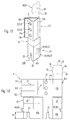
- the contact component 1 is constructed in several pieces, here in two pieces, the spring part 6 being a separate component which is fastened to the base part B with fastening elements 61 .
- the fastening elements 61 are preferably one-piece parts of the base part.
- the fastening elements 61 are formed by tongues 62, which are cut free by cuts 63 in the base part B and bent laterally, each protruding through a fastening hole 64 in the spring part 6 and bent and preferably bent on the side of the spring part 6 facing away from the base part B. are pressed against the spring part 6.
- the free ends of the tongues 62 point in the direction of the free end of the spring part 6.
- the fastening points are arranged in the edge region of the spring part 6 facing away from the free end of the spring part 6. In the present embodiment, three such fastenings are arranged along the unfree edge of the spring part 6.
- FIGS. 14 to 16 A further difference in the configuration according to FIGS. 14 to 16 is described below, which is advantageous both in the case of a two-piece spring part 6 according to FIGS. 14 to 16 and in the case of a one-piece spring part according to FIGS. 1 to 13.
- the free end region of the spring part 6 or here the spring sections or spring fingers 6.1, 6.3 is affected by this further embodiment. While the middle spring finger 6.2 has an outwardly angled or rounded portion 27 in its free end region, the free end of the spring fingers 6.1, 6.3 ends on the inner edge 65, preferably with sharp edges.
- the spring part 6 is arranged in such an inclined position that it is inserted Contact element, e.g.
- a conductor wire 3 or the flank 11b of the bend 11 encloses an angle W1 of approximately 45 to 60 °.
- the length of the spring part 6 is dimensioned so large, taking into account the cross-sectional dimension of the inserted conductor, that the free end region of the spring part 6 is so inclined in the contact position that when the conductor is pulled out, the free end of the spring part 6 leads the conductor either due to the sharp inner edge 65 and the spring tension or due to the latter and its steep arrangement prevents clamping by being pulled out.
- This locking effect is further increased if the free edge region of the spring part is bent or angled toward the conductor by an angle W2 of approximately 3 to 15 °, in particular approximately 5 to 8 °.
- the bend 11 is flat or straight, at least in the region of the flank 11b, so that the inserted conductor can rest on the flank 11b.
- the through hole 12 has a considerable oversize 66 with respect to the relevant transverse dimension of the conductor. Because of this oversize 66, it is possible to pivot the conductor against the hole edge 67 facing away from the contact leg 11b. The angle W1 is thereby reduced, the function of the self-locking clamping action also being overridden. It is thus possible, by swiveling up the arrangement in FIG. 16 and then pulling out the conductor, to solve the plug-in connection in a manner that is easy to handle, while in the original position of the conductor the pulling out is prevented or at least strongly inhibited due to the clamping action described above.
Landscapes
- Coupling Device And Connection With Printed Circuit (AREA)
- Multi-Conductor Connections (AREA)
- Cable Accessories (AREA)
- Connections By Means Of Piercing Elements, Nuts, Or Screws (AREA)
Applications Claiming Priority (2)
| Application Number | Priority Date | Filing Date | Title |
|---|---|---|---|
| DE29607136U | 1996-04-19 | ||
| DE29607136U DE29607136U1 (de) | 1996-04-19 | 1996-04-19 | Kontaktbauteil für einen elektrischen Steckverbinder |
Publications (2)
| Publication Number | Publication Date |
|---|---|
| EP0807993A2 true EP0807993A2 (fr) | 1997-11-19 |
| EP0807993A3 EP0807993A3 (fr) | 2000-01-05 |
Family
ID=8022834
Family Applications (1)
| Application Number | Title | Priority Date | Filing Date |
|---|---|---|---|
| EP97106308A Withdrawn EP0807993A3 (fr) | 1996-04-19 | 1997-04-16 | Elément de contact pour connecteur électrique |
Country Status (2)
| Country | Link |
|---|---|
| EP (1) | EP0807993A3 (fr) |
| DE (1) | DE29607136U1 (fr) |
Cited By (4)
| Publication number | Priority date | Publication date | Assignee | Title |
|---|---|---|---|---|
| GB2355345A (en) * | 1999-10-11 | 2001-04-18 | Bg Electrical Ltd | Screwless electrical terminal |
| FR2841049A1 (fr) * | 2002-06-13 | 2003-12-19 | Legrand Sa | Connecteur comportant une barette metallique pour la connexion de conducteurs electriques |
| FR2841050A1 (fr) * | 2002-06-13 | 2003-12-19 | Legrand Sa | Connecteur comportant une barrette matallique pour la connexion de conducteurs electriques |
| EP1855353A3 (fr) * | 2006-04-21 | 2008-05-28 | Wago Verwaltungsgesellschaft mbH | Borne de connexion électrique |
Family Cites Families (2)
| Publication number | Priority date | Publication date | Assignee | Title |
|---|---|---|---|---|
| AT379921B (de) * | 1983-03-21 | 1986-03-10 | Electro Terminal Gmbh | Elektrischer verbinder |
| GB2300757B (en) * | 1995-05-09 | 1998-12-23 | Bun Wong | Rotary stepping switch |
-
1996
- 1996-04-19 DE DE29607136U patent/DE29607136U1/de not_active Expired - Lifetime
-
1997
- 1997-04-16 EP EP97106308A patent/EP0807993A3/fr not_active Withdrawn
Cited By (5)
| Publication number | Priority date | Publication date | Assignee | Title |
|---|---|---|---|---|
| GB2355345A (en) * | 1999-10-11 | 2001-04-18 | Bg Electrical Ltd | Screwless electrical terminal |
| GB2355345B (en) * | 1999-10-11 | 2003-04-09 | Bg Electrical Ltd | A screwless electrical terminal |
| FR2841049A1 (fr) * | 2002-06-13 | 2003-12-19 | Legrand Sa | Connecteur comportant une barette metallique pour la connexion de conducteurs electriques |
| FR2841050A1 (fr) * | 2002-06-13 | 2003-12-19 | Legrand Sa | Connecteur comportant une barrette matallique pour la connexion de conducteurs electriques |
| EP1855353A3 (fr) * | 2006-04-21 | 2008-05-28 | Wago Verwaltungsgesellschaft mbH | Borne de connexion électrique |
Also Published As
| Publication number | Publication date |
|---|---|
| DE29607136U1 (de) | 1997-08-21 |
| EP0807993A3 (fr) | 2000-01-05 |
Similar Documents
| Publication | Publication Date | Title |
|---|---|---|
| DE69403539T2 (de) | Elektrische Anschlussbuchse | |
| DE2414640C3 (de) | Elektrischer Verbinder mit einer metallischen Anschlußklemme | |
| DE2737328C2 (fr) | ||
| DE3127704C2 (de) | Verbinder zum Anschließen eines Vielleiter-Flachkabels | |
| DE69300322T2 (de) | Elektrische Kontaktzunge mit doppelter Dicke. | |
| DE68909708T2 (de) | Elektrisches Kontaktglied. | |
| DE2711723C2 (de) | Verfahren zum Anschließen eines feinen Drahtes und Verbinder zur Durchführung dieses Verfahrens | |
| DE69602306T2 (de) | Elektrischer Verbinder | |
| DE69324773T2 (de) | Elektrisches Verbindungselement für Flachbandkabel | |
| DE69403428T2 (de) | Elektrischer Verbinder und Anschlusselement dafür zur Verbindung mit ein Messerkontakt | |
| DE8713038U1 (de) | Buchsenartiger elektrischer Anschluß | |
| DE69416079T2 (de) | Klemmverbinder | |
| DE69206615T2 (de) | Elektrische verbinder. | |
| DE2925938A1 (de) | Elektrischer flachsteckverbinder | |
| DE2201099C2 (de) | Quetschklemme | |
| DE2425462C2 (de) | Elektrischer Buchsenkontakt | |
| DE19734476C2 (de) | Crimpanschluss | |
| DE69606031T2 (de) | Kabelverbindungssystem | |
| DE19949387A1 (de) | Kontaktteil für Anschlussklemme | |
| DE2013883C3 (de) | Aus elastischem Kunststoffmaterial geformtes Isoliergehäuse | |
| DE69419576T2 (de) | Elektrische Anschlussklemme zum Aufpressen an einen Leiter | |
| DE2506942A1 (de) | Lampenfassung | |
| DE69913397T2 (de) | Schneidklemme | |
| DE69606032T2 (de) | Artikelzweckdienlich zur markierung und verfahren zur markierung davon | |
| EP0807993A2 (fr) | Elément de contact pour connecteur électrique |
Legal Events
| Date | Code | Title | Description |
|---|---|---|---|
| PUAI | Public reference made under article 153(3) epc to a published international application that has entered the european phase |
Free format text: ORIGINAL CODE: 0009012 |
|
| AK | Designated contracting states |
Kind code of ref document: A2 Designated state(s): AT DE ES FR GB IT SE |
|
| PUAL | Search report despatched |
Free format text: ORIGINAL CODE: 0009013 |
|
| AK | Designated contracting states |
Kind code of ref document: A3 Designated state(s): AT DE ES FR GB IT SE |
|
| 17P | Request for examination filed |
Effective date: 20000705 |
|
| RAP1 | Party data changed (applicant data changed or rights of an application transferred) |
Owner name: ELECTRO-TERMINAL GMBH & CO. KG |
|
| RAP1 | Party data changed (applicant data changed or rights of an application transferred) |
Owner name: TRIDONICATCO CONNECTIONTECHNOLOGY GMBH & CO KG |
|
| STAA | Information on the status of an ep patent application or granted ep patent |
Free format text: STATUS: THE APPLICATION IS DEEMED TO BE WITHDRAWN |
|
| 18D | Application deemed to be withdrawn |
Effective date: 20060119 |