EP0807813B1 - Dispositif de mesure des paramètres physiologiques du sang dans un système circulaire extracorporel - Google Patents
Dispositif de mesure des paramètres physiologiques du sang dans un système circulaire extracorporel Download PDFInfo
- Publication number
- EP0807813B1 EP0807813B1 EP97106007A EP97106007A EP0807813B1 EP 0807813 B1 EP0807813 B1 EP 0807813B1 EP 97106007 A EP97106007 A EP 97106007A EP 97106007 A EP97106007 A EP 97106007A EP 0807813 B1 EP0807813 B1 EP 0807813B1
- Authority
- EP
- European Patent Office
- Prior art keywords
- light
- cavity
- light sources
- spherical cavity
- blood
- Prior art date
- Legal status (The legal status is an assumption and is not a legal conclusion. Google has not performed a legal analysis and makes no representation as to the accuracy of the status listed.)
- Expired - Lifetime
Links
Images

Classifications
-
- G—PHYSICS
- G01—MEASURING; TESTING
- G01N—INVESTIGATING OR ANALYSING MATERIALS BY DETERMINING THEIR CHEMICAL OR PHYSICAL PROPERTIES
- G01N21/00—Investigating or analysing materials by the use of optical means, i.e. using sub-millimetre waves, infrared, visible or ultraviolet light
- G01N21/17—Systems in which incident light is modified in accordance with the properties of the material investigated
- G01N21/25—Colour; Spectral properties, i.e. comparison of effect of material on the light at two or more different wavelengths or wavelength bands
- G01N21/255—Details, e.g. use of specially adapted sources, lighting or optical systems
-
- G—PHYSICS
- G01—MEASURING; TESTING
- G01N—INVESTIGATING OR ANALYSING MATERIALS BY DETERMINING THEIR CHEMICAL OR PHYSICAL PROPERTIES
- G01N21/00—Investigating or analysing materials by the use of optical means, i.e. using sub-millimetre waves, infrared, visible or ultraviolet light
- G01N21/17—Systems in which incident light is modified in accordance with the properties of the material investigated
- G01N21/25—Colour; Spectral properties, i.e. comparison of effect of material on the light at two or more different wavelengths or wavelength bands
- G01N21/31—Investigating relative effect of material at wavelengths characteristic of specific elements or molecules, e.g. atomic absorption spectrometry
- G01N21/314—Investigating relative effect of material at wavelengths characteristic of specific elements or molecules, e.g. atomic absorption spectrometry with comparison of measurements at specific and non-specific wavelengths
- G01N21/3151—Investigating relative effect of material at wavelengths characteristic of specific elements or molecules, e.g. atomic absorption spectrometry with comparison of measurements at specific and non-specific wavelengths using two sources of radiation of different wavelengths
-
- G—PHYSICS
- G01—MEASURING; TESTING
- G01N—INVESTIGATING OR ANALYSING MATERIALS BY DETERMINING THEIR CHEMICAL OR PHYSICAL PROPERTIES
- G01N21/00—Investigating or analysing materials by the use of optical means, i.e. using sub-millimetre waves, infrared, visible or ultraviolet light
- G01N21/17—Systems in which incident light is modified in accordance with the properties of the material investigated
- G01N21/25—Colour; Spectral properties, i.e. comparison of effect of material on the light at two or more different wavelengths or wavelength bands
- G01N21/31—Investigating relative effect of material at wavelengths characteristic of specific elements or molecules, e.g. atomic absorption spectrometry
- G01N21/314—Investigating relative effect of material at wavelengths characteristic of specific elements or molecules, e.g. atomic absorption spectrometry with comparison of measurements at specific and non-specific wavelengths
- G01N2021/3144—Investigating relative effect of material at wavelengths characteristic of specific elements or molecules, e.g. atomic absorption spectrometry with comparison of measurements at specific and non-specific wavelengths for oxymetry
-
- G—PHYSICS
- G01—MEASURING; TESTING
- G01N—INVESTIGATING OR ANALYSING MATERIALS BY DETERMINING THEIR CHEMICAL OR PHYSICAL PROPERTIES
- G01N2201/00—Features of devices classified in G01N21/00
- G01N2201/02—Mechanical
- G01N2201/022—Casings
- G01N2201/0224—Pivoting casing
-
- G—PHYSICS
- G01—MEASURING; TESTING
- G01N—INVESTIGATING OR ANALYSING MATERIALS BY DETERMINING THEIR CHEMICAL OR PHYSICAL PROPERTIES
- G01N2201/00—Features of devices classified in G01N21/00
- G01N2201/06—Illumination; Optics
- G01N2201/061—Sources
- G01N2201/06113—Coherent sources; lasers
- G01N2201/0612—Laser diodes
-
- G—PHYSICS
- G01—MEASURING; TESTING
- G01N—INVESTIGATING OR ANALYSING MATERIALS BY DETERMINING THEIR CHEMICAL OR PHYSICAL PROPERTIES
- G01N2201/00—Features of devices classified in G01N21/00
- G01N2201/06—Illumination; Optics
- G01N2201/064—Stray light conditioning
-
- G—PHYSICS
- G01—MEASURING; TESTING
- G01N—INVESTIGATING OR ANALYSING MATERIALS BY DETERMINING THEIR CHEMICAL OR PHYSICAL PROPERTIES
- G01N2201/00—Features of devices classified in G01N21/00
- G01N2201/06—Illumination; Optics
- G01N2201/065—Integrating spheres
Definitions
- the invention relates to a device for the measurement of physiological parameters of blood guided in an extracorporeal circuit.
- the physiological parameters on the basis of which the efficiency of the extracorporeal circulation can be assessed include, among others, the blood gas values, in particular the oxygen saturation of the blood before and after the extracorporeal oxygenation. Only when these values are constantly being determined can the extracorporeal circulation be adjusted for blood flow and oxygenation. But hematocrit is also an important factor in the assessment of extracorporeal blood.
- Optical measurement methods on extracorporeal circulating blood for example in operations on the cardiovascular system with the aid of a heart-lung machine (HLM) exploit the fact that from a change in the optical behavior of the blood to changes in the microscopic properties of the blood and thus the physiological parameters influencing them can be closed. Both the backscattering or transmission behavior as well as the spatial distribution of absorption rates and Radiation distributions.
- HLM heart-lung machine
- US Pat. No. 4,444,498 discloses an optical measuring arrangement in which a cuvette having a planar window through which two light-emitting diodes radiate light of different wavelength into the blood guided through the cuvette is inserted into the extracorporeal circuit.
- the light reflected through the window is picked up by a photo sensor and the sensor signal is evaluated.
- the sensor signal is inherently dependent on the distance to the cuvette window, the angle and the distance and angle of the light sources.
- US Pat. No. 5,422,483 discloses an analysis device which uses a light source operating in the infrared range to analyze a sample introduced into a sample holder.
- the measuring light is received in an integrating sphere and hits the sample there.
- the light diffusely reflected by the sample is effectively collected by the inner wall of the integrating sphere.
- US Pat. No. 4,320,978 discloses a device in which cylindrical sample cells pass through an integrating sphere and are irradiated with a measuring light.
- a sensor disposed on the ball wall receives the light scattered from the cylindrical sample cell, which is reflected on the inner wall of the integrating sphere.
- the invention is based on the object of providing a device which is suitable for measuring physiological parameters of blood conducted in an extracorporeal circuit without the use of disposable sensors and / or disposable cuvettes and which provides the measured values which provide control of allow physiological parameters, in particular the blood gas values and in particular the oxygen saturation.
- FIG. 1 shows a first embodiment of the device according to the invention for the measurement of physiological parameters of blood conveyed in an extracorporeal circulation.
- the device comprises two light sources 1a and 1b and at least one sensor device 2.
- the light sources 1a and 1b emit light of different wavelengths.
- the light of a light source 1a preferably has a wavelength of about 805 nm, since for this value, the spectral response of human whole blood is independent of the degree of oxygenation (isobestic point).
- the light of the second light source 1b has a different wavelength, preferably either in the range from 630 nm to 780 nm or in the range from 980 nm to 1080 nm.
- Both light sources 1a and 1b emit their light into a spherical cavity 3, which has a reflective, preferably diffusely highly reflective, inner surface. Particularly suitable is a uniform matt white surface, which follows the law of Lambert's radiator. Light emitted into the spherical cavity, which impinges on the inner surface, is diffusely reflected, so that a homogeneous power density arises on the inner surface of the cavity, which can be detected independently of angle with the aid of the light sensor device 2.
- the light sensor device 2 is arranged so that it receives a part of the propagating in the spherical cavity light.
- the device according to the invention also has a second cavity 4, in which a tube section of the extracorporeal blood circulation can be inserted.
- the second cavity 4 is configured and arranged relative to the first, spherical cavity 3 so that when inserted hose emitted from the light sources 1a and 1b light L a and L b practically only on the interface between the blood and the inner wall of the Hose hits.
- the values determined with the aid of this device according to the invention allow a very accurate determination of the the oxygen saturation, so that the device according to the invention for the regulatory use in an extracorporeal blood circulation is suitable.
- the output signal of the light sensor device 2 can be used as an input signal of a control loop, with which the oxygen content of the blood is influenced by controlling an oxygenator through which the blood is conducted in the extracorporeal circuit.
- the second cavity 4 penetrates the first, spherical cavity 3 in regions.
- the second cavity 4 may also be arranged so as to penetrate the first spherical cavity 3 in its entire cross section.
- the second cavity 4 may be located so that it receives the center of the first, spherical cavity 3.
- the second cavity 4 advantageously has a cylindrical shape and preferably has a circular cross-section perpendicular to the longitudinal axis, as shown in FIG.
- the second cavity 4 can have a cross-section which deviates from the circular shape, for example an elliptical cross section, perpendicular to the longitudinal axis, in which case the main axis of the elliptical cross section preferably extends into the first, spherical cavity 3.
- the tube is usually flexible in an extracopralal circuit, its shape can be readily adapted to the shape of the second cavity 4 when inserted.
- the second cavity 4 is dimensioned so that the outer wall of the tube rests against the inner wall of the second cavity 4.
- the second cavity 4 protrudes into the first, spherical cavity 3, but especially in the last-mentioned cylindrical configuration with elliptical cross-section, opens up the possibility of using the output signal of the light sensor device hematocrit promoted in the extracorporeal circuit Blood as the light scattering volume in the blood increases with decreasing hematocrit. As a result, increasingly stray light exits laterally from the cavity 4 and penetrates into the cavity 3. By a suitable evaluation of the proportion of the sensor signal caused by the scattered light, the hematocrit can be determined.
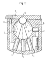
- a second embodiment which also has the basic elements of the first embodiment, but which is equipped with the aim of further increasing the accuracy, and in terms of practical use with further features.
- the light sources 1 shown in the second embodiment are laser light sources and preferably have an integrated collimator optics, with the help of an accurate focusing of the laser light on the interface between blood and tube inner wall is possible. An adjustment of the device is then no longer necessary.
- the laser light sources 1 of the second exemplary embodiment are preferably laser diodes, which advantageously each have an integrated measuring diode (not shown) which corresponds to one of the radiated laser light power Signal generated. With the help of this measurement signal, the laser light power can be controlled.
- a wall member 5 is provided which is permeable to the light emitted from the laser light sources 1 but not to unwanted ambient light.
- the shape of the wall member 5 preferably follows the shape of the second cavity 4 and thereby is regularly adapted to the shape of the tube portion or supports the adaptation of the flexible tube to the shape of the second cavity 4.
- Between the first cavity 3 and the light sensor device 2 is preferably provided for the light of the light sources 1 permeable wall element 10, however, blocks unwanted ambient light.
- the second cavity 4 is formed only in part in a base body 6, which receives at least the first, spherical cavity 3.
- the laser light sources 1 and the light sensor device 2 are also accommodated in the base body.
- the second cavity 4 is completed by a further part, which is formed in a cover 7 pivotally mounted on the base body. If the cover 7 is opened, the tube section can be inserted into the part of the second cavity 4 formed in the main body or taken out there. For the measurement, the cover 7 is closed, so that the tube portion securely held in the second cavity 4 and the irradiation of ambient light is prevented.
- a detector 8 is preferably provided provided, which detects the closed pivot position of the cover 7 and whose output signal is used to interrupt the radiation of laser light when the cover 7 is opened.
Landscapes
- Physics & Mathematics (AREA)
- Spectroscopy & Molecular Physics (AREA)
- Health & Medical Sciences (AREA)
- Analytical Chemistry (AREA)
- Life Sciences & Earth Sciences (AREA)
- Chemical & Material Sciences (AREA)
- Biochemistry (AREA)
- General Health & Medical Sciences (AREA)
- General Physics & Mathematics (AREA)
- Immunology (AREA)
- Pathology (AREA)
- Toxicology (AREA)
- Measurement Of The Respiration, Hearing Ability, Form, And Blood Characteristics Of Living Organisms (AREA)
- Investigating Or Analysing Materials By Optical Means (AREA)
Claims (15)
- Dispositif pour la mesure de paramètres physiologiques du sang transporté dans un circuit extracorporel, comprenant- au moins deux sources de lumière (1a, 1b) qui émettent de la lumière à une longueur d'onde différente,- au moins un dispositif de détection de lumière (2),- un premier espace creux de forme sphérique (3) avec une surface intérieure (3a) réfléchissante dans lequel rayonnent les sources de lumière (1a, 1b) et depuis lequel le dispositif de détection de lumière (2) reçoit une partie de la lumière qui se diffuse dans le premier espace creux de forme sphérique (3), et- un deuxième espace creux (4) dans lequel peut être déposée une section de tuyau du circuit extracorporel et qui est configuré et disposé par rapport au premier espace creux de forme sphérique (3) de telle sorte que lorsque le tuyau y est déposé, la lumière (La, Lb) émise par les sources de lumière ne vient pratiquement heurter que la surface de délimitation entre le sang et une paroi intérieure du tuyau sans qu'il se produise une radiation incidente directe sur la surface intérieure (3a) du premier espace creux de forme sphérique (3), à l'exception d'une lumière parasite négligeable, et retourne au moins partiellement dans le premier espace creux de forme sphérique (3) par réflexion et/ou transmission.
- Dispositif selon la revendication 1, caractérisé en ce que le deuxième espace creux (4) traverse le premier espace creux de forme sphérique (3) au moins par zones.
- Dispositif selon l'une des revendications 1 ou 2, caractérisé en ce que le deuxième espace creux (4) est cylindrique.
- Dispositif selon la revendication 3, caractérisé en ce que le deuxième espace creux (4) présente perpendiculairement à l'axe longitudinal une section transversale circulaire.
- Dispositif selon la revendication 3, caractérisé en ce que le deuxième espace creux (4) présente perpendiculairement à l'axe longitudinal une section transversale elliptique.
- Dispositif selon la revendication 5, caractérisé en ce que le deuxième espace creux (4) est disposé de telle sorte que l'axe principal de la section transversale elliptique s'étend vers l'intérieur du premier espace creux de forme sphérique (3).
- Dispositif selon l'une des revendications 1 à 6, caractérisé en ce que les sources de lumière sont des sources de lumière laser (1).
- Dispositif selon la revendication 7, caractérisé en ce que les sources de lumière laser (1) présentent un optique collimateur.
- Dispositif selon l'une des revendications 7 ou 8, caractérisé en ce que les sources de lumière laser (1) sont des diodes laser.
- Dispositif selon la revendication 9, caractérisé en ce que les diodes laser (1) présentent respectivement une diode de mesure intégrée qui génère un signal correspondant à la puissance de la lumière laser émise.
- Dispositif selon l'une des revendications 1 à 10, caractérisé en ce que l'une des sources de lumière (1a ; 1) émet de la lumière à une longueur d'onde d'environ 805 nm et l'autre des sources de lumière (1b ; 1) émet de la lumière à une longueur d'onde comprise soit dans la plage de 630 nm à 780 nm, soit dans la plage de 980 nm à 1080 nm.
- Dispositif selon l'une des revendications 1 à 11, caractérisé en ce qu'entre le premier espace creux de forme sphérique (3) et le deuxième espace creux (4) est prévu un élément de paroi (5) transparent pour la lumière des sources de lumière, mais qui bloque cependant de la lumière ambiante indésirable.
- Dispositif selon l'une des revendications 1 à 12, caractérisé en ce qu'entre le premier espace creux de forme sphérique (3) et le dispositif de détection de lumière (2) est prévu un élément de paroi (10) transparent pour la lumière des sources de lumière (1), mais qui bloque cependant de la lumière ambiante indésirable.
- Dispositif selon l'une des revendications 1 à 13, caractérisé en ce qu'il est prévu un corps de base (6) pour la réception du premier espace creux de forme sphérique (3) et une partie du deuxième espace creux (4) ainsi qu'un corps (7) qui est mobile, de préférence pivotant, par rapport au corps de base (6) pour la réception d'une autre partie du deuxième espace creux (4).
- Dispositif selon la revendication 14, caractérisé en ce qu'il est prévu un détecteur (8) pour détecter la position de pivotement fermée du corps (7) par rapport au corps de base (6).
Applications Claiming Priority (2)
| Application Number | Priority Date | Filing Date | Title |
|---|---|---|---|
| DE19619513 | 1996-05-14 | ||
| DE19619513A DE19619513C2 (de) | 1996-05-14 | 1996-05-14 | Vorrichtung für die Messung physiologischer Parameter von in einem extrakorporalen Kreislauf geführtem Blut |
Publications (3)
| Publication Number | Publication Date |
|---|---|
| EP0807813A2 EP0807813A2 (fr) | 1997-11-19 |
| EP0807813A3 EP0807813A3 (fr) | 1998-06-24 |
| EP0807813B1 true EP0807813B1 (fr) | 2006-12-06 |
Family
ID=7794339
Family Applications (1)
| Application Number | Title | Priority Date | Filing Date |
|---|---|---|---|
| EP97106007A Expired - Lifetime EP0807813B1 (fr) | 1996-05-14 | 1997-04-11 | Dispositif de mesure des paramètres physiologiques du sang dans un système circulaire extracorporel |
Country Status (3)
| Country | Link |
|---|---|
| US (1) | US5838429A (fr) |
| EP (1) | EP0807813B1 (fr) |
| DE (2) | DE19619513C2 (fr) |
Cited By (1)
| Publication number | Priority date | Publication date | Assignee | Title |
|---|---|---|---|---|
| DE102020104266B3 (de) * | 2020-02-18 | 2021-04-22 | Technische Hochschule Lübeck | Vorrichtung und Methode zur Analyse von Blut |
Families Citing this family (11)
| Publication number | Priority date | Publication date | Assignee | Title |
|---|---|---|---|---|
| DE19816487A1 (de) * | 1998-04-14 | 1999-10-21 | Bodenseewerk Perkin Elmer Co | Vorrichtung zum Nachweis eines Fluoreszenzfarbstoffs |
| DE19922812C2 (de) * | 1999-05-19 | 2001-10-25 | Merck Patent Gmbh | Messung von Trübungen mittels Reflektometrie |
| JP4129867B2 (ja) * | 2002-07-18 | 2008-08-06 | 日機装株式会社 | ヘマトクリットセンサ |
| ATE357652T1 (de) * | 2002-12-20 | 2007-04-15 | Optoq Ab | Verfahren und vorrichtung für messungen im blut |
| US7119899B2 (en) * | 2003-07-23 | 2006-10-10 | Lighthouse Worldwide Solutions, Inc | Particle sensor system |
| US7763454B2 (en) * | 2004-07-09 | 2010-07-27 | Church & Dwight Co., Inc. | Electronic analyte assaying device |
| US7502110B2 (en) * | 2004-07-21 | 2009-03-10 | Lighthouse Worldwide Solutions, Inc | Design for particle sensor system |
| US20100004518A1 (en) | 2008-07-03 | 2010-01-07 | Masimo Laboratories, Inc. | Heat sink for noninvasive medical sensor |
| US8630691B2 (en) | 2008-08-04 | 2014-01-14 | Cercacor Laboratories, Inc. | Multi-stream sensor front ends for noninvasive measurement of blood constituents |
| WO2017171650A1 (fr) * | 2016-03-30 | 2017-10-05 | Agency For Science, Technology And Research | Système et procédé d'analyse de fluide |
| US10753870B2 (en) * | 2016-09-14 | 2020-08-25 | Hitachi High-Tech Corporation | Automatic analysis apparatus including a reaction container holding part having a surface that reflects light emitted from a light source |
Citations (2)
| Publication number | Priority date | Publication date | Assignee | Title |
|---|---|---|---|---|
| US4320978A (en) * | 1978-12-12 | 1982-03-23 | Ko Sato | Integration sphere type turbidimeter |
| US5422483A (en) * | 1992-07-31 | 1995-06-06 | Shimadzu Corporation | Near infrared analyzer |
Family Cites Families (14)
| Publication number | Priority date | Publication date | Assignee | Title |
|---|---|---|---|---|
| US4444498A (en) * | 1981-02-27 | 1984-04-24 | Bentley Laboratories | Apparatus and method for measuring blood oxygen saturation |
| DE3138878A1 (de) * | 1981-09-30 | 1983-04-14 | Boehringer Mannheim Gmbh, 6800 Mannheim | Messeinrichtung, insbesondere ulbricht'sche kugel |
| US4485820A (en) * | 1982-05-10 | 1984-12-04 | The Johns Hopkins University | Method and apparatus for the continuous monitoring of hemoglobin saturation in the blood of premature infants |
| CA1218248A (fr) * | 1983-06-30 | 1987-02-24 | Clive K. Coogan | Mesure optique des parametres d'un fluide |
| DE3530689A1 (de) * | 1985-08-28 | 1987-03-12 | Siegfried Dipl Phys Stiller | Methode zur kontinuierlichen messung der haemoglobinkonzentration im extrakorporalen kreislauf |
| DE3534973C2 (de) * | 1985-10-01 | 1995-02-09 | Eppendorf Geraetebau Netheler | Durchflußimpulsphotometer zur Partikelmessung |
| JPS62155834A (ja) * | 1985-12-27 | 1987-07-10 | シチズン時計株式会社 | 血液ガス連続モニタ装置 |
| JPH0827235B2 (ja) * | 1987-11-17 | 1996-03-21 | 倉敷紡績株式会社 | 糖類濃度の分光学的測定法 |
| US4867559A (en) * | 1988-01-06 | 1989-09-19 | Amoco Corporation | Liquid/liquid fiber-optic fluorescence detector and absorbance analyzer |
| US4942305A (en) * | 1989-05-12 | 1990-07-17 | Pacific Scientific Company | Integrating sphere aerosol particle detector |
| US5164597A (en) * | 1989-09-29 | 1992-11-17 | University Of Kentucky Research Foundation | Method and apparatus for detecting microorganisms within a liquid product in a sealed vial |
| DE4024929A1 (de) * | 1990-08-06 | 1992-02-13 | Gao Ges Automation Org | Ulbrichtkugel |
| US5251004A (en) * | 1992-03-13 | 1993-10-05 | Pdt Systems, Inc. | Integrating sphere power meter |
| US5533509A (en) * | 1993-08-12 | 1996-07-09 | Kurashiki Boseki Kabushiki Kaisha | Method and apparatus for non-invasive measurement of blood sugar level |
-
1996
- 1996-05-14 DE DE19619513A patent/DE19619513C2/de not_active Expired - Fee Related
-
1997
- 1997-04-11 DE DE59712774T patent/DE59712774D1/de not_active Expired - Fee Related
- 1997-04-11 EP EP97106007A patent/EP0807813B1/fr not_active Expired - Lifetime
- 1997-05-14 US US08/855,918 patent/US5838429A/en not_active Expired - Lifetime
Patent Citations (2)
| Publication number | Priority date | Publication date | Assignee | Title |
|---|---|---|---|---|
| US4320978A (en) * | 1978-12-12 | 1982-03-23 | Ko Sato | Integration sphere type turbidimeter |
| US5422483A (en) * | 1992-07-31 | 1995-06-06 | Shimadzu Corporation | Near infrared analyzer |
Cited By (2)
| Publication number | Priority date | Publication date | Assignee | Title |
|---|---|---|---|---|
| DE102020104266B3 (de) * | 2020-02-18 | 2021-04-22 | Technische Hochschule Lübeck | Vorrichtung und Methode zur Analyse von Blut |
| WO2021164818A1 (fr) | 2020-02-18 | 2021-08-26 | Technische Hochschule Lübeck | Appareil et procédé d'analyse du sang |
Also Published As
| Publication number | Publication date |
|---|---|
| DE19619513A1 (de) | 1997-11-20 |
| EP0807813A3 (fr) | 1998-06-24 |
| DE19619513C2 (de) | 2001-03-22 |
| EP0807813A2 (fr) | 1997-11-19 |
| DE59712774D1 (de) | 2007-01-18 |
| US5838429A (en) | 1998-11-17 |
Similar Documents
| Publication | Publication Date | Title |
|---|---|---|
| EP0818682B1 (fr) | Procédé et dispositif pour la détermination optique de la concentration de l'hémoglobine totale | |
| DE3876321T2 (de) | Kopf zur messung des reflexionsvermoegens von entfernten proben. | |
| DE69218966T2 (de) | Verbessertes nichtinvasives quantitatives messinstrument im nahen infrarot | |
| DE69724351T2 (de) | System zur Messung von Gewebe-Chromophoren | |
| EP0603658B1 (fr) | Méthode pour déterminer in-vivo d'une propriété optique du liquide de l'humeur vitrée de l'oeil | |
| EP0807813B1 (fr) | Dispositif de mesure des paramètres physiologiques du sang dans un système circulaire extracorporel | |
| DE19952215C2 (de) | Testelement-Analysesystem | |
| EP0154875B1 (fr) | Appareil pour la détermination de la réflectivité diffuse d'un surface échantillon de petites dimensions | |
| DE69636403T2 (de) | Spektrometrie und optisches Messverfahren und Vorrichtung | |
| DE3878595T2 (de) | Geraet zur anzeige von augenleiden. | |
| DE3210593A1 (de) | Vorrichtung zum messen des oxido-reduktionszustands eines organs am lebenden objekt | |
| EP1463443A2 (fr) | Procede et dispositif de determination d'un parametre de transport de lumiere et d'un analyte dans une matrice biologique | |
| DE102006029899A1 (de) | Spektroskopischer Detektor und Verfahren zur Bestimmung von Blut und biologischen Markersubstanzen in Flüssigkeiten | |
| WO2007090378A2 (fr) | Dispositif de mesure destiné à déterminer la dimension, la répartition dimensionnelle et la quantité de particules à l'échelle nanoscopique | |
| WO1997027469A1 (fr) | Procede et dispositif de determination d'un analyte contenu dans une matrice de diffusion | |
| DE2733957A1 (de) | Verfahren und vorrichtung zur messung einer eigenschaft eines materials in blattform | |
| DE2818674B2 (de) | Vorrichtung zum Vermessen von Eigenschaften optischer Fasern | |
| DE60114719T2 (de) | Verfahren und Einrichtung zur Optimierung der Verwendung einer Bräunungseinrichtung | |
| DE69633468T2 (de) | Spektroskopische messungen an lichtstreuendem prüfgut mittels integrations -hohlraum | |
| DE2000931A1 (de) | Verfahren und Geraet zur Messung von Bilirubin in Blutserum | |
| EP3671184B1 (fr) | Dispositif de détection d'alcool doté de canaux de mesure redondants et procédé pour détecter d'alcool | |
| DE3885341T2 (de) | Gerät zur Diagnostik von Augenleiden. | |
| EP1054252B1 (fr) | Dispositif de mesure optique pour déterminer le rayonnement transmis et diffusé | |
| WO2018149921A1 (fr) | Procédé et dispositif d'étalonnage de dispositifs de détection de sang ou de constituants sanguins dans un liquide | |
| WO1997013448A2 (fr) | Dispositif de dosage de la glycemie |
Legal Events
| Date | Code | Title | Description |
|---|---|---|---|
| PUAI | Public reference made under article 153(3) epc to a published international application that has entered the european phase |
Free format text: ORIGINAL CODE: 0009012 |
|
| AK | Designated contracting states |
Kind code of ref document: A2 Designated state(s): DE FR GB IT |
|
| PUAL | Search report despatched |
Free format text: ORIGINAL CODE: 0009013 |
|
| RHK1 | Main classification (correction) |
Ipc: G01N 21/55 |
|
| AK | Designated contracting states |
Kind code of ref document: A3 Designated state(s): DE FR GB IT |
|
| 17P | Request for examination filed |
Effective date: 19980722 |
|
| RAP1 | Party data changed (applicant data changed or rights of an application transferred) |
Owner name: STOECKERT INSTRUMENTE GMBH |
|
| RAP1 | Party data changed (applicant data changed or rights of an application transferred) |
Owner name: SORIN GROUP DEUTSCHLAND GMBH |
|
| GRAP | Despatch of communication of intention to grant a patent |
Free format text: ORIGINAL CODE: EPIDOSNIGR1 |
|
| GRAS | Grant fee paid |
Free format text: ORIGINAL CODE: EPIDOSNIGR3 |
|
| GRAA | (expected) grant |
Free format text: ORIGINAL CODE: 0009210 |
|
| AK | Designated contracting states |
Kind code of ref document: B1 Designated state(s): DE FR GB IT |
|
| PG25 | Lapsed in a contracting state [announced via postgrant information from national office to epo] |
Ref country code: IT Free format text: LAPSE BECAUSE OF FAILURE TO SUBMIT A TRANSLATION OF THE DESCRIPTION OR TO PAY THE FEE WITHIN THE PRESCRIBED TIME-LIMIT;WARNING: LAPSES OF ITALIAN PATENTS WITH EFFECTIVE DATE BEFORE 2007 MAY HAVE OCCURRED AT ANY TIME BEFORE 2007. THE CORRECT EFFECTIVE DATE MAY BE DIFFERENT FROM THE ONE RECORDED. Effective date: 20061206 |
|
| REG | Reference to a national code |
Ref country code: GB Ref legal event code: FG4D Free format text: NOT ENGLISH |
|
| RIN1 | Information on inventor provided before grant (corrected) |
Inventor name: HAHN, ANDREAS, DIPL.-ING. |
|
| REF | Corresponds to: |
Ref document number: 59712774 Country of ref document: DE Date of ref document: 20070118 Kind code of ref document: P |
|
| GBV | Gb: ep patent (uk) treated as always having been void in accordance with gb section 77(7)/1977 [no translation filed] |
Effective date: 20061206 |
|
| EN | Fr: translation not filed | ||
| PLBE | No opposition filed within time limit |
Free format text: ORIGINAL CODE: 0009261 |
|
| STAA | Information on the status of an ep patent application or granted ep patent |
Free format text: STATUS: NO OPPOSITION FILED WITHIN TIME LIMIT |
|
| 26N | No opposition filed |
Effective date: 20070907 |
|
| PG25 | Lapsed in a contracting state [announced via postgrant information from national office to epo] |
Ref country code: GB Free format text: LAPSE BECAUSE OF FAILURE TO SUBMIT A TRANSLATION OF THE DESCRIPTION OR TO PAY THE FEE WITHIN THE PRESCRIBED TIME-LIMIT Effective date: 20061206 |
|
| PG25 | Lapsed in a contracting state [announced via postgrant information from national office to epo] |
Ref country code: DE Free format text: LAPSE BECAUSE OF NON-PAYMENT OF DUE FEES Effective date: 20071101 |
|
| PG25 | Lapsed in a contracting state [announced via postgrant information from national office to epo] |
Ref country code: FR Free format text: LAPSE BECAUSE OF FAILURE TO SUBMIT A TRANSLATION OF THE DESCRIPTION OR TO PAY THE FEE WITHIN THE PRESCRIBED TIME-LIMIT Effective date: 20070727 |
|
| PG25 | Lapsed in a contracting state [announced via postgrant information from national office to epo] |
Ref country code: FR Free format text: LAPSE BECAUSE OF FAILURE TO SUBMIT A TRANSLATION OF THE DESCRIPTION OR TO PAY THE FEE WITHIN THE PRESCRIBED TIME-LIMIT Effective date: 20061206 |