EP0154875B1 - Appareil pour la détermination de la réflectivité diffuse d'un surface échantillon de petites dimensions - Google Patents
Appareil pour la détermination de la réflectivité diffuse d'un surface échantillon de petites dimensions Download PDFInfo
- Publication number
- EP0154875B1 EP0154875B1 EP85102028A EP85102028A EP0154875B1 EP 0154875 B1 EP0154875 B1 EP 0154875B1 EP 85102028 A EP85102028 A EP 85102028A EP 85102028 A EP85102028 A EP 85102028A EP 0154875 B1 EP0154875 B1 EP 0154875B1
- Authority
- EP
- European Patent Office
- Prior art keywords
- light
- sample
- measurement
- receiver
- sample surface
- Prior art date
- Legal status (The legal status is an assumption and is not a legal conclusion. Google has not performed a legal analysis and makes no representation as to the accuracy of the status listed.)
- Expired
Links
- 238000012360 testing method Methods 0.000 claims abstract description 54
- 238000005259 measurement Methods 0.000 claims abstract description 43
- 239000004065 semiconductor Substances 0.000 claims abstract description 18
- 210000001124 body fluid Anatomy 0.000 claims abstract description 4
- 239000010839 body fluid Substances 0.000 claims abstract description 4
- 230000008030 elimination Effects 0.000 claims abstract description 4
- 238000003379 elimination reaction Methods 0.000 claims abstract description 4
- 238000005286 illumination Methods 0.000 claims description 25
- 239000007787 solid Substances 0.000 claims description 16
- 238000011156 evaluation Methods 0.000 claims description 11
- 238000004519 manufacturing process Methods 0.000 claims description 4
- 230000000149 penetrating effect Effects 0.000 claims description 4
- 239000012780 transparent material Substances 0.000 claims description 3
- 230000001771 impaired effect Effects 0.000 claims description 2
- 238000006243 chemical reaction Methods 0.000 claims 1
- 239000000463 material Substances 0.000 claims 1
- 238000010339 medical test Methods 0.000 claims 1
- 238000002310 reflectometry Methods 0.000 abstract description 15
- 239000000126 substance Substances 0.000 abstract 1
- 230000003287 optical effect Effects 0.000 description 20
- 238000010276 construction Methods 0.000 description 10
- 239000008280 blood Substances 0.000 description 4
- 210000004369 blood Anatomy 0.000 description 4
- 239000011521 glass Substances 0.000 description 4
- 238000013461 design Methods 0.000 description 3
- 230000007774 longterm Effects 0.000 description 3
- 238000000926 separation method Methods 0.000 description 3
- 238000001514 detection method Methods 0.000 description 2
- NOESYZHRGYRDHS-UHFFFAOYSA-N insulin Chemical compound N1C(=O)C(NC(=O)C(CCC(N)=O)NC(=O)C(CCC(O)=O)NC(=O)C(C(C)C)NC(=O)C(NC(=O)CN)C(C)CC)CSSCC(C(NC(CO)C(=O)NC(CC(C)C)C(=O)NC(CC=2C=CC(O)=CC=2)C(=O)NC(CCC(N)=O)C(=O)NC(CC(C)C)C(=O)NC(CCC(O)=O)C(=O)NC(CC(N)=O)C(=O)NC(CC=2C=CC(O)=CC=2)C(=O)NC(CSSCC(NC(=O)C(C(C)C)NC(=O)C(CC(C)C)NC(=O)C(CC=2C=CC(O)=CC=2)NC(=O)C(CC(C)C)NC(=O)C(C)NC(=O)C(CCC(O)=O)NC(=O)C(C(C)C)NC(=O)C(CC(C)C)NC(=O)C(CC=2NC=NC=2)NC(=O)C(CO)NC(=O)CNC2=O)C(=O)NCC(=O)NC(CCC(O)=O)C(=O)NC(CCCNC(N)=N)C(=O)NCC(=O)NC(CC=3C=CC=CC=3)C(=O)NC(CC=3C=CC=CC=3)C(=O)NC(CC=3C=CC(O)=CC=3)C(=O)NC(C(C)O)C(=O)N3C(CCC3)C(=O)NC(CCCCN)C(=O)NC(C)C(O)=O)C(=O)NC(CC(N)=O)C(O)=O)=O)NC(=O)C(C(C)CC)NC(=O)C(CO)NC(=O)C(C(C)O)NC(=O)C1CSSCC2NC(=O)C(CC(C)C)NC(=O)C(NC(=O)C(CCC(N)=O)NC(=O)C(CC(N)=O)NC(=O)C(NC(=O)C(N)CC=1C=CC=CC=1)C(C)C)CC1=CN=CN1 NOESYZHRGYRDHS-UHFFFAOYSA-N 0.000 description 2
- 238000004020 luminiscence type Methods 0.000 description 2
- 230000005855 radiation Effects 0.000 description 2
- PXFBZOLANLWPMH-UHFFFAOYSA-N 16-Epiaffinine Natural products C1C(C2=CC=CC=C2N2)=C2C(=O)CC2C(=CC)CN(C)C1C2CO PXFBZOLANLWPMH-UHFFFAOYSA-N 0.000 description 1
- 102000004877 Insulin Human genes 0.000 description 1
- 108090001061 Insulin Proteins 0.000 description 1
- 230000002745 absorbent Effects 0.000 description 1
- 239000002250 absorbent Substances 0.000 description 1
- 230000005540 biological transmission Effects 0.000 description 1
- 239000000470 constituent Substances 0.000 description 1
- 238000011109 contamination Methods 0.000 description 1
- 206010012601 diabetes mellitus Diseases 0.000 description 1
- 229940079593 drug Drugs 0.000 description 1
- 239000003814 drug Substances 0.000 description 1
- 230000004907 flux Effects 0.000 description 1
- 229940125396 insulin Drugs 0.000 description 1
- 230000007775 late Effects 0.000 description 1
- 239000007788 liquid Substances 0.000 description 1
- 238000013507 mapping Methods 0.000 description 1
- 238000002483 medication Methods 0.000 description 1
- 238000000034 method Methods 0.000 description 1
- 238000005375 photometry Methods 0.000 description 1
- 230000003313 weakening effect Effects 0.000 description 1
- 229910052724 xenon Inorganic materials 0.000 description 1
- FHNFHKCVQCLJFQ-UHFFFAOYSA-N xenon atom Chemical compound [Xe] FHNFHKCVQCLJFQ-UHFFFAOYSA-N 0.000 description 1
Images
Classifications
-
- G—PHYSICS
- G01—MEASURING; TESTING
- G01N—INVESTIGATING OR ANALYSING MATERIALS BY DETERMINING THEIR CHEMICAL OR PHYSICAL PROPERTIES
- G01N21/00—Investigating or analysing materials by the use of optical means, i.e. using sub-millimetre waves, infrared, visible or ultraviolet light
- G01N21/17—Systems in which incident light is modified in accordance with the properties of the material investigated
- G01N21/47—Scattering, i.e. diffuse reflection
- G01N21/4738—Diffuse reflection, e.g. also for testing fluids, fibrous materials
- G01N21/474—Details of optical heads therefor, e.g. using optical fibres
-
- G—PHYSICS
- G01—MEASURING; TESTING
- G01N—INVESTIGATING OR ANALYSING MATERIALS BY DETERMINING THEIR CHEMICAL OR PHYSICAL PROPERTIES
- G01N21/00—Investigating or analysing materials by the use of optical means, i.e. using sub-millimetre waves, infrared, visible or ultraviolet light
- G01N21/84—Systems specially adapted for particular applications
- G01N21/8483—Investigating reagent band
-
- G—PHYSICS
- G01—MEASURING; TESTING
- G01J—MEASUREMENT OF INTENSITY, VELOCITY, SPECTRAL CONTENT, POLARISATION, PHASE OR PULSE CHARACTERISTICS OF INFRARED, VISIBLE OR ULTRAVIOLET LIGHT; COLORIMETRY; RADIATION PYROMETRY
- G01J1/00—Photometry, e.g. photographic exposure meter
- G01J1/10—Photometry, e.g. photographic exposure meter by comparison with reference light or electric value provisionally void
- G01J1/16—Photometry, e.g. photographic exposure meter by comparison with reference light or electric value provisionally void using electric radiation detectors
- G01J1/1626—Arrangements with two photodetectors, the signals of which are compared
-
- G—PHYSICS
- G01—MEASURING; TESTING
- G01J—MEASUREMENT OF INTENSITY, VELOCITY, SPECTRAL CONTENT, POLARISATION, PHASE OR PULSE CHARACTERISTICS OF INFRARED, VISIBLE OR ULTRAVIOLET LIGHT; COLORIMETRY; RADIATION PYROMETRY
- G01J1/00—Photometry, e.g. photographic exposure meter
- G01J1/10—Photometry, e.g. photographic exposure meter by comparison with reference light or electric value provisionally void
- G01J1/20—Photometry, e.g. photographic exposure meter by comparison with reference light or electric value provisionally void intensity of the measured or reference value being varied to equalise their effects at the detectors, e.g. by varying incidence angle
- G01J1/34—Photometry, e.g. photographic exposure meter by comparison with reference light or electric value provisionally void intensity of the measured or reference value being varied to equalise their effects at the detectors, e.g. by varying incidence angle using separate light paths used alternately or sequentially, e.g. flicker
- G01J1/36—Photometry, e.g. photographic exposure meter by comparison with reference light or electric value provisionally void intensity of the measured or reference value being varied to equalise their effects at the detectors, e.g. by varying incidence angle using separate light paths used alternately or sequentially, e.g. flicker using electric radiation detectors
-
- G—PHYSICS
- G01—MEASURING; TESTING
- G01N—INVESTIGATING OR ANALYSING MATERIALS BY DETERMINING THEIR CHEMICAL OR PHYSICAL PROPERTIES
- G01N21/00—Investigating or analysing materials by the use of optical means, i.e. using sub-millimetre waves, infrared, visible or ultraviolet light
- G01N21/17—Systems in which incident light is modified in accordance with the properties of the material investigated
- G01N21/47—Scattering, i.e. diffuse reflection
- G01N21/4738—Diffuse reflection, e.g. also for testing fluids, fibrous materials
- G01N2021/4776—Miscellaneous in diffuse reflection devices
- G01N2021/478—Application in testing analytical test strips
-
- G—PHYSICS
- G01—MEASURING; TESTING
- G01N—INVESTIGATING OR ANALYSING MATERIALS BY DETERMINING THEIR CHEMICAL OR PHYSICAL PROPERTIES
- G01N2201/00—Features of devices classified in G01N21/00
- G01N2201/06—Illumination; Optics
- G01N2201/062—LED's
Definitions
- the present invention relates to a device for determining the diffuse reflectivity of a sample area of small dimensions, in particular the test field of a test strip for determining the contents of a body fluid with a semiconductor light transmitter, in particular a light emitting diode, for emitting visible or infrared light onto the sample area, a measurement receiver for receiving the light diffusely reflected from the sample surface and generating an electrical signal corresponding thereto, an evaluation device including an electronic circuit for converting the receiver signal into a measured value corresponding to the diffuse reflectivity and a reference channel using the light of the same transmitter for calibrating the device and for elimination measurement errors caused by changes in the transmitter or other electronic components.
- a semiconductor light transmitter in particular a light emitting diode
- a measurement receiver for receiving the light diffusely reflected from the sample surface and generating an electrical signal corresponding thereto
- an evaluation device including an electronic circuit for converting the receiver signal into a measured value corresponding to the diffuse reflectivity and a reference channel using the light of the same transmitter for calibrating the device and for
- Devices for determining the diffuse reflectivity of a surface are known in many embodiments. However, very special requirements are placed on devices which are intended to determine the reflectivity of the test field of a test strip. However, there is an increasing need for such devices in particular because test strips have been able to be manufactured with such good accuracy for a number of years that the color change taking place on them can be used with a correspondingly precise apparatus evaluation for the quantitative determination of constituents of body fluids, in particular blood. Of particular importance in this context is the determination of blood sugar with the help of test strips and associated evaluation devices, which have made it possible for diabetics to be able to determine their blood sugar values precisely, even at relatively close intervals. This has made it possible to dose medications, particularly insulin, more precisely than was possible before and, as a result, to significantly reduce the occurrence of the feared late effects of diabetes.
- a test strip preferably to be measured with the device according to the present invention has two immediately adjacent test fields with a total area of 6 ⁇ 6 mm, which are divided in the middle. Of the resulting test field width of 3 mm, only a width of approximately 1.2 mm is available for reflection photometric evaluation.
- a device In order to be made available to as many users as possible in large quantities, the devices must be inexpensive to produce. Other essential requirements are a small design and battery operation.
- a device has made considerable progress, which uses a semiconductor light transmitter, in particular a light-emitting diode, the light of which is used for diffuse illumination of the sample surface via an Ulbricht sphere. The light diffusely reflected from the sample surface is received by a light receiver via a special diaphragm construction. Further details can be found in the European patent application with publication no. 75 766.
- a light-emitting diode as the light source, a precision can be achieved that could previously only be achieved when using light sources of high constancy and intensity.
- the device is designed as a two-channel device with a measuring channel and a reference channel.
- the term “reference channel” in the sense used here denotes an optical beam path which differs from the optical beam path of the measuring channel at least insofar as it does not include the sample area.
- Various channels of reference channels are known in photometry.
- the reference channel of the device mentioned is designed in such a way that it is possible to determine the diffuse reflectivity of the test fields of test strips with a one-time calibration process in the manufacture of the device without further calibration measurements.
- the device described there is not satisfactory in every respect.
- the Ulbricht sphere requires considerable construction effort.
- the space requirement associated therewith is also not tolerable under all circumstances, in particular not when several so-called test fields are to be evaluated in a so-called multi-field test strip without having to be moved one after the other into the measuring range of a single measuring device.
- This requires several measuring devices arranged close to one another, which can only be achieved with great effort when using illumination via an Ulbricht sphere.
- This object is achieved in a device of the type specified in the introduction in that the reference channel is equipped in such a way that the central beam of the beam used for reference measurement coincides with that of the beam used for sample illumination when leaving the transmitter, so that the same spatial direction of the semiconductor -Light transmitter leaving Light is used for sample measurement and reference measurement.
- the invention is based on the finding that semiconductor light transmitters, in particular light-emitting diodes (for the sake of simplicity, but without restricting the generality, only speaks of light-emitting diodes in the following) have a light distribution curve which is complicated and does not vary with changing current strength and temperature changes only in the sense of an affine mapping. In other words: With changing temperature and current intensity, the ratio of the light intensity of two specific spatial directions changes. To the extent that light-emitting diodes were previously used in connection with the reflection photometric evaluation of test strips and a reference channel was provided, these differences were not taken into account, which led to a correspondingly poor accuracy of the devices.
- the accuracy is very high despite the described changes in the light distribution curve of the light-emitting diodes because the Ulbricht sphere integrates the light emitted by the light-emitting diode over all solid angles and the light integrated in this way not only for illuminating the sample surface, but also a reference surface lying in the reference channel is used.
- the invention derives the teaching to use the same spatial direction of the light-emitting diode that is used for the sample measurement for the reference measurement and to achieve that the mentioned changes in the light distribution curve with current intensity and temperature affect the measuring channel and the reference channel affect in the same way.
- quotients errors can thus be eliminated even over long periods of time without the need for complicated components that require considerable space.
- the reference channel fulfills its task of recording both long-term and short-term fluctuations of the beam used for sample illumination as precisely as possible given the special characteristics of the light-emitting diode, the more extensive the beam used for reference measurement ( «reference beam •) with the beam used for sample illumination ( «Sample beam bundle •) matches. This is optimally the case if not only does the central beam of both beams match, but also both have the same contour. However, experimentally, it has been found that sufficient accuracy can be achieved if the device is designed to meet a number of geometric conditions which are the subject of preferred embodiments of the present invention. The size of the solid angle, which is captured by the two beams, plays a role here in particular.
- gloss problems problems with the specular reflection of the sample surface
- the solid angles for the two bundles of rays should agree as much as possible in order to detect the fluctuations of the light beam used for the sample illumination as precisely as possible.
- the solid angle of the light emanating from the light-emitting diode, which is used both for the sample illumination and for the reference channel should be less than 0.1 steradian, preferably less than 0.01 steradian.
- Both solid angles should not differ by more than a factor of 10, preferably not by more than a factor of 2, it being essential that the solid angle of the beam of the reference beam lies entirely in that of the measuring beam, i. H. that the reference beam is a section of the sample beam.
- the invention is particularly suitable for devices that measure small sample areas and even have small dimensions.
- the distance between the light-emitting diode and the sample surface should therefore preferably be a maximum of 200 mm, preferably not more than 50 mm.
- an optical system cannot be reduced simply by linearly reducing the dimensions of a previously known larger optical system. Rather, specific problems arise here, which are related, for example, to the fact that the components, such as, in particular, illumination sources and receivers, cannot be changed to any scale.
- the invention takes into account the special requirements of a small system using light emitting diodes as the light source.
- the distance between the semiconductor transmitter and the sample surface is preferably at least 5, particularly preferably at least 10 mm. In the case of shorter distances, it becomes difficult on the one hand to implement the preferred small solid angles with correspondingly small diaphragms. In addition, errors in the positioning of the sample surface with respect to its distance from the light-emitting diode have a relatively greater impact, the smaller this distance.
- a reference receiver can be arranged behind the sample surface in the direction of the light beam illuminating it. This detects the light emitted by the light-emitting diode as long as there is no sample surface in the beam path. Then this is inserted and the diffusely reflected light is measured via a measuring receiver separate from the reference receiver. Disadvantages of this solution are relatively complicated handling and the fact that the sample measurement and the reference measurement cannot be carried out at the same time, so that such a construction does not allow the elimination of short-term changes in the light-emitting diode.
- a movable mirror for example, which can also be attached to a chopper, is suitable here. If the movement frequency is sufficiently high, very short-term fluctuations in the illuminance are also recorded here. However, it is particularly preferred to use a beam splitter which constantly branches off a certain proportion of the light beam used for sample illumination and feeds it to the reference channel.
- a beam splitter is used in connection with a tabletop device, which is primarily intended for determining the phosphorescent luminescence of a sample area.
- the beam splitter is used to split the luminous flux emanating from a 1,000 volt, 7.5 joule xenon arc lamp and, on the one hand, to direct it to the sample and, on the other hand, to a comparison area. Both beams are alternately fed to a common measurement receiver via a chopper with a movable mirror. This is helpful with the previously known construction in order to eliminate the considerable short-term intensity fluctuations of the high-voltage flash lamp.
- a separate reference receiver is preferably used for the reference channel in the devices according to the invention. This eliminates the need for components that would otherwise be necessary to alternately route both beams to a common receiver. Both receivers are preferably of identical design and connected to a corresponding evaluation electronics, as described, for example, in European patent application with publication number 75 767.
- a surface which diffusely reflects the light in the reference channel possibly behind the beam splitter.
- a different light-homogenizing component for example a diffusing screen, could also be suitable.
- a reference beam path which completely dispenses with such components, is suitable not only for detecting short-term fluctuations in the light intensity of the light-emitting diode, but also as a standard for measuring the diffuse reflectivity after only one calibration in the factory . Dispensing with this component improves the long-term stability of the device and avoids the loss of intensity associated with a diffuser.
- the beam splitter essentially determines the radiation intensity arriving at the reference receiver through its division ratio. If one measures this division ratio according to a preferred embodiment in such a way that the electrical signal generated by the reference receiver is approximately as large as that generated by the measuring receiver when a sample area with a very high diffuse reflectivity of almost 100% is measured, it can be ensured that in practice, the signal generated by the measuring receiver is always smaller than that generated by the reference receiver.
- the evaluation in the electronic evaluation device can thereby be simplified.
- the optimal accuracy can be achieved with the help of an alternative preferred embodiment, in which the division ratio of the beam splitter is dimensioned such that the signal of the reference receiver coincides with that of the measurement receiver when a sample with a diffuse reflectivity of about 10% is inserted . Since this value represents the logarithmic center of the entire measuring range from 0 to 100%, this preferred embodiment results in an average approximation of the signals to be processed by the measuring channel and the reference channel and thus an increase in the measuring accuracy.
- the beam splitter can be designed in many ways, for example as a beam splitter cube or prism.
- a plate made of transparent material, in particular glass or plastic is particularly preferably used, which has two plane-parallel surfaces and is arranged between the semiconductor transmitter and the sample in such a way that the beam penetrating the plate to the sample and the beam reflected by the surface of the plate on the transmitter side is routed to the receiver of the reference channel.
- Such a construction is simple and inexpensive.
- the division ratio achieved in this way has proven itself in practice.
- a simple means of additionally influencing the division ratio is to use a second corresponding plate in the beam path of the reference channel, in which case only the reflected beam is directed to the reference receiver, while the beam penetrating the plate is largely absorbed.
- the invention is directed in particular to a device which allows the determination of the reflectivity of different sample surfaces with a single factory calibration, ie without repeated measurement of a reflection standard over its entire service life.
- the geometry of the beam paths of the measuring channel and the reference channel is kept constant over the life of the device.
- all components that determine the beam paths must be firmly installed.
- the construction according to the invention can be used particularly advantageously for the measurement of two very closely spaced sample areas, in particular for the simultaneous determination of the reflectivity of both test fields of a so-called double-field test strip. Particularly good results are achieved here if measuring channels are used to measure both test fields, which have their own reference channels. This applies even if the light for illuminating the sample surface is derived from a common light-emitting diode.
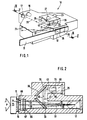
- FIG. 1 shows a schematic, highly simplified perspective illustration of an optical unit 10 of a preferred embodiment of a device according to the invention.
- the test strip 11 which is a double-field test strip, the test fields 13 and 15 of which are to be evaluated. 1 primarily serves to illustrate the beam path in the optical unit in principle. Details can be found in Figures 2 to 4.
- the optical unit shown has two completely separate measuring devices for the two test fields 13 and 15 and therefore has two light-emitting diodes 17 and 19, two measuring receivers 21 and 23 and two reference receivers 25 and 27. For the sake of clarity, only one of the beam paths is marked with arrows dashed lines.
- the central beam of the beam of rays emanating from the light-emitting diode 17 is designated by 29 insofar as it is also the central beam of the sample beam and the reference beam when it leaves the light-emitting diode. It passes through the beam splitter 33 at the dividing point 31 and strikes approximately in the middle 35 of the test field. The second part of the central beam of the sample beam, which is no longer common to the reference beam, is designated by 30.
- the light beam which is diffusely reflected from the test field 13 to the measuring receiver 21 is denoted by 37.
- the light path from the light emitting diode 17 to the measuring receiver 21 forms the measuring channel as a whole.
- the beam splitter 33 reflects a portion of the beam bundle used for sample illumination upwards against the second beam splitter 39.
- the central beam of this part of the beam bundle used for the reference measurement is designated 41.
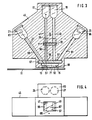
- FIG. 2 is a section in the plane defined by the central beam of the beam bundle 29, 41, 43 used for the reference measurement. This plane runs perpendicular to the surface of the test strip 11 in the measuring position, wherein it intersects it approximately in the middle of the test field to be measured (here the test field 13) perpendicular to its longitudinal extent.
- FIG. 3 is a section through the plane in which the central beam of the beam bundle 30 used for sample illumination and the central beam (“detection axis •) of the light 37 diffusely reflected from the sample surface to the measurement receiver 21 lie. This plane also runs approximately through the center of the test field to be measured and perpendicular to the surface of the test strip in the measuring position, but it extends in its longitudinal direction and therefore runs perpendicular to the previously described plane.
- the 3 shows two light wells 47 and 49 in a housing block 45, through which the light emitted by the light-emitting diodes 17 and 19 falls perpendicularly onto the sample surfaces 51 and 53, each of which is part of the surfaces of the test fields 13 and 15 of the test strip 11 are.
- the beam bundles of both measuring channels used for sample illumination penetrate the first beam splitter 33, which can only be seen in cross section in FIG. 3.
- the beam splitter is a glass or plastic plate common to both measuring channels. However, this is only for technical reasons.
- the two parallel light wells 47 and 49 are separated by the web 73, as can be seen in FIG. 3, so that the component 33 optically forms a separate beam splitter for the two measuring channels 13 and 15 assigned to the test panel.
- the central beam of the beam 30 used for sample illumination coincides with that of the beam used for the reference measurement. Both are in this part designated by reference numeral 29.
- the beam bundle used for sample illumination is limited at the test strip end 55, 57 of the light wells 47 and 49 by their width. This therefore forms the aperture diaphragm of the beam of rays used for sample illumination. You can see that. only a narrow section of the light leaving the LEDs is used for sample illumination.
- the light diffusely reflected by the sample surface 51 and 53 passes through light wells 59 and 61 to the measuring receivers 21 and 23. It can be seen that the light wells 59, 61 are wider than the light wells 47 and 49. This ensures that total of the illuminated part of the surface of the test sensors 13 and 15, i.e. H. Diffuse reflected light is detected by the sample surfaces 51 and 53 in the direction of the light-sensitive surfaces 63 and 65 of the measuring receivers 21 and 23. If the light wells 59 and 61 were too narrow, there would be the danger that they would block out part of the light to be detected by the measuring receivers 21 and 23. This could have the consequence that a slight change in the positioning of the test strip in the direction of the light-emitting diodes 17 and 19 could result in a change in the signal.
- optical window 67 At the end of the light wells 47, 49, 59 and 61 on the test strip side there is an optical window 67. It can be seen that the optical window 67 is set back relative to the measuring opening 69 and leaves a recess 71 free. It is thereby achieved that the optical window 67, which is provided to avoid contamination of the components of the optical unit 10, cannot itself be contaminated by the measuring fields 13 and 15, which are indeed wetted with a sample liquid, in particular blood.
- the arrangement of the optical window 67 directly at the ends 55 and 57 of the light wells 47 and 49 ensures that no light reflected at the optical window 67 can reach the measuring receivers 21 and 23.
- the web 73 separating the two light wells 47 and 49 ends at the optics window 67.
- the recess 71 between the optics window 67 and the measurement opening 69 there is no separation between the two measurement channels of the test fields 13 and 15.
- the light-emitting diodes and measuring receivers of a measuring channel are controlled by the measuring electronics one after the other.
- this electronic separation of the two measuring channels is preferred, the person skilled in the art can also readily obtain a solution in which an optical separation of the two measuring channels is also achieved in the recess 71 by means of a suitable aperture.
- All components, in particular the light-emitting diodes, the photoreceivers and the beam splitter (s) are precisely fitted into corresponding recesses in the housing block 45, so that their position does not change over long periods of time when the device is used, and thus the geometry of the beam paths is maintained over the long term remains.
- test fields 13 and 15 are pressed against the measuring opening 69 by a pressure device 75, which is shown schematically in FIG. 2 and ensures that the contact pressure, which is symbolized by the arrow P in FIG. 2, is sufficiently accurate under all measuring conditions remains constant.
- a pressure device 75 which is shown schematically in FIG. 2 and ensures that the contact pressure, which is symbolized by the arrow P in FIG. 2, is sufficiently accurate under all measuring conditions remains constant.
- the beam bundle of one measuring channel used for the sample illumination which emanates from the light-emitting diode 17, penetrates the first beam splitter 33 and the optical window and falls on the sample surface 51 at the measuring opening 69, is in its extension transverse to the longitudinal direction of the test strip 11 in FIG. 2 detect.
- the marginal rays are designated 77. It can be seen that the beam bundle used for sample illumination in the drawing plane of FIG. 2 is considerably wider than in the drawing plane of FIG. 3.
- the rectangular shape can be seen particularly well from FIG. 4, in which the ends 55 and 57 of the test strip Light wells 47 and 49, which limit the beam used for sample illumination, are shown.
- the solid angle corresponding to this beam can be calculated in a known manner from the area of the rectangle illuminating the test field 13 and the distance of the test field from the light source.
- the rectangular shape of the light well was chosen in order to adapt the beam of rays used for sample illumination to the shape of the usable area of the test fields 13 and 15. It can also be seen from the figures that the sample areas 51 and 53 illuminated by the light emitting diodes 17 and 19, respectively, only make up a relatively small part of the surfaces of the test fields 13 and 15. This is necessary because the edge areas of the test fields can be less homogeneous and are therefore less suitable for evaluation. However, it also has the consequence that only a part of about 1.5 x 4 mm of the entire test field area of, for example, 3 x 6 mm is available for the evaluation.
- the reference receiver 25 is located in an attachment 80 of the housing block 45.
- the beam of rays used for the reference measurement the edge rays of which are identified by the reference numerals 81, 83 and 85, reaches it via the two beam splitter plates 33 and 39 to the reference receiver 25.
- the solid angle used by the reference beam of the light emitted by the light-emitting diode 17 is determined by the size of the photosensitive surface 79 of the reference receiver 25. This is shown enlarged in the figure for the sake of clarity. In the case of a photodiode which is preferably used as a reference receiver, the light-sensitive area is only about 1 mm ⁇ 1 mm in size. 2 clearly shows that the solid angle of the reference beam lies entirely in the solid angle of the sample beam. This applies not only in the plane of FIG. 2, but also in the plane of FIG. 3, in which, for the sake of clarity, the corresponding marginal rays have not been shown.
- plane-parallel plates made of a transparent material such as glass or plastic are preferably used as beam splitters.
- a proportion of approximately 4 to 5% of the incident light is reflected vertically upward on the first beam splitter 33 by the beam splitter arranged at an angle of 45%.
- the second beam splitter is practically used as a mirror which serves for additional beam attenuation. Practical tests have shown that the preferred division ratio mentioned above can be easily achieved when using a second beam splitter, the two deflections of the beam having the additional advantage that it leads to a particularly small construction.
- the light penetrating the second beam splitter 39 is essentially absorbed on the rear side by the largely absorbing adjacent surface 90.
- the degree of beam weakening that can be achieved by the second beam splitter can advantageously be set by making the surface 90 more or less absorbent.
Landscapes
- Health & Medical Sciences (AREA)
- Life Sciences & Earth Sciences (AREA)
- Biochemistry (AREA)
- Physics & Mathematics (AREA)
- Chemical & Material Sciences (AREA)
- Analytical Chemistry (AREA)
- General Health & Medical Sciences (AREA)
- General Physics & Mathematics (AREA)
- Immunology (AREA)
- Pathology (AREA)
- Molecular Biology (AREA)
- Investigating Or Analysing Materials By Optical Means (AREA)
- Analysing Materials By The Use Of Radiation (AREA)
Claims (15)
Priority Applications (1)
| Application Number | Priority Date | Filing Date | Title |
|---|---|---|---|
| AT85102028T ATE34044T1 (de) | 1984-03-02 | 1985-02-23 | Geraet zur bestimmung des diffusen reflexionsvermoegens einer probenflaeche kleiner abmessungen. |
Applications Claiming Priority (2)
| Application Number | Priority Date | Filing Date | Title |
|---|---|---|---|
| DE3407754 | 1984-03-02 | ||
| DE19843407754 DE3407754A1 (de) | 1984-03-02 | 1984-03-02 | Geraet zur bestimmung des diffusen reflexionsvermoegens einer probenflaeche kleiner abmessungen |
Publications (3)
| Publication Number | Publication Date |
|---|---|
| EP0154875A2 EP0154875A2 (fr) | 1985-09-18 |
| EP0154875A3 EP0154875A3 (en) | 1986-03-12 |
| EP0154875B1 true EP0154875B1 (fr) | 1988-05-04 |
Family
ID=6229432
Family Applications (1)
| Application Number | Title | Priority Date | Filing Date |
|---|---|---|---|
| EP85102028A Expired EP0154875B1 (fr) | 1984-03-02 | 1985-02-23 | Appareil pour la détermination de la réflectivité diffuse d'un surface échantillon de petites dimensions |
Country Status (10)
| Country | Link |
|---|---|
| US (1) | US4676653A (fr) |
| EP (1) | EP0154875B1 (fr) |
| JP (1) | JPS60205239A (fr) |
| KR (1) | KR850006894A (fr) |
| AT (1) | ATE34044T1 (fr) |
| AU (1) | AU556377B2 (fr) |
| CA (1) | CA1224640A (fr) |
| DE (2) | DE3407754A1 (fr) |
| ES (1) | ES8606643A1 (fr) |
| FI (1) | FI850840L (fr) |
Families Citing this family (77)
| Publication number | Priority date | Publication date | Assignee | Title |
|---|---|---|---|---|
| DE3543416A1 (de) * | 1985-12-09 | 1987-06-11 | Hoechst Ag | Verfahren zum photometrischen auswerten von farbfeldern auf teststreifen |
| US4737369A (en) * | 1986-03-11 | 1988-04-12 | Ajinomoto General Foods, Inc. | Fat-containing powder product quickly dispersible in cold water and process for preparing the same |
| EP0358818B1 (fr) * | 1988-09-12 | 1992-04-22 | Moshe Golberstein | Instrument de photométrie de réflexion |
| US4770536A (en) * | 1986-12-04 | 1988-09-13 | Moshe Golberstein | Reflective photometry instrument |
| DE3701721A1 (de) * | 1987-01-22 | 1988-08-04 | Zeiss Carl Fa | Remissionsmessgeraet zur beruehrungslosen messung |
| US5028139A (en) * | 1987-07-16 | 1991-07-02 | Miles Inc. | Readhead for reflectance measurement of distant samples |
| DE8716270U1 (fr) * | 1987-12-09 | 1988-02-18 | Lre Relais + Elektronik Gmbh, 8000 Muenchen, De | |
| US4890926A (en) * | 1987-12-21 | 1990-01-02 | Miles Inc. | Reflectance photometer |
| DE3914037A1 (de) * | 1989-04-28 | 1990-10-31 | Boehringer Mannheim Gmbh | Testtraegeranalysegeraet |
| US4945250A (en) * | 1989-07-12 | 1990-07-31 | Pb Diagnostic Systems, Inc. | Optical read head for immunoassay instrument |
| US5113082A (en) * | 1990-09-11 | 1992-05-12 | Moshe Golberstein | Electro-optical instrument with self-contained photometer |
| US5162874A (en) * | 1990-12-24 | 1992-11-10 | Xerox Corporation | Electrophotographic machine having a method and apparatus for measuring toner density by using diffuse electromagnetic energy |
| US5053822A (en) * | 1990-12-24 | 1991-10-01 | Xerox Corporation | Densitometer for measuring marking particle density on a photoreceptor having a compensation ratio which adjusts for changing environmental conditions and variability between machines |
| US5246858A (en) * | 1991-02-27 | 1993-09-21 | Boehringer Mannheim Corporation | Apparatus and method for analyzing a body fluid |
| JP3118552B2 (ja) * | 1991-02-27 | 2000-12-18 | ロッシュ ダイアグノスティックス コーポレイション | 体液の分析装置及び方法 |
| US5232668A (en) * | 1991-02-27 | 1993-08-03 | Boehringer Mannheim Corporation | Test strip holding and reading mechanism for a meter |
| US5371687A (en) * | 1992-11-20 | 1994-12-06 | Boehringer Mannheim Corporation | Glucose test data acquisition and management system |
| US7141212B2 (en) * | 1993-11-12 | 2006-11-28 | Inverness Medical Switzerland Gmbh | Reading devices and assay devices for use therewith |
| US5597532A (en) * | 1994-10-20 | 1997-01-28 | Connolly; James | Apparatus for determining substances contained in a body fluid |
| AU676270B1 (en) * | 1995-09-05 | 1997-03-06 | Bayer Corporation | Diffused light reflectance readhead |
| JP3984651B2 (ja) * | 1996-04-30 | 2007-10-03 | メトリカ・インコーポレーテッド | 反射光線の測定方法及びその装置 |
| DE19639227B4 (de) * | 1996-09-24 | 2006-11-23 | Lre Technology Partner Gmbh | Verfahren und Vorrichtung zur Blutzuckermessung |
| US7390667B2 (en) | 1997-12-22 | 2008-06-24 | Roche Diagnostics Operations, Inc. | System and method for analyte measurement using AC phase angle measurements |
| US8071384B2 (en) | 1997-12-22 | 2011-12-06 | Roche Diagnostics Operations, Inc. | Control and calibration solutions and methods for their use |
| US7494816B2 (en) | 1997-12-22 | 2009-02-24 | Roche Diagnostic Operations, Inc. | System and method for determining a temperature during analyte measurement |
| US7407811B2 (en) | 1997-12-22 | 2008-08-05 | Roche Diagnostics Operations, Inc. | System and method for analyte measurement using AC excitation |
| DE19757416A1 (de) * | 1997-12-23 | 1999-07-01 | Siemens Ag | Verfahren und Vorrichtung zum Erkennen von Papierarten und Verwendung des Verfahrens bzw. der Vorrichtung |
| WO1999035487A1 (fr) * | 1998-01-06 | 1999-07-15 | Skyline Venture Partners, L.P. | Procedes et appareil permettant l'analyse exacte des composants d'un fluide corporel |
| US6394952B1 (en) | 1998-02-03 | 2002-05-28 | Adeza Biomedical Corporation | Point of care diagnostic systems |
| US6267722B1 (en) | 1998-02-03 | 2001-07-31 | Adeza Biomedical Corporation | Point of care diagnostic systems |
| JP2002502980A (ja) | 1998-02-10 | 2002-01-29 | イーワイ ラボラトリーズ インコーポレイテッド | 試料ホルダ起伏形状を補償し且つシステム・ノイズのロック除去を行う反射測定システム |
| USD432244S (en) * | 1998-04-20 | 2000-10-17 | Adeza Biomedical Corporation | Device for encasing an assay test strip |
| USD434153S (en) * | 1998-04-20 | 2000-11-21 | Adeza Biomedical Corporation | Point of care analyte detector system |
| GB2339615B (en) * | 1998-07-14 | 2001-02-07 | Cozart Bioscience Ltd | Screening device and method of screening an immunoassay test |
| DE19930688A1 (de) * | 1999-07-02 | 2001-01-04 | Byk Gardner Gmbh | Vorrichtung und Verfahren zur Bestimmung der Qualität von Oberflächen |
| US6458326B1 (en) | 1999-11-24 | 2002-10-01 | Home Diagnostics, Inc. | Protective test strip platform |
| US6249308B1 (en) * | 2000-01-25 | 2001-06-19 | Eastman Kodak Company | Method of controlling peak power of a radiant energy emitting system |
| US6541266B2 (en) | 2001-02-28 | 2003-04-01 | Home Diagnostics, Inc. | Method for determining concentration of an analyte in a test strip |
| US6525330B2 (en) | 2001-02-28 | 2003-02-25 | Home Diagnostics, Inc. | Method of strip insertion detection |
| US6562625B2 (en) | 2001-02-28 | 2003-05-13 | Home Diagnostics, Inc. | Distinguishing test types through spectral analysis |
| DE10149780B4 (de) * | 2001-10-09 | 2019-09-05 | Byk Gardner Gmbh | Einrichtung zur Beleuchtung einer Messfläche und Vorrichtung und Verfahren zur Bestimmung der visuellen Eigenschaften von Körpern |
| DE10156804B4 (de) * | 2001-11-20 | 2011-03-17 | Quidel Corp., San Diego | Optische Meßvorrichtung für Teststreifen |
| US7623240B2 (en) * | 2001-11-20 | 2009-11-24 | Iris Deutschland Gmbh | Optical measuring device for test strips |
| JP2004170217A (ja) * | 2002-11-19 | 2004-06-17 | Hamamatsu Photonics Kk | 呈色測定装置 |
| US7173705B2 (en) * | 2003-02-26 | 2007-02-06 | Hamamatsu Photonics K.K. | Measuring device for immunochromatography test piece |
| US7173704B2 (en) * | 2003-02-26 | 2007-02-06 | Hamamatsu Photonics K.K. | Measuring device for immunochromatography test piece and light source device |
| US7239394B2 (en) | 2003-06-04 | 2007-07-03 | Inverness Medical Switzerland Gmbh | Early determination of assay results |
| US7315378B2 (en) * | 2003-06-04 | 2008-01-01 | Inverness Medical Switzerland Gmbh | Optical arrangement for assay reading device |
| US7317532B2 (en) * | 2003-06-04 | 2008-01-08 | Inverness Medical Switzerland Gmbh | Flow sensing for determination of assay results |
| US7604721B2 (en) | 2003-06-20 | 2009-10-20 | Roche Diagnostics Operations, Inc. | System and method for coding information on a biosensor test strip |
| US7645421B2 (en) | 2003-06-20 | 2010-01-12 | Roche Diagnostics Operations, Inc. | System and method for coding information on a biosensor test strip |
| US8058077B2 (en) | 2003-06-20 | 2011-11-15 | Roche Diagnostics Operations, Inc. | Method for coding information on a biosensor test strip |
| US7488601B2 (en) | 2003-06-20 | 2009-02-10 | Roche Diagnostic Operations, Inc. | System and method for determining an abused sensor during analyte measurement |
| US7645373B2 (en) | 2003-06-20 | 2010-01-12 | Roche Diagnostic Operations, Inc. | System and method for coding information on a biosensor test strip |
| US7718439B2 (en) | 2003-06-20 | 2010-05-18 | Roche Diagnostics Operations, Inc. | System and method for coding information on a biosensor test strip |
| US8206565B2 (en) | 2003-06-20 | 2012-06-26 | Roche Diagnostics Operation, Inc. | System and method for coding information on a biosensor test strip |
| US7597793B2 (en) | 2003-06-20 | 2009-10-06 | Roche Operations Ltd. | System and method for analyte measurement employing maximum dosing time delay |
| US7452457B2 (en) | 2003-06-20 | 2008-11-18 | Roche Diagnostics Operations, Inc. | System and method for analyte measurement using dose sufficiency electrodes |
| US8148164B2 (en) | 2003-06-20 | 2012-04-03 | Roche Diagnostics Operations, Inc. | System and method for determining the concentration of an analyte in a sample fluid |
| WO2005078118A1 (fr) | 2004-02-06 | 2005-08-25 | Bayer Healthcare Llc | Especes oxydables servant de reference interne a des biocapteurs, et procede d'utilisation |
| US7339673B2 (en) * | 2004-03-05 | 2008-03-04 | Siemens Healthcare Diagnostics Inc. | Miniature optical readhead for optical diagnostic device |
| CN1950694B (zh) * | 2004-05-06 | 2010-04-14 | 松下电器产业株式会社 | 传感器、测量装置以及测量方法 |
| US7569126B2 (en) | 2004-06-18 | 2009-08-04 | Roche Diagnostics Operations, Inc. | System and method for quality assurance of a biosensor test strip |
| US7556723B2 (en) | 2004-06-18 | 2009-07-07 | Roche Diagnostics Operations, Inc. | Electrode design for biosensor |
| US7763454B2 (en) * | 2004-07-09 | 2010-07-27 | Church & Dwight Co., Inc. | Electronic analyte assaying device |
| MX2008000836A (es) * | 2005-07-20 | 2008-03-26 | Bayer Healthcare Llc | Amperimetria regulada. |
| WO2007022213A2 (fr) * | 2005-08-15 | 2007-02-22 | X-Rite, Incorporated | Instrument optique amélioré et composants idoines |
| DE102005043834A1 (de) * | 2005-09-13 | 2007-03-22 | Eppendorf Ag | Vorrichtung zur Durchführung von Real-Time PCR-Reaktionen |
| ES2716136T3 (es) | 2005-09-30 | 2019-06-10 | Ascensia Diabetes Care Holdings Ag | Voltamperometría controlada |
| EP2069776B1 (fr) * | 2006-08-08 | 2017-12-13 | Hach Company | Procédé et appareil pour analyser des solutions |
| US20080267446A1 (en) * | 2007-04-18 | 2008-10-30 | Dale Capewell | Chemistry strip reader and method |
| US8150115B2 (en) * | 2007-04-18 | 2012-04-03 | Iris International, Inc. | Chemistry strip reader and method |
| WO2009076302A1 (fr) | 2007-12-10 | 2009-06-18 | Bayer Healthcare Llc | Marqueurs de contrôle pour la détection automatique d'une solution de contrôle et procédés d'utilisation |
| US20110122411A1 (en) * | 2008-06-20 | 2011-05-26 | 77 Elektronika Mvszeripari Kft. | Optical measuring unit and method for carrying out a reflective measurement |
| CN102401796B (zh) * | 2010-09-09 | 2017-02-01 | 艾博生物医药(杭州)有限公司 | 一种读取测试载体上化验结果的设备 |
| US10048197B2 (en) * | 2015-04-28 | 2018-08-14 | Taiwan Biophotonic Corporation | Optical measurement device and optical measurement method |
| WO2017145789A1 (fr) * | 2016-02-26 | 2017-08-31 | ソニー株式会社 | Dispositif de positionnement, dispositif de communication et système de positionnement |
Family Cites Families (11)
| Publication number | Priority date | Publication date | Assignee | Title |
|---|---|---|---|---|
| US2382439A (en) * | 1941-06-19 | 1945-08-14 | Hercules Powder Co Ltd | Color grading apparatus and method |
| US3645634A (en) * | 1970-05-14 | 1972-02-29 | Rca Corp | Apparatus for measuring light transmission of a semitransparent membrane |
| US3709612A (en) * | 1971-03-10 | 1973-01-09 | Miles Lab | Apparatus for measuring reflected light under stabilized light source conditions |
| US4040747A (en) * | 1972-08-24 | 1977-08-09 | Neotec Corporation | Optical analyzer for agricultural products |
| US4029419A (en) * | 1975-10-10 | 1977-06-14 | International Business Machines Corporation | Textile color analyzer calibration |
| US4147430A (en) * | 1976-11-10 | 1979-04-03 | Ardac, Inc. | Secondary detection system for security validation |
| DE3138879A1 (de) * | 1981-09-30 | 1983-04-14 | Boehringer Mannheim Gmbh, 6800 Mannheim | Verfahren zur erfassung photometrischer signale und anordnung zur durchfuehrung des verfahrens |
| DE3138878A1 (de) * | 1981-09-30 | 1983-04-14 | Boehringer Mannheim Gmbh, 6800 Mannheim | Messeinrichtung, insbesondere ulbricht'sche kugel |
| CA1174076A (fr) * | 1981-12-02 | 1984-09-11 | Eastman Kodak Company | Radiometre normalise, et methode de mesure des composantes d'un melange |
| US4518259A (en) * | 1982-07-26 | 1985-05-21 | Eastman Kodak Company | Light guide reflectometer |
| US4552458A (en) * | 1983-10-11 | 1985-11-12 | Eastman Kodak Company | Compact reflectometer |
-
1984
- 1984-03-02 DE DE19843407754 patent/DE3407754A1/de not_active Withdrawn
- 1984-08-27 US US06/644,870 patent/US4676653A/en not_active Expired - Lifetime
-
1985
- 1985-02-23 DE DE8585102028T patent/DE3562534D1/de not_active Expired
- 1985-02-23 AT AT85102028T patent/ATE34044T1/de not_active IP Right Cessation
- 1985-02-23 EP EP85102028A patent/EP0154875B1/fr not_active Expired
- 1985-02-25 AU AU39111/85A patent/AU556377B2/en not_active Ceased
- 1985-02-27 CA CA000475302A patent/CA1224640A/fr not_active Expired
- 1985-02-27 ES ES540745A patent/ES8606643A1/es not_active Expired
- 1985-02-28 KR KR1019850001276A patent/KR850006894A/ko not_active Application Discontinuation
- 1985-03-01 FI FI850840A patent/FI850840L/fi not_active Application Discontinuation
- 1985-03-01 JP JP60038967A patent/JPS60205239A/ja active Pending
Also Published As
| Publication number | Publication date |
|---|---|
| EP0154875A2 (fr) | 1985-09-18 |
| FI850840L (fi) | 1985-09-03 |
| EP0154875A3 (en) | 1986-03-12 |
| FI850840A0 (fi) | 1985-03-01 |
| AU556377B2 (en) | 1986-10-30 |
| ES8606643A1 (es) | 1986-04-16 |
| KR850006894A (ko) | 1985-10-21 |
| AU3911185A (en) | 1985-09-05 |
| ATE34044T1 (de) | 1988-05-15 |
| DE3562534D1 (en) | 1988-06-09 |
| US4676653A (en) | 1987-06-30 |
| CA1224640A (fr) | 1987-07-28 |
| ES540745A0 (es) | 1986-04-16 |
| DE3407754A1 (de) | 1985-09-12 |
| JPS60205239A (ja) | 1985-10-16 |
Similar Documents
| Publication | Publication Date | Title |
|---|---|---|
| EP0154875B1 (fr) | Appareil pour la détermination de la réflectivité diffuse d'un surface échantillon de petites dimensions | |
| EP1117989B1 (fr) | Procede d'evaluation photometrique d'elements de test | |
| AT404513B (de) | Verfahren und messanordnung zur optischen bestimmung der totalen hämoglobinkonzentration | |
| DE2739585C2 (de) | Spektrophotometer | |
| DE2049716C3 (de) | Verfahren und Vorrichtung zur Absorptionsmessung im Blut | |
| DE2902776C2 (fr) | ||
| EP2221608B1 (fr) | Procédé de test destiné à examiner un liquide corporel | |
| DE19825518C2 (de) | Vorrichtung zur Messung von Parameteränderungen an lichtdurchlässigen Objekten | |
| DE10008517C2 (de) | Optisches Meßsystem | |
| EP0819943A2 (fr) | Système d'analyse avec moyens de détection d'un dosage insuffisant | |
| EP1921441B1 (fr) | Appareil d'analyse d'un élément de test d'échantillon et système d'analyse | |
| DE102008057115B4 (de) | Verfahren zur quantitativen Bestimmung der Konzentration von Fluorophoren einer Substanz in einer Probe und Vorrichtung zu seiner Durchführung | |
| DD140290A5 (de) | Kombiniertes goniophotometer und reflektometer(gonioreflektometer)zur beurteilung des oberflaechenglanzvermoegens | |
| DE19532877A1 (de) | Vorrichtung zur linienförmigen Beleuchtung von Blattgut, wie z. B. Banknoten oder Wertpapiere | |
| DE102013219830B4 (de) | Optische Vorrichtung zur Reflexionsmessung unter diffuser Beleuchtung und Verfahren zum Optimieren einer solchen, sowie Verwendung der Vorrichtung | |
| EP2270516A2 (fr) | Système d'analyse avec moyens de détection d'un dosage insuffisant | |
| EP0394909B1 (fr) | Procédé d'illumination diffuse d'une aire de mesure dans un analyseur pour support d'essai | |
| EP0043522B1 (fr) | Réfractomètre | |
| DE19816359A1 (de) | Fasersensor zum Erkennen von Oberflächenstrukturen | |
| EP0548027A2 (fr) | Appareil pour l'analyse spectrométrique | |
| EP3504537B1 (fr) | Dispositif pour mesurer la fluorescence utilisant une carte imprimée avec source de lumière et capteur attachés, la carte imprimée comprenant une fissure pour supprimer la conduction de lumière | |
| DE3428435A1 (de) | Rauheitssonde | |
| DE3844651C2 (fr) | ||
| EP2825868B1 (fr) | Système de test et procédé de contrôle de l'orientation d'une bandelette de test | |
| DD203632A1 (de) | Schnellverfahren und einrichtung zur fotometrischen blutuntersuchung |
Legal Events
| Date | Code | Title | Description |
|---|---|---|---|
| PUAI | Public reference made under article 153(3) epc to a published international application that has entered the european phase |
Free format text: ORIGINAL CODE: 0009012 |
|
| 17P | Request for examination filed |
Effective date: 19850223 |
|
| AK | Designated contracting states |
Designated state(s): AT BE CH DE FR GB IT LI LU NL SE |
|
| PUAL | Search report despatched |
Free format text: ORIGINAL CODE: 0009013 |
|
| AK | Designated contracting states |
Kind code of ref document: A3 Designated state(s): AT BE CH DE FR GB IT LI LU NL SE |
|
| 17Q | First examination report despatched |
Effective date: 19870714 |
|
| GRAA | (expected) grant |
Free format text: ORIGINAL CODE: 0009210 |
|
| AK | Designated contracting states |
Kind code of ref document: B1 Designated state(s): AT BE CH DE FR GB IT LI LU NL SE |
|
| REF | Corresponds to: |
Ref document number: 34044 Country of ref document: AT Date of ref document: 19880515 Kind code of ref document: T |
|
| ITF | It: translation for a ep patent filed |
Owner name: ING. C. GREGORJ S.P.A. |
|
| REF | Corresponds to: |
Ref document number: 3562534 Country of ref document: DE Date of ref document: 19880609 |
|
| ET | Fr: translation filed | ||
| GBT | Gb: translation of ep patent filed (gb section 77(6)(a)/1977) | ||
| PLBE | No opposition filed within time limit |
Free format text: ORIGINAL CODE: 0009261 |
|
| STAA | Information on the status of an ep patent application or granted ep patent |
Free format text: STATUS: NO OPPOSITION FILED WITHIN TIME LIMIT |
|
| 26N | No opposition filed | ||
| ITTA | It: last paid annual fee | ||
| EPTA | Lu: last paid annual fee | ||
| EAL | Se: european patent in force in sweden |
Ref document number: 85102028.9 |
|
| PGFP | Annual fee paid to national office [announced via postgrant information from national office to epo] |
Ref country code: SE Payment date: 20010206 Year of fee payment: 17 |
|
| PGFP | Annual fee paid to national office [announced via postgrant information from national office to epo] |
Ref country code: FR Payment date: 20010213 Year of fee payment: 17 Ref country code: AT Payment date: 20010213 Year of fee payment: 17 |
|
| PGFP | Annual fee paid to national office [announced via postgrant information from national office to epo] |
Ref country code: GB Payment date: 20010221 Year of fee payment: 17 |
|
| PGFP | Annual fee paid to national office [announced via postgrant information from national office to epo] |
Ref country code: LU Payment date: 20010227 Year of fee payment: 17 |
|
| PGFP | Annual fee paid to national office [announced via postgrant information from national office to epo] |
Ref country code: NL Payment date: 20010228 Year of fee payment: 17 |
|
| PGFP | Annual fee paid to national office [announced via postgrant information from national office to epo] |
Ref country code: CH Payment date: 20010302 Year of fee payment: 17 |
|
| PGFP | Annual fee paid to national office [announced via postgrant information from national office to epo] |
Ref country code: BE Payment date: 20010420 Year of fee payment: 17 |
|
| REG | Reference to a national code |
Ref country code: GB Ref legal event code: IF02 |
|
| PG25 | Lapsed in a contracting state [announced via postgrant information from national office to epo] |
Ref country code: LU Free format text: LAPSE BECAUSE OF NON-PAYMENT OF DUE FEES Effective date: 20020223 Ref country code: GB Free format text: LAPSE BECAUSE OF NON-PAYMENT OF DUE FEES Effective date: 20020223 Ref country code: AT Free format text: LAPSE BECAUSE OF NON-PAYMENT OF DUE FEES Effective date: 20020223 |
|
| PG25 | Lapsed in a contracting state [announced via postgrant information from national office to epo] |
Ref country code: SE Free format text: LAPSE BECAUSE OF NON-PAYMENT OF DUE FEES Effective date: 20020224 |
|
| PG25 | Lapsed in a contracting state [announced via postgrant information from national office to epo] |
Ref country code: LI Free format text: LAPSE BECAUSE OF NON-PAYMENT OF DUE FEES Effective date: 20020228 Ref country code: CH Free format text: LAPSE BECAUSE OF NON-PAYMENT OF DUE FEES Effective date: 20020228 Ref country code: BE Free format text: LAPSE BECAUSE OF NON-PAYMENT OF DUE FEES Effective date: 20020228 |
|
| BERE | Be: lapsed |
Owner name: BOEHRINGER MANNHEIM G.M.B.H. Effective date: 20020228 |
|
| PG25 | Lapsed in a contracting state [announced via postgrant information from national office to epo] |
Ref country code: NL Free format text: LAPSE BECAUSE OF NON-PAYMENT OF DUE FEES Effective date: 20020901 |
|
| EUG | Se: european patent has lapsed |
Ref document number: 85102028.9 |
|
| REG | Reference to a national code |
Ref country code: CH Ref legal event code: PL |
|
| GBPC | Gb: european patent ceased through non-payment of renewal fee |
Effective date: 20020223 |
|
| PG25 | Lapsed in a contracting state [announced via postgrant information from national office to epo] |
Ref country code: FR Free format text: LAPSE BECAUSE OF NON-PAYMENT OF DUE FEES Effective date: 20021031 |
|
| NLV4 | Nl: lapsed or anulled due to non-payment of the annual fee |
Effective date: 20020901 |
|
| REG | Reference to a national code |
Ref country code: FR Ref legal event code: ST |
|
| PGFP | Annual fee paid to national office [announced via postgrant information from national office to epo] |
Ref country code: DE Payment date: 20030306 Year of fee payment: 19 |
|
| PG25 | Lapsed in a contracting state [announced via postgrant information from national office to epo] |
Ref country code: DE Free format text: LAPSE BECAUSE OF NON-PAYMENT OF DUE FEES Effective date: 20040901 |