EP0807750B1 - Gegassener Kolben mit verstärktem Brennraummulderand - Google Patents
Gegassener Kolben mit verstärktem Brennraummulderand Download PDFInfo
- Publication number
- EP0807750B1 EP0807750B1 EP97303241A EP97303241A EP0807750B1 EP 0807750 B1 EP0807750 B1 EP 0807750B1 EP 97303241 A EP97303241 A EP 97303241A EP 97303241 A EP97303241 A EP 97303241A EP 0807750 B1 EP0807750 B1 EP 0807750B1
- Authority
- EP
- European Patent Office
- Prior art keywords
- piston
- cast
- insert
- combustion bowl
- metal insert
- Prior art date
- Legal status (The legal status is an assumption and is not a legal conclusion. Google has not performed a legal analysis and makes no representation as to the accuracy of the status listed.)
- Expired - Lifetime
Links
Images

Classifications
-
- F—MECHANICAL ENGINEERING; LIGHTING; HEATING; WEAPONS; BLASTING
- F02—COMBUSTION ENGINES; HOT-GAS OR COMBUSTION-PRODUCT ENGINE PLANTS
- F02B—INTERNAL-COMBUSTION PISTON ENGINES; COMBUSTION ENGINES IN GENERAL
- F02B23/00—Other engines characterised by special shape or construction of combustion chambers to improve operation
- F02B23/02—Other engines characterised by special shape or construction of combustion chambers to improve operation with compression ignition
- F02B23/06—Other engines characterised by special shape or construction of combustion chambers to improve operation with compression ignition the combustion space being arranged in working piston
- F02B23/0603—Other engines characterised by special shape or construction of combustion chambers to improve operation with compression ignition the combustion space being arranged in working piston at least part of the interior volume or the wall of the combustion space being made of material different from the surrounding piston part, e.g. combustion space formed within a ceramic part fixed to a metal piston head
-
- B—PERFORMING OPERATIONS; TRANSPORTING
- B22—CASTING; POWDER METALLURGY
- B22D—CASTING OF METALS; CASTING OF OTHER SUBSTANCES BY THE SAME PROCESSES OR DEVICES
- B22D19/00—Casting in, on, or around objects which form part of the product
- B22D19/0009—Cylinders, pistons
- B22D19/0027—Cylinders, pistons pistons
-
- F—MECHANICAL ENGINEERING; LIGHTING; HEATING; WEAPONS; BLASTING
- F02—COMBUSTION ENGINES; HOT-GAS OR COMBUSTION-PRODUCT ENGINE PLANTS
- F02B—INTERNAL-COMBUSTION PISTON ENGINES; COMBUSTION ENGINES IN GENERAL
- F02B23/00—Other engines characterised by special shape or construction of combustion chambers to improve operation
- F02B23/02—Other engines characterised by special shape or construction of combustion chambers to improve operation with compression ignition
- F02B23/06—Other engines characterised by special shape or construction of combustion chambers to improve operation with compression ignition the combustion space being arranged in working piston
- F02B23/0672—Omega-piston bowl, i.e. the combustion space having a central projection pointing towards the cylinder head and the surrounding wall being inclined towards the cylinder center axis
-
- F—MECHANICAL ENGINEERING; LIGHTING; HEATING; WEAPONS; BLASTING
- F02—COMBUSTION ENGINES; HOT-GAS OR COMBUSTION-PRODUCT ENGINE PLANTS
- F02F—CYLINDERS, PISTONS OR CASINGS, FOR COMBUSTION ENGINES; ARRANGEMENTS OF SEALINGS IN COMBUSTION ENGINES
- F02F3/00—Pistons
- F02F3/02—Pistons having means for accommodating or controlling heat expansion
- F02F3/04—Pistons having means for accommodating or controlling heat expansion having expansion-controlling inserts
- F02F3/045—Pistons having means for accommodating or controlling heat expansion having expansion-controlling inserts the inserts being located in the crown
-
- F—MECHANICAL ENGINEERING; LIGHTING; HEATING; WEAPONS; BLASTING
- F02—COMBUSTION ENGINES; HOT-GAS OR COMBUSTION-PRODUCT ENGINE PLANTS
- F02B—INTERNAL-COMBUSTION PISTON ENGINES; COMBUSTION ENGINES IN GENERAL
- F02B3/00—Engines characterised by air compression and subsequent fuel addition
- F02B3/06—Engines characterised by air compression and subsequent fuel addition with compression ignition
-
- F—MECHANICAL ENGINEERING; LIGHTING; HEATING; WEAPONS; BLASTING
- F05—INDEXING SCHEMES RELATING TO ENGINES OR PUMPS IN VARIOUS SUBCLASSES OF CLASSES F01-F04
- F05C—INDEXING SCHEME RELATING TO MATERIALS, MATERIAL PROPERTIES OR MATERIAL CHARACTERISTICS FOR MACHINES, ENGINES OR PUMPS OTHER THAN NON-POSITIVE-DISPLACEMENT MACHINES OR ENGINES
- F05C2201/00—Metals
- F05C2201/02—Light metals
- F05C2201/021—Aluminium
-
- F—MECHANICAL ENGINEERING; LIGHTING; HEATING; WEAPONS; BLASTING
- F05—INDEXING SCHEMES RELATING TO ENGINES OR PUMPS IN VARIOUS SUBCLASSES OF CLASSES F01-F04
- F05C—INDEXING SCHEME RELATING TO MATERIALS, MATERIAL PROPERTIES OR MATERIAL CHARACTERISTICS FOR MACHINES, ENGINES OR PUMPS OTHER THAN NON-POSITIVE-DISPLACEMENT MACHINES OR ENGINES
- F05C2201/00—Metals
- F05C2201/04—Heavy metals
- F05C2201/0433—Iron group; Ferrous alloys, e.g. steel
- F05C2201/0448—Steel
- F05C2201/046—Stainless steel or inox, e.g. 18-8
-
- Y—GENERAL TAGGING OF NEW TECHNOLOGICAL DEVELOPMENTS; GENERAL TAGGING OF CROSS-SECTIONAL TECHNOLOGIES SPANNING OVER SEVERAL SECTIONS OF THE IPC; TECHNICAL SUBJECTS COVERED BY FORMER USPC CROSS-REFERENCE ART COLLECTIONS [XRACs] AND DIGESTS
- Y02—TECHNOLOGIES OR APPLICATIONS FOR MITIGATION OR ADAPTATION AGAINST CLIMATE CHANGE
- Y02T—CLIMATE CHANGE MITIGATION TECHNOLOGIES RELATED TO TRANSPORTATION
- Y02T10/00—Road transport of goods or passengers
- Y02T10/10—Internal combustion engine [ICE] based vehicles
- Y02T10/12—Improving ICE efficiencies
-
- Y—GENERAL TAGGING OF NEW TECHNOLOGICAL DEVELOPMENTS; GENERAL TAGGING OF CROSS-SECTIONAL TECHNOLOGIES SPANNING OVER SEVERAL SECTIONS OF THE IPC; TECHNICAL SUBJECTS COVERED BY FORMER USPC CROSS-REFERENCE ART COLLECTIONS [XRACs] AND DIGESTS
- Y10—TECHNICAL SUBJECTS COVERED BY FORMER USPC
- Y10T—TECHNICAL SUBJECTS COVERED BY FORMER US CLASSIFICATION
- Y10T29/00—Metal working
- Y10T29/49—Method of mechanical manufacture
- Y10T29/49229—Prime mover or fluid pump making
- Y10T29/49249—Piston making
- Y10T29/49256—Piston making with assembly or composite article making
Definitions
- the present invention relates to pistons for internal combustion engines. More particularly, the present invention is directed to cast aluminum pistons which include reinforced combustion bowl edges.
- Pistons used in internal combustion engines, and particularly in medium range diesel engines are generally of one of three designs: gravity cast aluminum pistons, squeeze-formed aluminum/metal matrix composite pistons, and two-piece steel crown/aluminum skirt articulated pistons. There are fairly well defined levels of specific power output which each of these design options can tolerate. Cost varies greatly between the three designs, with gravity cast pistons being the most economical to manufacture.
- Pistons encounter extreme thermal conditions and mechanical forces which together subject certain portions of the pistons to stress that can lead to deterioration and failure.
- efforts have been taken to reinforce and/or thermally insulate portions of cast pistons so that they are more durable and have a longer service life.
- Such efforts include the design of a variety of insert structures which provide thermal barriers and/or internal structural supports. Examples of insert structures used in cast pistons are found in U.S. Patent Nos.
- FR-A- 2354451 discloses cast pistons with
- the present invention provides a cast piston having a reinforced combustion bowl edge which includes an undercut structure that improves combustion, as defined in the independent claims.
- the present invention is directed to cast pistons for internal combustion engines. More particularly, the present invention is directed to cast aluminum pistons which can be made utilizing either a pressure casting process or, more preferably, a gravity casting process.
- the cast pistons of the present invention include a combustion bowl formed in the head thereof.
- An insert is provided around the upper rim of the combustion bowl at the crown of the piston. The insert defines the upper portion of the combustion bowl and reinforces the surrounding crown portion of the piston.
- the insert used in the present invention is preferably made of a material which has similar thermal expansion characteristics as the material from which the crown of the piston is made.
- the insert can be a sintered powder stainless steel insert when used in an aluminum cast piston.
- the cast piston of the present invention is able to provide improved combustion characteristics.
- the edge of the combustion bowl as defined by the insert can be undercut in a "re-entrant" fashion, i.e., in a manner which causes a combustible gaseous fuel to be contained in the combustion bowl before ignition thereof.
- the insert of the present invention was designed to improve the combustion efficiency of cast pistons and accommodate an undercut shape which can strengthen such pistons.
- the insert is designed to be positioned in a piston casting mold in which the piston is cast in a head-up manner.
- the insert can be provided with structural features which can be used to grasp and position the insert into a casting mold.
- the insert of the present invention is designed to be mechanically secured in a cast piston.
- the insert is provided with structural elements which extend into the cast piston head and resist rotational forces and lifting forces. Such rotational and lifting forces are applied to the insert during a machining process.
- a cast piston according to the present invention is made by positioning the insert in a piston casting mold, and filling the mold with molten aluminum so as to cast a piston having the insert located in the crown thereof. After casting the piston, the combustion bowl is formed or finished by a machining process in which an undercut structure is formed in the insert. It is the machining of the insert during the formation of the combustion bowl and the undercut structure which applies rotational and lifting forces to the embedded insert.
- the cast pistons of the present invention can be used in a wide variety of internal combustion engines. However, the cast pistons of the present invention are particularly suited for use in medium range diesel engines, including engines used in over-the-road trucks, agricultural equipment, and similar applications.
- the cast pistons of the present invention are economical, because the costs inherent to gravity cast pistons can be retained, while the performance characteristics of more costly piston types can be achieved.
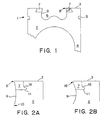
- Figure 1 is a longitudinal sectional view of the upper portion of a cast piston according to one embodiment of the present invention.
- the piston generally identified by reference numeral 1 includes a head 2 having a crown 3, and a piston skirt 4 extending from the head 2.
- the piston head 2 includes one or more grooves 5 which are of conventional design and provided to receive pistons rings (not shown).
- a combustion bowl 6 is formed in the piston head 2, which extends downwardly from the crown 3.
- Insert 7 is embedded in the piston head 2 at the crown 3 and surrounds combustion bowl 6. As shown, insert 7 defines an upper portion of the combustion bowl 6 with an undercut structure 8 at the crown surface of the piston 1 which is depicted in Fig. 1 as forming a sharp undercut edge.
- the undercut structure 8, of the combustion bowl 6 which is defined by insert 7 is not drawn exactly to scale in Fig. 1. However, the undercut structure 8 is depicted as being formed so as to have-an angle ("a" in Fig. 1)of less than 90° at the point where the inner surface 9 of the insert 7 intersects the piston crown 3.
- the side portions 10 of the combustion bowl 6 can be straight as depicted in Fig. 1, or curved so long as an undercut portion is provided at the upper edge of the combustion bowl 6.
- the inner surface 9 of the insert 7 intersects the upper surface of the piston crown 3 at an angle within the range of from about 45° to less than 90°, with an angle in the range of from about 60° to less than 90° being more preferred and an angle of from about 75° to less than about 85° being most preferred.
- the insert 7 includes a flange structure 11 which extends outwardly from a lower portion thereof. This flange 11 includes means for preventing rotation and lifting of the insert 7 during machining thereof. Flange 11 also can be used to properly align the insert 7 in a piston casting mold, as discussed herebelow.
- Figure 2a is an enlarged longitudinal sectional view of the undercut structure 8 of the insert 7 according to one embodiment of the present invention.
- the undercut structure 8 has a sharp or pointed edge structure which encircles the rim of the combustion bowl 6 and projects toward the center of opening 12.
- Figure 2a further depicts the side portions 10 of the inner surface 9 of combustion bowl 6 as having a curved shape.
- Figure 2b is an enlarged longitudinal sectional view of the undercut structure 8 of the insert 7 according to another embodiment of the present invention.
- the undercut structure 8 is not provided at the crown 3 of the piston 1 as in the case of the undercut structure 8 shown in Figs. 1 and 2b. Instead, the undercut structure 8 in Fig. 2b does not intersect the crown 3 of the piston. That is, the undercut structure 8 is spaced apart from the crown surface of the piston.
- the undercut structure 8 in the embodiments illustrated in Figs. 2a and 2b and similar modifications within the scope of the present invention function in a similar manner to contain combustible gaseous fuels in the combustion bowl prior to ignition thereof. Accordingly, it can be appreciated that the exact shape of the undercut structure 8 is not limited to that shown in these figures.
- FIG. 3 is a top view of a piston insert 7 according to one embodiment of the present invention.
- the insert 7 is generally a ring-shaped or annular structure, having a substantially circular opening 12 therethrough.
- the flange 11 extends radially outward from a main annular ring structure 13 and includes a number of scallops 14 which can be symmetrically spaced about the insert 7 as shown.
- the scallops 14 preferably are defined by curved cutouts formed in flange 11 as shown.
- rectangular cutouts, defining rectangular arm structures could also be used.
- other cutout shapes such as triangular, trapezoidal, or other curved shapes could be used to produce complementary shaped extensions on flange 11.
- the insert 7 is provided with several notches 15 which are located in the bottom surface thereof. These illustrated notches 15, or a different arrangement of similar notches, can be used to grasp the insert 7 from the top with a tool that can be inserted through opening 12 and manipulated to engage notches 15.
- the notches 15 thus can be used to position the insert 7 into a piston casting mold with a manually operated tool or with an automated handler.
- Providing the notches 15 in the lower surface of the insert 7 facilitates positioning of the insert 7 in a casting mold used in a head-up casting process.
- such notches could be provided in the upper surface of the insert 7 and used to position the insert 7 in a casting mold which casts a piston in a head-down casting process.
- Figure 4 is a side view of the piston insert of Fig. 3.
- flange 11 extends outwardly from a lower portion of main ring structure 11.
- a transition structure 16 can be provided between the flange 11 and the main ring structure 13.
- the transition structure 16 strengthens the connection between the flange 11 and main ring structure 13.
- the insert 7 is formed by a sintering process such as powder metallurgy, which produces an integral structure.
- Figure 5 is a bottom view of the piston insert of Fig. 3.
- Figure 5 depicts the notches 15 which are provided in the bottom surface of the insert 7 at the periphery of opening 12.
- Figure 5 also depicts the scallops 14 as having bevelled or preferably curved outer edges 17. This bevelled or preferred curved structure is provided on both the upper and lower surfaces of the scallops 14 as seen in Fig. 3.
- Figure 6 is a sectional view of the piston insert of Fig. 3, taken along line VI-VI.
- Figure 6 depicts the transitional structure 16 and curved shape of the outer edges of scallops 14.
- Figure 6 also shows the notches 15 on the lower surface of the insert 7.
- the embodiment of the insert 7 shown in Figs. 3-6 depicts the insert 7 in its unmachined state. That is, the insert 7 depicted in Figs. 3-6 is embedded into a cast piston during a casting process and subsequently machined during a machining process which forms combustion bowl 6. Accordingly, the notches 15 shown in Figs. 3-6 are eliminated during the machining process so that the insert has the final shape as depicted in Fig. 1.
- the flange 11 mechanically bonds the insert 7 in the piston head 2 as a result of the casting process.
- the curved features of the flange 11, including the smooth shape of the scallops 14, the edges 17 thereof, and the transition structure 16, ensure that molten metal, such as aluminum, fully encompasses and surrounds the insert 7 during a casting process so that there are substantially no gaps between the insert and the piston head.
- molten metal such as aluminum
- the use of an insert 7 made from a material which has thermal expansion characteristics similar to those of the material from which the piston is cast further prevents the formation of gaps or cracks at the interface between the piston head and the embedded insert.
- a stainless steel insert was included in a cast aluminum piston and found to resist cracking at the aluminum/stainless steel interface.
Landscapes
- Engineering & Computer Science (AREA)
- Chemical & Material Sciences (AREA)
- Mechanical Engineering (AREA)
- Combustion & Propulsion (AREA)
- General Engineering & Computer Science (AREA)
- Ceramic Engineering (AREA)
- Pistons, Piston Rings, And Cylinders (AREA)
Claims (15)
- Gegossener Kolben (1), der einen Kolbenkopf (2) umfaßt, umfassend eine Kranzfläche (3), einen Kolbenmantel (4), der sich vom Kolbenkopf (2) nach unten erstreckt, eine Brennraummulde (6), die im Kolbenkopf (3) gebildet ist, wobei die Brennraummulde eine Seitenwand aufweist und sich von der Kranzfläche nach unten erstreckt, und einen Metalleinsatz (7), der in Kolbenkopf (3) an der Kranzfläche vorgesehen ist, wobei der Metalleinsatz einen oberen Abschnitt der Brennraummulde (6) festlegt und in der Seitenwand eine Unterschnittstruktur (8) aufweist, wobei der Einsatz (7) mechanisch im gegossenen Kolben (1) befestigt ist und mit strukturellen Elementen versehen ist, die einen Flansch (11) umfassen, der eine Vielzahl von zahnförmigen Vorsprüngen umfaßt, wobei sich der Flansch (11) in den gegossenen Kolben hinein erstreckt und Dreh- und Hebekräften standhält.
- Gegossener Kolben nach Anspruch 1, in dem die Unterschnittstruktur eine Unterschnittkante (8) umfaßt, die die Kranzfläche schneidet.
- Gegossener Kolben nach Anspruch 2, in dem die Unterschnittstruktur einen Winkel aufweist, der am Schnitt der Kranzfläche und einer Innenfläche der Brennraummulde (6) festgelegt ist, der weniger als 90° beträgt.
- Gegossener Kolben nach Anspruch 3, in dem der Winkel von ungefähr 60° bis weniger als 90° beträgt.
- Gegossener Kolben nach Anspruch 2, in dem der Winkel von ungefähr 75° bis weniger als ungefähr 85° beträgt.
- Gegossener Kolben nach Anspruch 2 bis 5, in dem die Unterschnittstruktur eine scharfe Kante umfaßt.
- Gegossener Kolben nach irgendeinem vorstehenden Anspruch, in dem die Brennraummulde (6) gekrümmte obere Seitenwände (9) aufweist.
- Gegossener Kolben nach irgendeinem vorstehenden Anspruch, in dem der Metalleinsatz (7) eine Ringstruktur aufweist, wobei sich der Flansch (11) vom einem unteren Abschnitt der Ringstruktur nach außen erstreckt.
- Gegossener Kolben nach irgendeinem vorstehenden Anspruch, in dem der gegossene Kolben und der Metalleinsatz aus Metallen hergestellt sind, die im wesentlichen ähnliche Wärmeausdehnungseigenschaften aufweisen.
- Gegossener Kolben nach Anspruch 9, in dem der Kolben aus Aluminium und die Einlage aus rostfreiem Stahl hergestellt sind.
- Metalleinsatz (7) zur Verwendung bei der Herstellung eines gegossenen Kolbens (1) nach Anspruch 1, wobei der Einsatz (7) folgendes umfaßt:
eine Ringstruktur (13) und einen Flansch (11), der an einem unteren Abschnitt der Ringstruktur (13) vorgesehen ist und sich davon nach außen erstreckt, dadurch gekennzeichnet, daß der Flansch (11) eine Vielzahl von zahnförmigen Vorsprüngen umfaßt. - Metalleinsatz nach Anspruch 11, umfassend eine mittlere Durchbohrung und weiter umfassend Mittel zum Greifen des Einsatzes, wobei das Mittel zum Greifen mindestens eine Kerbe aufweist, die angrenzend an die Durchbohrung gebildet ist.
- Metalleinsatz nach Anspruch 11 oder Anspruch 12, in dem die zahnförmigen Vorsprünge gekrümmte Kanten aufweisen.
- Verwendung eines Metalleinsatzes (7) nach irgendeinem der Ansprüche 11 bis 13 in einem Verfahren zur Herstellung eines gegossenen Kolbens (1) nach irgendeinem der Ansprüche 1 bis 10, wobei das Verfahren die folgenden Schritte umfaßt:Bereitstellen einer Kolbengußform;Anordnen des Metalleinsatzes (7) in der Kolbengußform;Gießen des Kolbens (1) in der Kolbengußform, so daß der Metalleinsatz (7) an der Kranzfläche des gegossenen Kolbens (1) angeordnet ist; undBearbeiten einer Brennraummulde (6) in einem Kopf (3) des gegossenen Kolbens (1), so daß der Metalleinsatz (7) einen oberen Abschnitt der Brennraummulde (6) festlegt und eine Unterschnittstruktur (8) in einer Seitenwand der Brennraummulde (6) bereitstellt.
- Verwendung nach Anspruch 14, in der der Guß des Kolbens (1) ein Schwerkraftguß ist.
Applications Claiming Priority (2)
| Application Number | Priority Date | Filing Date | Title |
|---|---|---|---|
| US08/649,079 US5660156A (en) | 1996-05-16 | 1996-05-16 | Cast piston having reinforced combustion bowl edge |
| US649079 | 1996-05-16 |
Publications (2)
| Publication Number | Publication Date |
|---|---|
| EP0807750A1 EP0807750A1 (de) | 1997-11-19 |
| EP0807750B1 true EP0807750B1 (de) | 2001-08-16 |
Family
ID=24603374
Family Applications (1)
| Application Number | Title | Priority Date | Filing Date |
|---|---|---|---|
| EP97303241A Expired - Lifetime EP0807750B1 (de) | 1996-05-16 | 1997-05-13 | Gegassener Kolben mit verstärktem Brennraummulderand |
Country Status (3)
| Country | Link |
|---|---|
| US (1) | US5660156A (de) |
| EP (1) | EP0807750B1 (de) |
| DE (1) | DE69706095T2 (de) |
Families Citing this family (20)
| Publication number | Priority date | Publication date | Assignee | Title |
|---|---|---|---|---|
| US5979298A (en) * | 1997-05-08 | 1999-11-09 | Zellner Pistons, Llc | Cooling gallery for pistons |
| DE19815485C2 (de) * | 1998-04-07 | 2000-01-05 | Federal Mogul Burscheid Gmbh | Kolben für Brennkraftmaschinen |
| US6170454B1 (en) | 1998-07-31 | 2001-01-09 | Techniphase Industries, Inc. | Piston apparatus and methods |
| US6189413B1 (en) | 1999-07-12 | 2001-02-20 | American Axle & Manufacturing, Inc. | Captive molding with dissimilar material insert |
| JP3847028B2 (ja) * | 1999-07-30 | 2006-11-15 | 株式会社日立製作所 | 内燃機関用ピストン及びその製造方法 |
| DE19952868B4 (de) * | 1999-11-03 | 2005-03-17 | Ks Kolbenschmidt Gmbh | Kolben und Kolbenanordnung |
| US8276563B2 (en) * | 2002-06-28 | 2012-10-02 | Cummins, Inc. | Internal combustion engine piston |
| US6705273B1 (en) * | 2002-09-30 | 2004-03-16 | International Engine Intellectual Property Company, Llc | Combustion chamber |
| US6868817B2 (en) * | 2002-12-13 | 2005-03-22 | International Engine Intellectual Property Company, Llc | Simplified combustion chamber |
| US6955165B2 (en) * | 2003-03-13 | 2005-10-18 | International Engine Intellectual Property Company, Llc | Three-reentrancy combustion chamber |
| US6725828B1 (en) * | 2003-06-17 | 2004-04-27 | Ford Global Technologies, Llc | Vortex-induced stratification combustion for direct injection spark ignition engines |
| DE10334476B4 (de) * | 2003-07-29 | 2008-05-08 | Ks Kolbenschmidt Gmbh | Feuerblech für einen Kolben mit einer Brennraummulde |
| JP2009503374A (ja) * | 2005-07-21 | 2009-01-29 | ジーケーエヌ シンター メタルズ, インコーポレーテッド | 鋳込インサート付連接棒 |
| DE102008031863A1 (de) * | 2008-07-05 | 2010-01-07 | Mahle International Gmbh | Einlegeteil für einen Kolben eines Verbrennungsmotors sowie mit dem Einlegeteil versehener Kolben oder Kolbenkopf |
| US9027529B2 (en) * | 2010-02-18 | 2015-05-12 | Volvo Technology Corporation | Piston positioned for reciprocal movement in a combustion engine cylinder |
| DE102011107774A1 (de) * | 2011-07-15 | 2013-01-17 | Mahle International Gmbh | Kolben für einen Verbrennungsmotor |
| US20160169152A1 (en) * | 2014-12-11 | 2016-06-16 | Caterpillar Inc. | Engine Piston |
| US10634089B2 (en) * | 2017-12-12 | 2020-04-28 | GM Global Technology Operations LLC | Diesel piston with sharp-step profile |
| US10400663B2 (en) * | 2017-12-18 | 2019-09-03 | Caterpillar Inc. | Piston bowl for improved combustion stability |
| DE102021211572A1 (de) | 2021-10-13 | 2023-04-13 | Fraunhofer-Gesellschaft zur Förderung der angewandten Forschung eingetragener Verein | Verbundgussverfahren unter Verformung eines Einlegeteils zur Vermeidung von Ein- oder Abrissen zwischen Gussmetall und Einlegeteil sowie Verbundbauteil |
Citations (1)
| Publication number | Priority date | Publication date | Assignee | Title |
|---|---|---|---|---|
| DE1032600B (de) * | 1956-02-23 | 1958-06-19 | Krauss Maffei Ag | Brennraum in einer der relativ zueinander bewegten Begrenzungswaende des Verbrennungsraumes der Zylinder von Zweitakt-Dieselbrennkraftmaschinen |
Family Cites Families (27)
| Publication number | Priority date | Publication date | Assignee | Title |
|---|---|---|---|---|
| DE238420C (de) * | 1900-01-01 | |||
| US1296591A (en) * | 1916-03-07 | 1919-03-04 | Aluminum Castings Company | Piston-casting. |
| US1759509A (en) * | 1926-09-23 | 1930-05-20 | Aluminum Co Of America | Method of making pistons |
| US2473254A (en) * | 1945-02-08 | 1949-06-14 | Lister & Co Ltd R A | Piston with annular heat dam in the head |
| US2685729A (en) * | 1951-05-10 | 1954-08-10 | Frank A Bower | Method of making composite piston structures |
| US2959161A (en) * | 1957-08-20 | 1960-11-08 | Ustav Pro Vyzkum Motorovych Vo | Internal-combustion compression-ignition engine with localised self-ignition of the fuel |
| FR1288819A (fr) * | 1961-02-14 | 1962-03-30 | Piston perfectionné | |
| FR1355919A (fr) * | 1963-04-02 | 1964-03-20 | Zollner Corp | Piston pour un moteur comprenant une tête en aluminium munie d'une barrière thermique |
| US3251349A (en) * | 1964-01-09 | 1966-05-17 | Continental Aviat & Eng Corp | Piston construction |
| US3369465A (en) * | 1965-02-08 | 1968-02-20 | John L. Harrah | Pistons for internal combustion engines |
| DE2136594A1 (de) * | 1970-07-30 | 1972-02-03 | Mondial Piston Dott GaIh Ercole & C s p a , Turm (Italien) | Kolben mit einem die Mundung des Verbrennungsraumes umgebenden Einsatz stuck aus Metallegierung auf Kupferbasis |
| DE2624412C3 (de) * | 1976-05-31 | 1983-12-01 | Alcan Aluminiumwerk Nürnberg GmbH, 6000 Frankfurt | Verfahren zur Herstellung von Kolben mit einem Ringkanal |
| US4137887A (en) * | 1976-06-11 | 1979-02-06 | Perkins Engines Limited | Pistons for internal combustion engines |
| GB2090779B (en) * | 1981-01-13 | 1984-12-19 | Imp Clevite Inc | Wear resistant insert for cast lightweight pistons and method of casting |
| IT1194060B (it) * | 1981-07-31 | 1988-09-14 | Ae Borgo Spa | Pistone per motori diesel con camera di combustione isolata |
| US4488522A (en) * | 1981-08-28 | 1984-12-18 | Ae Plc | Pistons including inserts |
| DE3144123A1 (de) * | 1981-11-06 | 1983-05-19 | Karl Schmidt Gmbh, 7107 Neckarsulm | Leichtmetallkolben |
| DE3321212A1 (de) * | 1983-06-11 | 1984-12-13 | Kolbenschmidt AG, 7107 Neckarsulm | Aus einem leichtmetallwerkstoff gegossenes bauteil fuer brennkraftmaschinen |
| DE3430056C1 (de) * | 1984-08-16 | 1986-01-16 | Mahle Gmbh, 7000 Stuttgart | Tauchkolben mit faserverstaerkter Brennraummulde fuer Verbrennungsmotoren |
| JPH0750049Y2 (ja) * | 1986-11-25 | 1995-11-15 | イズミ工業株式会社 | 熱膨張抑制ピストン用ストラット |
| JP2691770B2 (ja) * | 1989-04-20 | 1997-12-17 | イズミ工業株式会社 | 内燃機関用アルミニウム合金ピストン |
| DE3932562A1 (de) * | 1989-09-29 | 1991-04-11 | Kolbenschmidt Ag | Vorrichtung zur herstellung von leichtmetallkolben fuer verbrennungskraftmaschinen |
| BR9204730A (pt) * | 1992-12-23 | 1994-06-28 | Metal Leve Sa | Embolo com inserto de reforço |
| DE4328619C2 (de) * | 1993-08-26 | 1995-08-10 | Peak Werkstoff Gmbh | Partiell verstärktes Al-Gußbauteil und Verfahren zu dessen Herstellung |
| US5425306A (en) * | 1993-11-23 | 1995-06-20 | Dana Corporation | Composite insert for use in a piston |
| DE4340267B4 (de) * | 1993-11-26 | 2007-08-02 | Mahle Gmbh | Leichtmetall-Kolben mit einer Verbrennungsmulde |
| US5476076A (en) * | 1994-12-06 | 1995-12-19 | Zhou; Zhishan | Internal combustion piston engine utilizing interference movable fit technology |
-
1996
- 1996-05-16 US US08/649,079 patent/US5660156A/en not_active Expired - Lifetime
-
1997
- 1997-05-13 EP EP97303241A patent/EP0807750B1/de not_active Expired - Lifetime
- 1997-05-13 DE DE69706095T patent/DE69706095T2/de not_active Expired - Fee Related
Patent Citations (1)
| Publication number | Priority date | Publication date | Assignee | Title |
|---|---|---|---|---|
| DE1032600B (de) * | 1956-02-23 | 1958-06-19 | Krauss Maffei Ag | Brennraum in einer der relativ zueinander bewegten Begrenzungswaende des Verbrennungsraumes der Zylinder von Zweitakt-Dieselbrennkraftmaschinen |
Also Published As
| Publication number | Publication date |
|---|---|
| DE69706095D1 (de) | 2001-09-20 |
| DE69706095T2 (de) | 2002-01-03 |
| US5660156A (en) | 1997-08-26 |
| EP0807750A1 (de) | 1997-11-19 |
Similar Documents
| Publication | Publication Date | Title |
|---|---|---|
| EP0807750B1 (de) | Gegassener Kolben mit verstärktem Brennraummulderand | |
| EP0118204B1 (de) | Verstärkung von Kolben aus Aluminium oder Aluminiumlegierung | |
| EP0162602B1 (de) | Verstärkter Kolben | |
| EP0796687B9 (de) | Verfahren zur Herstellung eines Kolbens einer Brennkraftmaschine und nach diesem Verfahren hergestellter Kolben | |
| CA1240132A (en) | Manufacture of pistons | |
| US5979298A (en) | Cooling gallery for pistons | |
| US3152523A (en) | Piston for internal combustion engines | |
| US4939984A (en) | Investment-cast piston crown cap with encapsulated non-metallic insulating core | |
| JP3145094B2 (ja) | 軽量金属製ピストン | |
| US4649806A (en) | Composite ceramic/metal piston assembly and method of making | |
| JPS6313405Y2 (de) | ||
| EP0144145B2 (de) | Kolben | |
| JPH0370814A (ja) | 副室の断熱構造及びその製造法 | |
| EP0870919B1 (de) | Brennkraftmaschinenkolben und Verfahren zu seiner Herstellung | |
| GB2158185A (en) | Reinforced light metal pistons | |
| JPH07132362A (ja) | シリンダブロックおよびその製造方法 | |
| US20040194307A1 (en) | Manufacturing pistons | |
| JPH04272455A (ja) | 燃焼室の製造法 | |
| EP0240308B1 (de) | Brennkraftmaschinenkolben und Verfahren zu dessen Verstärkung | |
| JP2623799B2 (ja) | 内燃機関のピストン | |
| GB2182875A (en) | The reinforcement of pistons of aluminium or aluminium alloy | |
| CA1335179C (en) | Piston assembly and piston member thereof having a predetermined compression height to diameter ratio | |
| GB2209014A (en) | Piston | |
| JPS6350613A (ja) | バルブスプリングリテ−ナ | |
| JPH04276161A (ja) | 燃焼室の構造及びその製造法 |
Legal Events
| Date | Code | Title | Description |
|---|---|---|---|
| PUAI | Public reference made under article 153(3) epc to a published international application that has entered the european phase |
Free format text: ORIGINAL CODE: 0009012 |
|
| AK | Designated contracting states |
Kind code of ref document: A1 Designated state(s): DE FR GB |
|
| 17P | Request for examination filed |
Effective date: 19980311 |
|
| 17Q | First examination report despatched |
Effective date: 19990315 |
|
| RAP1 | Party data changed (applicant data changed or rights of an application transferred) |
Owner name: ZOLLNER PISTONS, LLC |
|
| RAP1 | Party data changed (applicant data changed or rights of an application transferred) |
Owner name: KOLBENSCHMIDT ACQUISITIONS, INC. |
|
| GRAG | Despatch of communication of intention to grant |
Free format text: ORIGINAL CODE: EPIDOS AGRA |
|
| GRAG | Despatch of communication of intention to grant |
Free format text: ORIGINAL CODE: EPIDOS AGRA |
|
| GRAH | Despatch of communication of intention to grant a patent |
Free format text: ORIGINAL CODE: EPIDOS IGRA |
|
| RAP1 | Party data changed (applicant data changed or rights of an application transferred) |
Owner name: KARL SCHMIDT UNISIA, ZOLLNER DIVISION, INC. |
|
| GRAH | Despatch of communication of intention to grant a patent |
Free format text: ORIGINAL CODE: EPIDOS IGRA |
|
| GRAA | (expected) grant |
Free format text: ORIGINAL CODE: 0009210 |
|
| AK | Designated contracting states |
Kind code of ref document: B1 Designated state(s): DE FR GB |
|
| REF | Corresponds to: |
Ref document number: 69706095 Country of ref document: DE Date of ref document: 20010920 |
|
| ET | Fr: translation filed | ||
| REG | Reference to a national code |
Ref country code: GB Ref legal event code: IF02 |
|
| PLBE | No opposition filed within time limit |
Free format text: ORIGINAL CODE: 0009261 |
|
| STAA | Information on the status of an ep patent application or granted ep patent |
Free format text: STATUS: NO OPPOSITION FILED WITHIN TIME LIMIT |
|
| 26N | No opposition filed | ||
| PGFP | Annual fee paid to national office [announced via postgrant information from national office to epo] |
Ref country code: GB Payment date: 20030514 Year of fee payment: 7 |
|
| PGFP | Annual fee paid to national office [announced via postgrant information from national office to epo] |
Ref country code: FR Payment date: 20030520 Year of fee payment: 7 |
|
| PGFP | Annual fee paid to national office [announced via postgrant information from national office to epo] |
Ref country code: DE Payment date: 20030626 Year of fee payment: 7 |
|
| PG25 | Lapsed in a contracting state [announced via postgrant information from national office to epo] |
Ref country code: GB Free format text: LAPSE BECAUSE OF NON-PAYMENT OF DUE FEES Effective date: 20040513 |
|
| PG25 | Lapsed in a contracting state [announced via postgrant information from national office to epo] |
Ref country code: DE Free format text: LAPSE BECAUSE OF NON-PAYMENT OF DUE FEES Effective date: 20041201 |
|
| GBPC | Gb: european patent ceased through non-payment of renewal fee |
Effective date: 20040513 |
|
| PG25 | Lapsed in a contracting state [announced via postgrant information from national office to epo] |
Ref country code: FR Free format text: LAPSE BECAUSE OF NON-PAYMENT OF DUE FEES Effective date: 20050131 |
|
| REG | Reference to a national code |
Ref country code: FR Ref legal event code: ST |