EP0807736B1 - Serrure encastrée - Google Patents
Serrure encastrée Download PDFInfo
- Publication number
- EP0807736B1 EP0807736B1 EP97103818A EP97103818A EP0807736B1 EP 0807736 B1 EP0807736 B1 EP 0807736B1 EP 97103818 A EP97103818 A EP 97103818A EP 97103818 A EP97103818 A EP 97103818A EP 0807736 B1 EP0807736 B1 EP 0807736B1
- Authority
- EP
- European Patent Office
- Prior art keywords
- lock
- changer
- latch
- lock according
- lever
- Prior art date
- Legal status (The legal status is an assumption and is not a legal conclusion. Google has not performed a legal analysis and makes no representation as to the accuracy of the status listed.)
- Expired - Lifetime
Links
Images

Classifications
-
- E—FIXED CONSTRUCTIONS
- E05—LOCKS; KEYS; WINDOW OR DOOR FITTINGS; SAFES
- E05C—BOLTS OR FASTENING DEVICES FOR WINGS, SPECIALLY FOR DOORS OR WINDOWS
- E05C17/00—Devices for holding wings open; Devices for limiting opening of wings or for holding wings open by a movable member extending between frame and wing; Braking devices, stops or buffers, combined therewith
- E05C17/02—Devices for holding wings open; Devices for limiting opening of wings or for holding wings open by a movable member extending between frame and wing; Braking devices, stops or buffers, combined therewith by mechanical means
- E05C17/04—Devices for holding wings open; Devices for limiting opening of wings or for holding wings open by a movable member extending between frame and wing; Braking devices, stops or buffers, combined therewith by mechanical means with a movable bar or equivalent member extending between frame and wing
- E05C17/12—Devices for holding wings open; Devices for limiting opening of wings or for holding wings open by a movable member extending between frame and wing; Braking devices, stops or buffers, combined therewith by mechanical means with a movable bar or equivalent member extending between frame and wing consisting of a single rod
- E05C17/16—Devices for holding wings open; Devices for limiting opening of wings or for holding wings open by a movable member extending between frame and wing; Braking devices, stops or buffers, combined therewith by mechanical means with a movable bar or equivalent member extending between frame and wing consisting of a single rod pivoted only at one end and having an elongated slot
- E05C17/166—Security devices
-
- E—FIXED CONSTRUCTIONS
- E05—LOCKS; KEYS; WINDOW OR DOOR FITTINGS; SAFES
- E05B—LOCKS; ACCESSORIES THEREFOR; HANDCUFFS
- E05B59/00—Locks with latches separate from the lock-bolts or with a plurality of latches or lock-bolts
-
- E—FIXED CONSTRUCTIONS
- E05—LOCKS; KEYS; WINDOW OR DOOR FITTINGS; SAFES
- E05C—BOLTS OR FASTENING DEVICES FOR WINGS, SPECIALLY FOR DOORS OR WINDOWS
- E05C9/00—Arrangements of simultaneously actuated bolts or other securing devices at well-separated positions on the same wing
- E05C9/02—Arrangements of simultaneously actuated bolts or other securing devices at well-separated positions on the same wing with one sliding bar for fastening when moved in one direction and unfastening when moved in opposite direction; with two sliding bars moved in the same direction when fastening or unfastening
- E05C9/026—Arrangements of simultaneously actuated bolts or other securing devices at well-separated positions on the same wing with one sliding bar for fastening when moved in one direction and unfastening when moved in opposite direction; with two sliding bars moved in the same direction when fastening or unfastening comprising key-operated locks, e.g. a lock cylinder to drive auxiliary deadbolts or latch bolts
-
- Y—GENERAL TAGGING OF NEW TECHNOLOGICAL DEVELOPMENTS; GENERAL TAGGING OF CROSS-SECTIONAL TECHNOLOGIES SPANNING OVER SEVERAL SECTIONS OF THE IPC; TECHNICAL SUBJECTS COVERED BY FORMER USPC CROSS-REFERENCE ART COLLECTIONS [XRACs] AND DIGESTS
- Y10—TECHNICAL SUBJECTS COVERED BY FORMER USPC
- Y10T—TECHNICAL SUBJECTS COVERED BY FORMER US CLASSIFICATION
- Y10T292/00—Closure fasteners
- Y10T292/08—Bolts
- Y10T292/0801—Multiple
- Y10T292/0834—Sliding
- Y10T292/0836—Operating means
- Y10T292/0844—Lever
-
- Y—GENERAL TAGGING OF NEW TECHNOLOGICAL DEVELOPMENTS; GENERAL TAGGING OF CROSS-SECTIONAL TECHNOLOGIES SPANNING OVER SEVERAL SECTIONS OF THE IPC; TECHNICAL SUBJECTS COVERED BY FORMER USPC CROSS-REFERENCE ART COLLECTIONS [XRACs] AND DIGESTS
- Y10—TECHNICAL SUBJECTS COVERED BY FORMER USPC
- Y10T—TECHNICAL SUBJECTS COVERED BY FORMER US CLASSIFICATION
- Y10T70/00—Locks
- Y10T70/50—Special application
- Y10T70/5093—For closures
- Y10T70/5155—Door
- Y10T70/5199—Swinging door
- Y10T70/5226—Combined dead bolt and latching bolt
Definitions
- the invention relates to a lock, in particular a Mortise lock for an outer door, according to the preamble of Claim 1.
- Such locks can be found on front doors or Apartment entrance doors use, being at the most common training as a mortise lock in a Lock pocket of the door leaf inserted and over one faceplate or similar in the door leaf being held. After attaching this mortise lock at the door there are still door handles and one Lock cylinder mounted.
- a lever handle is usually only on the inside, while on the outside a so-called Knob, i.e. a handle that cannot be actuated is installed.
- the latch can be withdrawn with the help of the rotating door handle become.
- Furthermore can be locked with the help of the key both from the outside as well as lock from the inside as well back close.
- An additional bolt box is known from DE 35 03 466 A1 which has a connecting rod from the main lock is drivable.
- This main lock can e.g. according to EP 575 701 A1 or DE 38 36 694 A1.
- EP 0 575 701 A1 describes an espagnolette lock, that corresponds to the preamble of claim 1.
- the invention is therefore based on the object Locking device of the type mentioned above to further develop that even when opening the door Actuation of the main lock case still a certain security is guaranteed against complete opening.
- This task is carried out in a castle of the type mentioned solved according to the invention in that in addition to the change Change lever is provided that the change lever on a second control plate is articulated and that the control plate with a second drive rod e.g. for a locking swivel lock connected is.
- the lock according to the invention can in addition to Additional lock boxes e.g. another locking swivel lock be provided, which is actuated via a second drive rod becomes.
- This second drive rod is from a second Controlled control plate, which is provided in the main lock.
- This second control plate is in turn owned by one Change lever operated, which is connected to the change.
- the additional lock boxes and that Locking swivel lock independently of one another by means of two Push rods actuated. That way they can Additional lock boxes are controlled so that they together open with the main lock, whereas that Locking swivel lock still its locking position maintains, i.e. the locking bolt in its pre-closed position remains. Only by separately controlling the second one Driving rod or the locking bolt is over the knob this bolt closed back so that the door completely can be opened.
- the door may be opened a crack, a complete one Swinging open is prevented. This way too an accidental complete opening or unlocking of the door prevented.
- the change lever connected with the change, in particular via a pin-slot connection with which is coupled.
- This pin-slot connection allows relative movements between the Change lever and the lever so that the actuation of one does not have to immediately cause the other to operate.
- the Change lever with an elongated hole in which a Pin of the change engages. It is in the rest position of the Connect the pin to one end of the slot. Becomes So the change lever moves in one direction, then the change taken over the adjacent pin. Becomes however the change moves in the same direction, then runs the pin freely in the slot without the change lever is operated.
- the Change lever has a control edge on which a Control cam of an actuable by means of the lock cylinder Gearbox, especially a planetary gear attack.
- a Control cam of an actuable by means of the lock cylinder Gearbox especially a planetary gear attack.
- the change lever is shifted in the lock and thereby moves the second drive rod.
- the change lever operated the change, so that the Trap is drawn. So the door can go through from the outside Actuation of a key to be opened, all Locks are moved into their open position.
- the mortise and tenon connection of the change lever and the Change is selected so that when the change lever is actuated the change is driven, whereas when pressing the Alternating uncoupled by means of the follower of the change lever is. A closing of the bolt of the Locking swivel lock is therefore by means of the handle locked out.
- the change lever is a Led in a first control plate and is from the Effective range of a planetary gear can be deflected out. To this He only becomes wise when the trap is pulled in, but not when Close the latch of the change lever from Planetary gear operated.
- the second control plate in Slidable in the direction of the second drive rod in the lock is stored.
- the second control plate extends in parallel to the first control plate and only has the function of Drive the second drive rod.
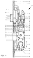
- Figure 1 is a plan view with a total of 1 designated main or lock housing shown, which on the side facing the viewer by means of a removed and therefore not shown in the drawing Cover is closed.
- a trap 2 Inside the case are a trap 2 and a latch 3 in the sense of the double arrow 4 can be moved.
- a follower 5 in the sense of Double arrow 6 rotatably mounted. She has a breakthrough 7, in particular a square opening, for receiving a Square mandrel of a pusher or other actuating element for the trap 2.
- a radially projecting approach 8 the Handle nut 5 is at the upper end of a slidable Intermediate piece 10, the lower end of the upper end a return spring (not shown) is assigned.
- a lock cylinder 22nd known type, for example a profile cylinder used.
- This lock cylinder 22 is by means of a the lock cylinder 22 inserted key 36 in the sense of the double arrow 24 is rotated about the geometric axis 45 and causes an intermediate gear, in particular a planetary gear 44 the rotation of a gear 23 and thereby pushing out or pulling back the latch 3.
- the Lock bit of the lock cylinder 22, not shown drives in this embodiment in a known manner slotted ring gear. Its rotational movement is over two Transfer idler gears to gear 23. This drives in known manner to a first control plate 25, via which first drive rods 42 and 43 up and down are driven.
- the gear 23 bears on its side facing the viewer Front a control cam 26 which when turning the Gear 23 a control edge 27 of a change lever 28 drives.
- This change lever 28 is a pin 29 in a link 30 provided in the first control plate 25 is guided and by means of a pin 31 on a second Control plate 32 articulated.
- This second control plate 32 is displaceable in the direction of the double arrow 9 Lock housing 1 stored.
- An elongated hole 33 is also provided on the change lever 28, in which engages a pin 34 of a link 35 which with the Control nut 17 is pivotally connected.
- the displacement of the change lever 28 described above the control cam 26 of the gear 23 also causes one Displacement of the handlebar 35, the pin 34 at the end of Elongated hole 33 is present.
- the displacement of the handlebar 35, the is articulated to the control nut 17, causes a rotation of the control nut 17 in the direction of the arrow 13, whereby, as also described above, the trap 2 over the end 18, which bears against the trap tail 20, is withdrawn. The door can then be opened.
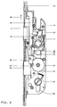
- the follower 5 is activated by pressing Pusher not shown in the direction of arrow 40 around geometric axis 41 rotated. This causes a twist the control nut 17 in the same direction, i.e. in Clockwise direction, which over the end 18 which on the trap tail 20, the trap 2 in the direction of Arrow 14 is withdrawn.
- the handlebar 35 moved because it is articulated with the control nut washer 17th connected is.
- the pin 34 moves in the slot 33.
- the change lever 28 is taken along by the handlebar 35 not because the pin 34 from the change lever 28 via the slot 33 is uncoupled. The change lever 28 thus remains in its rest position shown in Figure 1 and Figure 3.
- a locking swivel lock which is in communication with the second drive rod 39 not operated so that the door is not fully opened can be, but only as far as this Locking swivel lock allows.
Landscapes
- Engineering & Computer Science (AREA)
- Mechanical Engineering (AREA)
- Lock And Its Accessories (AREA)
- Clamps And Clips (AREA)
- Memory System Of A Hierarchy Structure (AREA)
- Scissors And Nippers (AREA)
Claims (10)
- Serrure (1), en particulier serrure à mortaiser pour porte extérieure, avec un pêne dormant (3) et un pêne demi-tour (2) agencés parallèlement mobiles en translation dans un boítier de serrure (1), dans laquelle le pêne dormant (3) est actionnable au moyen d'une clé (36) et le pêne demi-tour (2) est actionnable soit au moyen d'une poignée à fouillot (5) soit par l'intermédiaire d'un balancier (17, 35) au moyen de la clé (36), avec un perçage (21) destiné à recevoir un cylindre (22), le balancier (17, 35) pouvant être entraíné par le panneton du cylindre (22), et avec deux tringles parallèles d'actionnement de dispositifs de verrouillage supplémentaires, caractérisée en ce qu'en plus du balancier (17, 35) est prévu un levier de balancier (28), en ce que le levier de balancier (28) est articulé à une deuxième plaque de commande (32) et en ce que la deuxième plaque de commande (32) est reliée à la deuxième tringle (39) d'une serrure d'entrebailleur par exemple.
- Serrure selon la revendication 1, caractérisée en ce que le levier de balancier (28) est relié au balancier (17, 35) et est couplé à ce dernier notamment par une liaison à tenon et trou (33, 34).
- Serrure selon la revendication 2, caractérisée en ce que le levier de balancier (28) présente un trou oblong (33) dans lequel s'engage un tenon (34) du balancier (17, 35), en particulier d'une tige de liaison (35).
- Serrure selon la revendication 3, caractérisée en ce que lorsque la serrure est en position de repos, le tenon (34) est en appui contre une extrémité du trou oblong (33).
- Serrure selon l'une des revendications précédentes, caractérisée en ce que le levier de balancier (28) présente une arête de commande (27) avec laquelle coopère en appui une came de commande (26) d'un mécanisme actionnable au moyen du cylindre de fermeture (22), en particulier d'un engrenage épicycloïdal (44).
- Serrure selon l'une des revendications précédentes, caractérisée en ce que l'actionnement du levier de balancier (28) a pour effet d'entraíner le balancier (17, 35).
- Serrure selon l'une des revendications précédentes, caractérisée en ce que l'actionnement du balancier (17, 35) au moyen du fouillot de poignée (5) a pour effet de désaccoupler le levier de balancier (28).
- Serrure selon l'une des revendications précédentes, caractérisée en ce que le levier de balancier (28) est guidé par une coulisse (30) dans une première plaque de commande (25) et peut être guidé hors de la zone d'action d'un engrenage épicycloïdal (44).
- Serrure selon l'une des revendications précédentes, caractérisée en ce que la deuxième plaque de commande (32) est montée mobile en translation en direction de la deuxième tringle (39) à l'intérieur du boítier de serrure.
- Serrure selon l'une des revendications précédentes, caractérisée en ce que le balancier se compose d'une tige de liaison (35) et d'un disque de Pouillot de commande (17) articulé à celle-ci, le disque de fouillot de commande (17) en particulier étant monté rotatif sur le fouillot de poignée (5) et étant solidaire en mouvement du pêne demi-tour (2).
Applications Claiming Priority (2)
| Application Number | Priority Date | Filing Date | Title |
|---|---|---|---|
| DE29608862U | 1996-05-17 | ||
| DE29608862U DE29608862U1 (de) | 1996-05-17 | 1996-05-17 | Schloß, insbesondere Einsteckschloß |
Publications (3)
| Publication Number | Publication Date |
|---|---|
| EP0807736A2 EP0807736A2 (fr) | 1997-11-19 |
| EP0807736A3 EP0807736A3 (fr) | 1998-03-11 |
| EP0807736B1 true EP0807736B1 (fr) | 2002-11-20 |
Family
ID=8024058
Family Applications (1)
| Application Number | Title | Priority Date | Filing Date |
|---|---|---|---|
| EP97103818A Expired - Lifetime EP0807736B1 (fr) | 1996-05-17 | 1997-04-03 | Serrure encastrée |
Country Status (4)
| Country | Link |
|---|---|
| US (1) | US5878605A (fr) |
| EP (1) | EP0807736B1 (fr) |
| AT (1) | ATE228196T1 (fr) |
| DE (2) | DE29608862U1 (fr) |
Families Citing this family (17)
| Publication number | Priority date | Publication date | Assignee | Title |
|---|---|---|---|---|
| DE29605517U1 (de) * | 1996-03-26 | 1997-07-24 | Gretsch-Unitas GmbH Baubeschläge, 71254 Ditzingen | Verriegelungseinrichtung |
| DE29719611U1 (de) * | 1997-11-05 | 1999-03-11 | Gretsch-Unitas GmbH Baubeschläge, 71254 Ditzingen | Schloß, insbesondere Einsteckschloß für eine Außentür |
| AT406496B (de) * | 1998-07-23 | 2000-05-25 | Roto Frank Eisenwaren | Mehrriegelschloss |
| DE19855402C1 (de) * | 1998-12-01 | 2000-05-25 | Dorma Gmbh & Co Kg | Zweiflügelige Tür, insbesondere Feuerschutztür |
| US6282929B1 (en) * | 2000-02-10 | 2001-09-04 | Sargent Manufacturing Company | Multipoint mortise lock |
| AUPR604601A0 (en) * | 2001-06-29 | 2001-07-26 | Gainsborough Hardware Industries Limited | A mortice lock |
| US6871451B2 (en) | 2002-03-27 | 2005-03-29 | Newell Operating Company | Multipoint lock assembly |
| AT413125B (de) * | 2003-07-10 | 2005-11-15 | Roto Frank Eisenwaren | Schlüsselbetätigbares mehrriegelschloss |
| US7404306B2 (en) * | 2004-01-29 | 2008-07-29 | Newell Operating Company | Multi-point door lock and offset extension bolt assembly |
| US7946080B2 (en) | 2007-01-29 | 2011-05-24 | Newell Operating Company | Lock assembly |
| US8398126B2 (en) * | 2007-05-21 | 2013-03-19 | Truth Hardware Corporation | Multipoint lock mechanism |
| US7661279B2 (en) * | 2008-01-23 | 2010-02-16 | Door & Window Hardware Co. | Lock assembly |
| US8899635B2 (en) * | 2008-10-03 | 2014-12-02 | Truth Hardware Corporation | Sliding door multipoint mortise lock with shoot bolts |
| US8550506B2 (en) * | 2009-06-30 | 2013-10-08 | Truth Hardware Corporation | Multi-point mortise lock mechanism for swinging door |
| US8875549B2 (en) | 2012-10-24 | 2014-11-04 | Door & Window Hardware Co. | Lock assembly |
| CN105317290B (zh) | 2014-06-20 | 2019-04-19 | 真理五金制品公司 | 锁组件、滑动门组件以及锁致动器组件 |
| AT14920U1 (de) * | 2015-02-19 | 2016-08-15 | Roto Frank Ag | Schloss |
Family Cites Families (13)
| Publication number | Priority date | Publication date | Assignee | Title |
|---|---|---|---|---|
| US4583382A (en) * | 1983-12-21 | 1986-04-22 | Schlage Lock Company | Reversible latch assembly with integrated function |
| FR2576628B1 (fr) * | 1985-01-30 | 1989-06-30 | Grundmann Rohrbacher Schlosser | Fermeture de porte comprenant une serrure avec verrou et cremaillere et un element de verrouillage de securite relie a la serrure. |
| DE3505379C2 (de) * | 1985-02-16 | 1996-03-21 | Fliether Karl Gmbh & Co | Treibstangenschloß |
| DE3543050A1 (de) * | 1985-12-05 | 1987-06-11 | Fuhr Carl Gmbh & Co | Treibstangenschloss |
| JPH02500609A (ja) * | 1987-09-04 | 1990-03-01 | クラハテン,テーオドール | ラッチボルト,安全ボルト及びラッチボルトのスライドロックを備えた錠 |
| US5265920A (en) * | 1988-09-16 | 1993-11-30 | Aug. Winkaus GmbH & Co. KG | Drive rod lock |
| DE3844849C2 (de) * | 1988-09-16 | 1995-05-18 | Winkhaus Fa August | Treibstangenverschluß |
| DE3836694C2 (de) * | 1988-10-28 | 1996-05-09 | Fliether Karl Gmbh & Co | Treibstangenschloß |
| FI83802C (fi) * | 1988-11-25 | 1991-08-26 | Abloy Security Ltd Oy | Elektromekaniskt doerrlaos. |
| AT392819B (de) * | 1989-09-06 | 1991-06-25 | Evva Werke | Schloss, insbesondere panikschloss |
| DE4015880C2 (de) * | 1990-05-17 | 1999-01-07 | Wilka Schliestechnik Gmbh | Treibstangenschloß |
| US5469723A (en) * | 1990-07-25 | 1995-11-28 | Litwin; Noel | Safety locks |
| DE9208526U1 (de) * | 1992-06-25 | 1992-09-10 | Gretsch-Unitas GmbH Baubeschläge, 7257 Ditzingen | Schloß, insbesondere Einsteckschloß für eine Außentür |
-
1996
- 1996-05-17 DE DE29608862U patent/DE29608862U1/de not_active Expired - Lifetime
-
1997
- 1997-04-03 DE DE59708746T patent/DE59708746D1/de not_active Expired - Fee Related
- 1997-04-03 EP EP97103818A patent/EP0807736B1/fr not_active Expired - Lifetime
- 1997-04-03 AT AT97103818T patent/ATE228196T1/de not_active IP Right Cessation
- 1997-05-19 US US08/858,265 patent/US5878605A/en not_active Expired - Fee Related
Also Published As
| Publication number | Publication date |
|---|---|
| EP0807736A3 (fr) | 1998-03-11 |
| DE29608862U1 (de) | 1997-09-18 |
| DE59708746D1 (de) | 2003-01-02 |
| ATE228196T1 (de) | 2002-12-15 |
| US5878605A (en) | 1999-03-09 |
| EP0807736A2 (fr) | 1997-11-19 |
Similar Documents
| Publication | Publication Date | Title |
|---|---|---|
| EP1932989B1 (fr) | Système de fermeture pour portes, fenêtres ou analogues, en particulier crémone-serrure à fonction d'urgence et de verrouillage à plusieurs points | |
| EP0807736B1 (fr) | Serrure encastrée | |
| EP2951369B1 (fr) | Serrure anti-panique | |
| DE3447748C2 (fr) | ||
| EP0796968B1 (fr) | Dispositif de fermeture | |
| DE102006059568B4 (de) | Schließanlage für Türen, Fenster oder dergleichen, insbesondere Treibstangenschloss mit Panikfunktion und Mehrpunktverriegelung | |
| EP0619409A1 (fr) | Serrure à plusieurs pênes | |
| DE10024952A1 (de) | Elektromotorisch angetriebener Verschluss | |
| EP2749721A1 (fr) | Crémone espagnolette | |
| EP0575701B1 (fr) | Serrure, notamment serrure à fourreau pour une porte extérieure | |
| DE3425565A1 (de) | Treibstangenschloss | |
| EP0141891B1 (fr) | Crémone-serrure pour portes, portes-fenêtres ou analogues | |
| EP1260660A2 (fr) | Dispositif d'actionnement d'un pêne d'une serrure | |
| EP2072725A2 (fr) | Crémone-serrure | |
| DE4114007C2 (de) | Treibstangenverschluß | |
| DE69403387T2 (de) | Schloss für Fenster- oder ähnlichen Schliebeflügeln | |
| EP0485767B1 (fr) | Verrouillage pour l'aile, en particulier l'aile coulissante d'une fenêtre, porte etc. | |
| EP0575660A2 (fr) | Serrure encastrée pour une porte de maison ou une porte d'entrée de logement | |
| EP3144455B1 (fr) | Dispositif de verrouillage | |
| EP2339096A2 (fr) | Serrure à crémone dotée d'une fonction anti-panique et d'un verrouillage multiple | |
| DE3831529C2 (de) | Treibstangenverschluß | |
| DE4431925C2 (de) | Schloß für Gefängnistüren | |
| EP0974721B1 (fr) | Serrure à plusieurs pênes | |
| DE3920498C2 (de) | Mehrfachverriegelung | |
| DE2605763C3 (de) | Treibstangenschloß mit Falle |
Legal Events
| Date | Code | Title | Description |
|---|---|---|---|
| PUAI | Public reference made under article 153(3) epc to a published international application that has entered the european phase |
Free format text: ORIGINAL CODE: 0009012 |
|
| AK | Designated contracting states |
Kind code of ref document: A2 Designated state(s): AT BE DE FR GB IT NL |
|
| PUAL | Search report despatched |
Free format text: ORIGINAL CODE: 0009013 |
|
| AK | Designated contracting states |
Kind code of ref document: A3 Designated state(s): AT BE DE FR GB IT NL |
|
| 17P | Request for examination filed |
Effective date: 19980403 |
|
| GRAG | Despatch of communication of intention to grant |
Free format text: ORIGINAL CODE: EPIDOS AGRA |
|
| GRAG | Despatch of communication of intention to grant |
Free format text: ORIGINAL CODE: EPIDOS AGRA |
|
| 17Q | First examination report despatched |
Effective date: 20001215 |
|
| GRAG | Despatch of communication of intention to grant |
Free format text: ORIGINAL CODE: EPIDOS AGRA |
|
| GRAH | Despatch of communication of intention to grant a patent |
Free format text: ORIGINAL CODE: EPIDOS IGRA |
|
| GRAH | Despatch of communication of intention to grant a patent |
Free format text: ORIGINAL CODE: EPIDOS IGRA |
|
| GRAA | (expected) grant |
Free format text: ORIGINAL CODE: 0009210 |
|
| AK | Designated contracting states |
Kind code of ref document: B1 Designated state(s): AT BE DE FR GB IT NL |
|
| REF | Corresponds to: |
Ref document number: 228196 Country of ref document: AT Date of ref document: 20021215 Kind code of ref document: T |
|
| REG | Reference to a national code |
Ref country code: GB Ref legal event code: FG4D Free format text: NOT ENGLISH |
|
| GBT | Gb: translation of ep patent filed (gb section 77(6)(a)/1977) |
Effective date: 20021120 |
|
| REF | Corresponds to: |
Ref document number: 59708746 Country of ref document: DE Date of ref document: 20030102 |
|
| ET | Fr: translation filed | ||
| PLBE | No opposition filed within time limit |
Free format text: ORIGINAL CODE: 0009261 |
|
| STAA | Information on the status of an ep patent application or granted ep patent |
Free format text: STATUS: NO OPPOSITION FILED WITHIN TIME LIMIT |
|
| PG25 | Lapsed in a contracting state [announced via postgrant information from national office to epo] |
Ref country code: NL Free format text: LAPSE BECAUSE OF NON-PAYMENT OF DUE FEES Effective date: 20031101 |
|
| 26N | No opposition filed |
Effective date: 20030821 |
|
| NLV4 | Nl: lapsed or anulled due to non-payment of the annual fee |
Effective date: 20031101 |
|
| PGFP | Annual fee paid to national office [announced via postgrant information from national office to epo] |
Ref country code: GB Payment date: 20050322 Year of fee payment: 9 |
|
| PGFP | Annual fee paid to national office [announced via postgrant information from national office to epo] |
Ref country code: FR Payment date: 20050412 Year of fee payment: 9 |
|
| PGFP | Annual fee paid to national office [announced via postgrant information from national office to epo] |
Ref country code: AT Payment date: 20050414 Year of fee payment: 9 |
|
| PGFP | Annual fee paid to national office [announced via postgrant information from national office to epo] |
Ref country code: BE Payment date: 20050509 Year of fee payment: 9 |
|
| PG25 | Lapsed in a contracting state [announced via postgrant information from national office to epo] |
Ref country code: GB Free format text: LAPSE BECAUSE OF NON-PAYMENT OF DUE FEES Effective date: 20060403 Ref country code: AT Free format text: LAPSE BECAUSE OF NON-PAYMENT OF DUE FEES Effective date: 20060403 |
|
| PG25 | Lapsed in a contracting state [announced via postgrant information from national office to epo] |
Ref country code: BE Free format text: LAPSE BECAUSE OF NON-PAYMENT OF DUE FEES Effective date: 20060430 |
|
| PGFP | Annual fee paid to national office [announced via postgrant information from national office to epo] |
Ref country code: IT Payment date: 20060430 Year of fee payment: 10 |
|
| GBPC | Gb: european patent ceased through non-payment of renewal fee |
Effective date: 20060403 |
|
| REG | Reference to a national code |
Ref country code: FR Ref legal event code: ST Effective date: 20061230 |
|
| BERE | Be: lapsed |
Owner name: *GRETSCH-UNITAS G.M.B.H. BAUBESCHLAGE Effective date: 20060430 |
|
| PG25 | Lapsed in a contracting state [announced via postgrant information from national office to epo] |
Ref country code: FR Free format text: LAPSE BECAUSE OF NON-PAYMENT OF DUE FEES Effective date: 20060502 |
|
| PGFP | Annual fee paid to national office [announced via postgrant information from national office to epo] |
Ref country code: DE Payment date: 20080418 Year of fee payment: 12 |
|
| PG25 | Lapsed in a contracting state [announced via postgrant information from national office to epo] |
Ref country code: IT Free format text: LAPSE BECAUSE OF NON-PAYMENT OF DUE FEES Effective date: 20070403 |
|
| PG25 | Lapsed in a contracting state [announced via postgrant information from national office to epo] |
Ref country code: DE Free format text: LAPSE BECAUSE OF NON-PAYMENT OF DUE FEES Effective date: 20091103 |