EP0807736B1 - Mortise lock - Google Patents
Mortise lock Download PDFInfo
- Publication number
- EP0807736B1 EP0807736B1 EP97103818A EP97103818A EP0807736B1 EP 0807736 B1 EP0807736 B1 EP 0807736B1 EP 97103818 A EP97103818 A EP 97103818A EP 97103818 A EP97103818 A EP 97103818A EP 0807736 B1 EP0807736 B1 EP 0807736B1
- Authority
- EP
- European Patent Office
- Prior art keywords
- lock
- changer
- latch
- lock according
- lever
- Prior art date
- Legal status (The legal status is an assumption and is not a legal conclusion. Google has not performed a legal analysis and makes no representation as to the accuracy of the status listed.)
- Expired - Lifetime
Links
Images

Classifications
-
- E—FIXED CONSTRUCTIONS
- E05—LOCKS; KEYS; WINDOW OR DOOR FITTINGS; SAFES
- E05C—BOLTS OR FASTENING DEVICES FOR WINGS, SPECIALLY FOR DOORS OR WINDOWS
- E05C17/00—Devices for holding wings open; Devices for limiting opening of wings or for holding wings open by a movable member extending between frame and wing; Braking devices, stops or buffers, combined therewith
- E05C17/02—Devices for holding wings open; Devices for limiting opening of wings or for holding wings open by a movable member extending between frame and wing; Braking devices, stops or buffers, combined therewith by mechanical means
- E05C17/04—Devices for holding wings open; Devices for limiting opening of wings or for holding wings open by a movable member extending between frame and wing; Braking devices, stops or buffers, combined therewith by mechanical means with a movable bar or equivalent member extending between frame and wing
- E05C17/12—Devices for holding wings open; Devices for limiting opening of wings or for holding wings open by a movable member extending between frame and wing; Braking devices, stops or buffers, combined therewith by mechanical means with a movable bar or equivalent member extending between frame and wing consisting of a single rod
- E05C17/16—Devices for holding wings open; Devices for limiting opening of wings or for holding wings open by a movable member extending between frame and wing; Braking devices, stops or buffers, combined therewith by mechanical means with a movable bar or equivalent member extending between frame and wing consisting of a single rod pivoted only at one end and having an elongated slot
- E05C17/166—Security devices
-
- E—FIXED CONSTRUCTIONS
- E05—LOCKS; KEYS; WINDOW OR DOOR FITTINGS; SAFES
- E05B—LOCKS; ACCESSORIES THEREFOR; HANDCUFFS
- E05B59/00—Locks with latches separate from the lock-bolts or with a plurality of latches or lock-bolts
-
- E—FIXED CONSTRUCTIONS
- E05—LOCKS; KEYS; WINDOW OR DOOR FITTINGS; SAFES
- E05C—BOLTS OR FASTENING DEVICES FOR WINGS, SPECIALLY FOR DOORS OR WINDOWS
- E05C9/00—Arrangements of simultaneously actuated bolts or other securing devices at well-separated positions on the same wing
- E05C9/02—Arrangements of simultaneously actuated bolts or other securing devices at well-separated positions on the same wing with one sliding bar for fastening when moved in one direction and unfastening when moved in opposite direction; with two sliding bars moved in the same direction when fastening or unfastening
- E05C9/026—Arrangements of simultaneously actuated bolts or other securing devices at well-separated positions on the same wing with one sliding bar for fastening when moved in one direction and unfastening when moved in opposite direction; with two sliding bars moved in the same direction when fastening or unfastening comprising key-operated locks, e.g. a lock cylinder to drive auxiliary deadbolts or latch bolts
-
- Y—GENERAL TAGGING OF NEW TECHNOLOGICAL DEVELOPMENTS; GENERAL TAGGING OF CROSS-SECTIONAL TECHNOLOGIES SPANNING OVER SEVERAL SECTIONS OF THE IPC; TECHNICAL SUBJECTS COVERED BY FORMER USPC CROSS-REFERENCE ART COLLECTIONS [XRACs] AND DIGESTS
- Y10—TECHNICAL SUBJECTS COVERED BY FORMER USPC
- Y10T—TECHNICAL SUBJECTS COVERED BY FORMER US CLASSIFICATION
- Y10T292/00—Closure fasteners
- Y10T292/08—Bolts
- Y10T292/0801—Multiple
- Y10T292/0834—Sliding
- Y10T292/0836—Operating means
- Y10T292/0844—Lever
-
- Y—GENERAL TAGGING OF NEW TECHNOLOGICAL DEVELOPMENTS; GENERAL TAGGING OF CROSS-SECTIONAL TECHNOLOGIES SPANNING OVER SEVERAL SECTIONS OF THE IPC; TECHNICAL SUBJECTS COVERED BY FORMER USPC CROSS-REFERENCE ART COLLECTIONS [XRACs] AND DIGESTS
- Y10—TECHNICAL SUBJECTS COVERED BY FORMER USPC
- Y10T—TECHNICAL SUBJECTS COVERED BY FORMER US CLASSIFICATION
- Y10T70/00—Locks
- Y10T70/50—Special application
- Y10T70/5093—For closures
- Y10T70/5155—Door
- Y10T70/5199—Swinging door
- Y10T70/5226—Combined dead bolt and latching bolt
Definitions
- the invention relates to a lock, in particular a Mortise lock for an outer door, according to the preamble of Claim 1.
- Such locks can be found on front doors or Apartment entrance doors use, being at the most common training as a mortise lock in a Lock pocket of the door leaf inserted and over one faceplate or similar in the door leaf being held. After attaching this mortise lock at the door there are still door handles and one Lock cylinder mounted.
- a lever handle is usually only on the inside, while on the outside a so-called Knob, i.e. a handle that cannot be actuated is installed.
- the latch can be withdrawn with the help of the rotating door handle become.
- Furthermore can be locked with the help of the key both from the outside as well as lock from the inside as well back close.
- An additional bolt box is known from DE 35 03 466 A1 which has a connecting rod from the main lock is drivable.
- This main lock can e.g. according to EP 575 701 A1 or DE 38 36 694 A1.
- EP 0 575 701 A1 describes an espagnolette lock, that corresponds to the preamble of claim 1.
- the invention is therefore based on the object Locking device of the type mentioned above to further develop that even when opening the door Actuation of the main lock case still a certain security is guaranteed against complete opening.
- This task is carried out in a castle of the type mentioned solved according to the invention in that in addition to the change Change lever is provided that the change lever on a second control plate is articulated and that the control plate with a second drive rod e.g. for a locking swivel lock connected is.
- the lock according to the invention can in addition to Additional lock boxes e.g. another locking swivel lock be provided, which is actuated via a second drive rod becomes.
- This second drive rod is from a second Controlled control plate, which is provided in the main lock.
- This second control plate is in turn owned by one Change lever operated, which is connected to the change.
- the additional lock boxes and that Locking swivel lock independently of one another by means of two Push rods actuated. That way they can Additional lock boxes are controlled so that they together open with the main lock, whereas that Locking swivel lock still its locking position maintains, i.e. the locking bolt in its pre-closed position remains. Only by separately controlling the second one Driving rod or the locking bolt is over the knob this bolt closed back so that the door completely can be opened.
- the door may be opened a crack, a complete one Swinging open is prevented. This way too an accidental complete opening or unlocking of the door prevented.
- the change lever connected with the change, in particular via a pin-slot connection with which is coupled.
- This pin-slot connection allows relative movements between the Change lever and the lever so that the actuation of one does not have to immediately cause the other to operate.
- the Change lever with an elongated hole in which a Pin of the change engages. It is in the rest position of the Connect the pin to one end of the slot. Becomes So the change lever moves in one direction, then the change taken over the adjacent pin. Becomes however the change moves in the same direction, then runs the pin freely in the slot without the change lever is operated.
- the Change lever has a control edge on which a Control cam of an actuable by means of the lock cylinder Gearbox, especially a planetary gear attack.
- a Control cam of an actuable by means of the lock cylinder Gearbox especially a planetary gear attack.
- the change lever is shifted in the lock and thereby moves the second drive rod.
- the change lever operated the change, so that the Trap is drawn. So the door can go through from the outside Actuation of a key to be opened, all Locks are moved into their open position.
- the mortise and tenon connection of the change lever and the Change is selected so that when the change lever is actuated the change is driven, whereas when pressing the Alternating uncoupled by means of the follower of the change lever is. A closing of the bolt of the Locking swivel lock is therefore by means of the handle locked out.
- the change lever is a Led in a first control plate and is from the Effective range of a planetary gear can be deflected out. To this He only becomes wise when the trap is pulled in, but not when Close the latch of the change lever from Planetary gear operated.
- the second control plate in Slidable in the direction of the second drive rod in the lock is stored.
- the second control plate extends in parallel to the first control plate and only has the function of Drive the second drive rod.
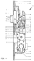
- Figure 1 is a plan view with a total of 1 designated main or lock housing shown, which on the side facing the viewer by means of a removed and therefore not shown in the drawing Cover is closed.
- a trap 2 Inside the case are a trap 2 and a latch 3 in the sense of the double arrow 4 can be moved.
- a follower 5 in the sense of Double arrow 6 rotatably mounted. She has a breakthrough 7, in particular a square opening, for receiving a Square mandrel of a pusher or other actuating element for the trap 2.
- a radially projecting approach 8 the Handle nut 5 is at the upper end of a slidable Intermediate piece 10, the lower end of the upper end a return spring (not shown) is assigned.
- a lock cylinder 22nd known type, for example a profile cylinder used.
- This lock cylinder 22 is by means of a the lock cylinder 22 inserted key 36 in the sense of the double arrow 24 is rotated about the geometric axis 45 and causes an intermediate gear, in particular a planetary gear 44 the rotation of a gear 23 and thereby pushing out or pulling back the latch 3.
- the Lock bit of the lock cylinder 22, not shown drives in this embodiment in a known manner slotted ring gear. Its rotational movement is over two Transfer idler gears to gear 23. This drives in known manner to a first control plate 25, via which first drive rods 42 and 43 up and down are driven.
- the gear 23 bears on its side facing the viewer Front a control cam 26 which when turning the Gear 23 a control edge 27 of a change lever 28 drives.
- This change lever 28 is a pin 29 in a link 30 provided in the first control plate 25 is guided and by means of a pin 31 on a second Control plate 32 articulated.
- This second control plate 32 is displaceable in the direction of the double arrow 9 Lock housing 1 stored.
- An elongated hole 33 is also provided on the change lever 28, in which engages a pin 34 of a link 35 which with the Control nut 17 is pivotally connected.
- the displacement of the change lever 28 described above the control cam 26 of the gear 23 also causes one Displacement of the handlebar 35, the pin 34 at the end of Elongated hole 33 is present.
- the displacement of the handlebar 35, the is articulated to the control nut 17, causes a rotation of the control nut 17 in the direction of the arrow 13, whereby, as also described above, the trap 2 over the end 18, which bears against the trap tail 20, is withdrawn. The door can then be opened.
- the follower 5 is activated by pressing Pusher not shown in the direction of arrow 40 around geometric axis 41 rotated. This causes a twist the control nut 17 in the same direction, i.e. in Clockwise direction, which over the end 18 which on the trap tail 20, the trap 2 in the direction of Arrow 14 is withdrawn.
- the handlebar 35 moved because it is articulated with the control nut washer 17th connected is.
- the pin 34 moves in the slot 33.
- the change lever 28 is taken along by the handlebar 35 not because the pin 34 from the change lever 28 via the slot 33 is uncoupled. The change lever 28 thus remains in its rest position shown in Figure 1 and Figure 3.
- a locking swivel lock which is in communication with the second drive rod 39 not operated so that the door is not fully opened can be, but only as far as this Locking swivel lock allows.
Landscapes
- Engineering & Computer Science (AREA)
- Mechanical Engineering (AREA)
- Lock And Its Accessories (AREA)
- Clamps And Clips (AREA)
- Memory System Of A Hierarchy Structure (AREA)
- Scissors And Nippers (AREA)
Abstract
Description
Die Erfindung betrifft ein Schloß, insbesondere ein
Einsteckschloß für eine Außentür, gemäß dem Oberbegriff des
Anspruchs 1.The invention relates to a lock, in particular a
Mortise lock for an outer door, according to the preamble of
Derartige Schlösser finden bei Haustüren oder Wohnungseingangstüren Verwendung, wobei sie bei der gebräuchlichsten Ausbildung als Einsteckschloß in eine Schloßtasche des Türblatts eingeschoben und über einen stirnseitig angebrachten Stulp oder dergleichen im Türblatt gehalten werden. Nach dem Anbringen dieses Einsteckschlosses an der Tür werden noch der oder die Türdrücker und ein Schließzylinder montiert. Im Falle einer Außentür befindet sich ein Türdrücker normalerweise nur an der Innenseite, während gegenüberliegend an der Außenseite ein sogenannter Knauf, d.h. ein nicht betätigbarer Griff montiert ist. Mit Hilfe des drehbaren Türdrückers kann die Falle zurückgezogen werden. Wenn sich der Riegel in seiner zurückgeschlossenen Stellung befindet, kann man bei zurückgezogener Falle die Tür öffnen. Sofern außen kein Türdrücker angebracht ist, läßt sich die Tür von außen nur mit Hilfe eines Schlüssels öffnen, über welchen die Falle ebenfalls zurückziehbar ist. Desweiteren läßt sich mit Hilfe des Schlüssels der Riegel sowohl von außen als auch von innen sowohl vorschließen als auch zurückschließen.Such locks can be found on front doors or Apartment entrance doors use, being at the most common training as a mortise lock in a Lock pocket of the door leaf inserted and over one faceplate or similar in the door leaf being held. After attaching this mortise lock at the door there are still door handles and one Lock cylinder mounted. In the case of an outside door a lever handle is usually only on the inside, while on the outside a so-called Knob, i.e. a handle that cannot be actuated is installed. With The latch can be withdrawn with the help of the rotating door handle become. When the bolt is closed in its Position, you can open the door when the latch is retracted to open. If there is no lever handle on the outside, you can only open the door from the outside using a key which the trap is also retractable. Furthermore can be locked with the help of the key both from the outside as well as lock from the inside as well back close.
Es sind auch Schlösser bekannt, welche nicht nur im Bereich des Schlosses oder Schloßkastens gegenüber dem festen Rahmen verriegelt werden, sondern mit Hilfe zusätzlicher Verriegelungseinrichtungen auch unterhalb und/oder oberhalb des eigentliches Schlosses bzw. des Schloßkastens. Diese in Zusatzriegelkästen vorgesehene Verriegelungseinrichtungen müssen gleichzeitig mit dem Riegel betätigbar sein, also in eine wirksame Stellung gebracht oder aus dieser in eine wirkungslose Stellung zurückgeführt werden können. Es sind desweiteren Schlösser bekannt, bei denen man den Riegel über den drehbaren Türdrücker in eine wirksame Stellung bzw. aus dieser in die Freigabestellung bringen kann, wobei der Drücker selbstverständlich auch hierbei zur Fallenbetätigung dient. Solche Schlösser gibt es sowohl mit als auch ohne zusätzliche Verriegelungseinrichtungen entlang zumindest der Schloßseite der Tür.There are also known locks, which are not only in the area of the lock or lock case opposite the fixed frame be locked, but with the help of additional Locking devices also below and / or above the actual lock or lock case. This in Additional locking boxes provided locking devices must be operable with the bolt at the same time, i.e. in brought into or out of an effective position ineffective position can be reduced. There are furthermore known locks, in which one latches on the rotary lever handle in an effective position or off can bring this into the release position, the pusher Of course, this also serves to operate the latch. Such locks are available both with and without additional ones Locking devices along at least the lock side the door.
Aus der DE 35 03 466 A1 ist ein Zusatzriegelkasten bekannt
geworden, welcher über eine Treibstange vom Hauptschloß
antreibbar ist. Dieses Hauptschloß kann z.B. gemäß der EP 575
701 A1 oder der DE 38 36 694 A1 ausgebildet sein. Bei einer derartigen
Verriegelungseinrichtung wird der Riegel mittels des
Schließzylinders ausgeschlossen und zurückgeschlossen. Die EP 0 575 701 A1 beschreibt ein Treibstangenschloß,
das dem Oberbegriff des Anspruchs 1 entspricht. Als
nachteilig hat sich jedoch herausgestellt, daß bei einem
Öffnen der Tür z.B. durch Betätigen des Türdrückers nicht nur
die Falle sondern auch der Riegel des Zusatzriegelkastens
betätigt und in die Freigabestellung verlagert werden, so daß
die Tür geöffnet werden kann. Es kann also kein vorschnelles
Öffnen der Tür, beispielsweise durch Kleinkinder, vermieden
werden, so daß ungebetene Personen unmittelbar Zutritt haben.An additional bolt box is known from
Der Erfindung liegt somit die Aufgabe zugrunde, eine Schließeinrichtung der eingangs genannten Art derart weiterzubilden, daß auch beim Öffnen der Tür mittels Betätigung des Hauptschloßkastens noch eine gewisse Sicherheit gegen vollständiges Öffnen gewährleistet ist.The invention is therefore based on the object Locking device of the type mentioned above to further develop that even when opening the door Actuation of the main lock case still a certain security is guaranteed against complete opening.
Diese Aufgabe wird bei einem Schloß der eingangs genannten Art erfindungsgemäß dadurch gelöst, daß zusätzlich zum Wechsel ein Wechselhebel vorgesehen ist, daß der Wechselhebel an einer zweiten Steuerplatte angelenkt ist und daß die Steuerplatte mit einer zweiten Treibstange z.B. für ein Sperrschwenkbügelschloß verbunden ist.This task is carried out in a castle of the type mentioned solved according to the invention in that in addition to the change Change lever is provided that the change lever on a second control plate is articulated and that the control plate with a second drive rod e.g. for a locking swivel lock connected is.
Beim erfindungsgemäßen Schloß kann zusätzlich zu den Zusatzriegelkästen z.B. noch ein Sperrschwenkbügelschloß vorgesehen sein, welches über eine zweite Treibstange betätigt wird. Diese zweite Treibstange wird von einer zweiten Steuerplatte angesteuert, die im Hauptschloß vorgesehen ist. Diese zweite Steuerplatte wird ihrerseits von einem Wechselhebel betätigt, der mit dem Wechsel verbunden ist. Auf diese Weise werden die Zusatzriegelkästen und das Sperrschwenkbügelschloß unabhängig voneinander mittels zweier Treibstangen betätigt. Auf diese Weise können die Zusatzriegelkästen so angesteuert werden, daß diese zusammen mit dem Hauptschloß öffnen, wohingegen das Sperrschwenkbügelschloß nach wie vor seine Sperrlage beibehält, d.h. der Sperriegel in seiner vorgeschlossenen Lage verbleibt. Erst durch separate Ansteuerung der zweiten Treibstange oder des Sperriegels über dessen Drehknauf wird dieser Riegel zurückgeschlossen, so daß die Tür vollständig geöffnet werden kann.In the lock according to the invention can in addition to Additional lock boxes e.g. another locking swivel lock be provided, which is actuated via a second drive rod becomes. This second drive rod is from a second Controlled control plate, which is provided in the main lock. This second control plate is in turn owned by one Change lever operated, which is connected to the change. On this way the additional lock boxes and that Locking swivel lock independently of one another by means of two Push rods actuated. That way they can Additional lock boxes are controlled so that they together open with the main lock, whereas that Locking swivel lock still its locking position maintains, i.e. the locking bolt in its pre-closed position remains. Only by separately controlling the second one Driving rod or the locking bolt is over the knob this bolt closed back so that the door completely can be opened.
Über den Steuernocken können sowohl der Wechsel als auch der Wechselhebel angesteuert werden. Both the change and the Change lever can be controlled.
Mit der erfindungsgemäßen Verriegelungseinrichtung kann die Tür zwar einen Spalt weit geöffnet werden, ein vollständiges Aufschwenken wird jedoch verhindert. Auf diese Weise wird auch ein versehentliches komplettes Öffnen bzw. Entriegeln der Tür verhindert.With the locking device according to the invention The door may be opened a crack, a complete one Swinging open is prevented. This way too an accidental complete opening or unlocking of the door prevented.
Bei einer Weiterbildung ist vorgesehen, daß der Wechselhebel mit dem Wechsel verbunden, insbesondere über eine Zapfen-Langloch-Verbindung mit dem gekoppelt ist. Diese Zapfen-Langloch-Verbindung erlaubt Relativbewegungen zwischen dem Wechselhebel und dem Hebel, so daß die Betätigung des einen nicht unmittelbar eine Betätigung des anderen verursachen muß.In a further development it is provided that the change lever connected with the change, in particular via a pin-slot connection with which is coupled. This pin-slot connection allows relative movements between the Change lever and the lever so that the actuation of one does not have to immediately cause the other to operate.
Gemäß einem bevorzugten Ausführungsbeispiel ist der Wechselhebel mit einem Langloch versehen, in welches ein Zapfen des Wechsels eingreift. Dabei liegt in der Ruhelage des Schlosses der Zapfen am einen Ende des Langloches an. Wird also der Wechselhebel in die eine Richtung bewegt, dann wird über den anliegenden Zapfen der Wechsel mitgenommen. Wird jedoch der Wechsel in die gleiche Richtung bewegt, dann läuft der Zapfen frei im Langloch, ohne daß der Wechselhebel betätigt wird.According to a preferred embodiment, the Change lever with an elongated hole in which a Pin of the change engages. It is in the rest position of the Connect the pin to one end of the slot. Becomes So the change lever moves in one direction, then the change taken over the adjacent pin. Becomes however the change moves in the same direction, then runs the pin freely in the slot without the change lever is operated.
Ein bevorzugtes Ausführungsbeispiel sieht vor, daß der Wechselhebel eine Steuerkante aufweist, an der ein Steuernocken eines mittels des Schließzylinders betätigbaren Getriebes, insbesondere eines Planetengetriebes angreift. Über dieses Planetengetriebe, welches durch Drehen eines Schlüssels betätigt wird, wird also der Wechselhebel im Schloß verlagert und dadurch die zweite Treibstange bewegt. Außerdem wird über den Wechselhebel der Wechsel betätigt, so daß über diesen die Falle eingezogen wird. Die Tür kann also von außen durch Betätigung eines Schlüssels geöffnet werden, wobei alle Schlösser in ihre Offenstellung bewegt werden.A preferred embodiment provides that the Change lever has a control edge on which a Control cam of an actuable by means of the lock cylinder Gearbox, especially a planetary gear attack. about this planetary gear, which is made by turning a key is actuated, the change lever is shifted in the lock and thereby moves the second drive rod. In addition, about the change lever operated the change, so that the Trap is drawn. So the door can go through from the outside Actuation of a key to be opened, all Locks are moved into their open position.
Die Zapfen-Langloch-Verbindung des Wechselhebels und des Wechsels ist so gewählt, daß beim Betätigen des Wechselhebels der Wechsel angetrieben wird, wohingegen beim Betätigen des Wechsels mittels der Drückernuß der Wechselhebel abgekoppelt ist. Ein Zurückschließen des Riegels des Sperrschwenkbügelschlosses ist also mittels des Drückers ausgeschlossen.The mortise and tenon connection of the change lever and the Change is selected so that when the change lever is actuated the change is driven, whereas when pressing the Alternating uncoupled by means of the follower of the change lever is. A closing of the bolt of the Locking swivel lock is therefore by means of the handle locked out.
In bekannter Art und Weise ist der Wechselhebel über eine Kulisse in einer ersten Steuerplatte geführt und ist aus dem Wirkbereich eines Planetengetriebes herauslenkbar. Auf diese Weise wird er erst beim Einziehen der Falle, jedoch nicht beim Zurückschließen des Riegels der Wechselhebel vom Planetengetriebe betätigt.In a known manner, the change lever is a Led in a first control plate and is from the Effective range of a planetary gear can be deflected out. To this He only becomes wise when the trap is pulled in, but not when Close the latch of the change lever from Planetary gear operated.
Als vorteilhaft wird angesehen, daß die zweite Steuerplatte in Richtung der zweiten Treibstange im Schloß verschiebbar gelagert ist. Die zweite Steuerplatte erstreckt sich parallel zur ersten Steuerplatte und besitzt lediglich die Funktion des Antriebs der zweiten Treibstange.It is considered advantageous that the second control plate in Slidable in the direction of the second drive rod in the lock is stored. The second control plate extends in parallel to the first control plate and only has the function of Drive the second drive rod.
Weitere Vorteile, Merkmale und Einzelheiten ergeben sich aus den Unteransprüchen sowie aus der nachfolgenden Beschreibung, in der unter Bezugnahme auf die Zeichnung ein besonders bevorzugtes Ausführungsbeispiel im einzelnen dargestellt ist. Dabei zeigen:
Figur 1- eine Draufsicht auf ein erfindungsgemäßes Einsteckschloß in Ruhelage und abgenommenem Deckel;
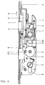
Figur 2- eine Draufsicht gemäß
Figur 1 mit betätigtem Schließzylinder; und Figur 3- eine Draufsicht gemäß
Figur 1 mit betätigter Drückernuß.
- Figure 1
- a plan view of a mortise lock according to the invention in the rest position and the cover removed;
- Figure 2
- a plan view of Figure 1 with the lock cylinder operated; and
- Figure 3
- a plan view of Figure 1 with the trigger nut actuated.
In der Figur 1 ist in Draufsicht ein insgesamt mit 1
bezeichnetes Haupt- oder Schloßgehäuse dargestellt, welches
auf der dem Betrachter zugewandten Seite mittels eines
abgenommenen und daher in der Zeichnung nicht dargestellten
Deckels verschlossen ist. Im Gehäuseinneren sind eine Falle 2
und ein Riegel 3 im Sinne des Doppelpfeils 4 verschiebbar.
Außerdem ist im Schloßgehäuse 1 eine Drückernuß 5 im Sinne des
Doppelpfeils 6 drehbar gelagert. Sie besitzt einen Durchbruch
7, insbesondere einen Vierkantdurchbruch, zur Aufnahme eines
Vierkantdorns eines Drückers oder anderen Betätigungselements
für die Falle 2. Ein radial vorstehender Ansatz 8 der
Drückernuß 5 liegt am oberen Ende eines verschiebbaren
Zwischenstücks 10 an, dessen unteres Ende dem oberen Ende
einer Rückstellfeder (nicht dargestellt) zugeordnet ist. Es
handelt sich dabei um eine Schraubendruckfeder, die mit ihrem
oberen Ende in einem Federgehäuse gehalten ist. Wenn man also
die Drückernuß 5 im Sinne des Pfeiles 13 dreht, so bewirkt
dies einerseits ein Zusammenpressen der Rückstellfeder und
andererseits ein Zurückziehen der Falle 2 im Sinne des Pfeils
14. Man erreicht dies dadurch, daß ein weiterer radial
vorstehender Ansatz 15 der Drücknuß 5 an einem zapfenartigen
Vorsprung 16 einer Steuernußscheibe 17 anliegt oder anlegbar
ist, welche an der Drückernuß 5 drehbar gelagert ist. Das
beispielsweise in Figur 1 nach oben weisende Ende 18 der
Steuernußscheibe 17 liegt an einer Schulter 19 des inneren
Endes der Falle 2 bzw. des Fallenschwanzes 20 an.In Figure 1 is a plan view with a total of 1
designated main or lock housing shown, which
on the side facing the viewer by means of a
removed and therefore not shown in the drawing
Cover is closed. Inside the case are a
In einen Durchbruch 21 am Boden des Schloßgehäuses 1 sowie am
nicht dargestellten Schloßdeckel ist ein Schließzylinder 22
bekannter Bauart, beispielsweise ein Profilzylinder
eingesetzt. Dieser Schließzylinder 22 wird mit Hilfe eines in
den Schließzylinder 22 eingesteckten Schlüssels 36 im Sinne
des Doppelpfeils 24 um die geometrische Achse 45 gedreht und
bewirkt über ein zwischengeschaltetes Getriebe, insbesondere
ein Planetengetriebe 44 die Verdrehung eines Zahnrades 23 und
dadurch ein Ausschieben bzw. Zurückziehen des Riegels 3. Der
nicht dargestellte Schließbart des Schließzylinders 22 treibt
bei dieser Ausführungsform in bekannter Weise einen
geschlitzten Zahnkranz an. Dessen Drehbewegung wird über zwei
Zwischenräder auf das Zahnrad 23 übertragen. Dieses treibt in
bekannter Weise eine erste Steuerplatte 25 an, über welche
erste Treibstangen 42 und 43 nach oben bzw. nach unten
angetrieben werden.In an
Das Zahnrad 23 trägt auf seiner dem Betrachter zugewandten
Stirnseite einen Steuernocken 26, der beim Verdrehen des
Zahnrades 23 eine Steuerkante 27 eines Wechselhebels 28
antreibt. Dieser Wechselhebel 28 ist über einen Zapfen 29 in
einer Kulisse 30, die in der ersten Steuerplatte 25 vorgesehen
ist, geführt und mittels eines Zapfens 31 an einer zweiten
Steuerplatte 32 gelenkig festgelegt. Diese zweite Steuerplatte
32 ist in Richtung des Doppelpfeils 9 verschieblich im
Schloßgehäuse 1 gelagert.The
Am Wechselhebel 28 ist außerdem ein Langloch 33 vorgesehen, in
welches ein Zapfen 34 eines Lenkers 35 eingreift, der mit der
Steuernußscheibe 17 schwenkbar verbunden ist.An
Wird wie in Figur 2 dargestellt, mittels eines Schlüssels 36
der Schließzylinder 22 in Richtung des Pfeils 37 betätigt,
dann greift der Steuernocken 26 an der Steuerkante 27 des
Wechselhebels 28 an und verlagert diesen nach oben, wodurch
die zweite Steuerplatte 32 in Richtung des Pfeils 38 nach oben
verschoben wird. An dieser zweiten Steuerplatte 32 ist eine
zweite Treibstange 39 befestigt, die von der zweiten
Steuerplatte 32 angetrieben wird. Über diese zweite
Treibstange 39 wird ein Sperrschwenkbügelschloß angetrieben,
insbesondere entriegelt. Diese Entriegelung erfolgt also dann,
wenn mittels eines Schlüssels 36 der Schließzylinder 22
betätigt wird.As shown in FIG. 2, using a key 36
the
Die oben beschriebene Verlagerung des Wechselhebels 28 über
den Steuernocken 26 des Zahnrads 23 bewirkt außerdem eine
Verschiebung des Lenkers 35, dessen Zapfen 34 am Endes des
Langlochs 33 anliegt. Die Verschiebung des Lenkers 35, der
gelenkig an der Steuernußscheibe 17 befestigt ist, bewirkt
eine Verdrehung der Steuernußscheibe 17 in Richtung des Pfeils
13, wodurch, wie ebenfalls weiter oben beschrieben, die Falle
2 über das Ende 18, welches am Fallenschwanz 20 anliegt,
zurückgezogen wird. Die Tür kann dann geöffnet werden.The displacement of the
In der Figur 3 wird die Drückernuß 5 durch Betätigen eines
nicht dargestellten Drückers in Richtung des Pfeils 40 um die
geometrische Achse 41 gedreht. Dies bewirkt eine Verdrehung
der Steuernußscheibe 17 in die gleiche Richtung, d.h. in
Richtung des Uhrzeigersinns, wodurch über das Ende 18, welches
am Fallenschwanz 20 anliegt, die Falle 2 in Richtung des
Pfeils 14 zurückgezogen wird. Außerdem wird der Lenker 35
verschoben, da dieser gelenkig mit der Steuernußscheibe 17
verbunden ist. Dabei verlagert sich der Zapfen 34 im Langloch
33. Eine Mitnahme des Wechselhebels 28 vom Lenker 35 erfolgt
nicht, da der Zapfen 34 vom Wechselhebel 28 über das Langloch
33 abgekoppelt ist. Der Wechselhebel 28 verharrt somit in
seiner in Figur 1 und Figur 3 gezeigten Ruhelage.In Figure 3, the
Wird also das Schloß 1 über einen Drücker betätigt, dann wird
lediglich die Falle 2 in Richtung des Pfeils 14 zurückgezogen,
jedoch nicht der Wechselhebel 28 bzw. über diesen die zweite
Treibstange 39 betätigt. Ein Sperrschwenkbügelschloß, welches
mit der zweiten Treibstange 39 in Verbindung steht, wird also
nicht betätigt, so daß die Tür nicht vollständig geöffnet
werden kann, sondern lediglich so weit, wie dies das
Sperrschwenkbügelschloß zuläßt.So if
Claims (10)
- A lock (1), in particular a mortise lock for an exterior door, having a latch bolt (2) and a further bolt (3) both arranged in a lock housing (19 for parallel displacement relative to said housing, said further bolt (3) being actuatable by a key (36) and the latch bolt (2) being actuatable either by a latch with a latch follower(5) or by a changer means (17, 35) via said key (36), further having an opening (21) for a lock cylinder (22), wherein the changer means (17, 35) is drivable by the bit of the lock cylinder (22) and having to drive rods arranged parallel to each other for activating further locking means, characterized in that in addition to the changer means (17, 35) a changer lever (28) is provided, that the changer lever (28) is hinged to said second control plate (32) and that the second control plate (32) is connected to said second drive rod (39) e.g. for a blocking pivot-shackle lock.
- The lock according to claim 1, characterized in that the changer lever (28) is connected to the changer means (17, 35) in particular via a bolt-hole-connection.
- The lock according to claim 2, characterized in that the changer lever (28) includes an elongated hole (33) engaged by a pin (34) of the changer means (17, 35), in particular of a guide rod (35).
- The lock according to claim 3, characterized in that the pin (34) rests on one end of said elongated hole (33) in the rest position of the lock.
- The lock according to one of the preceding claims, characterized in that said changer lever (28) has a control edge (27) being engaged by said control cam (26) of a gear means, in particular a planetary gear, actuatable by the lock cylinder (22).
- The lock according to one of the preceding claims, characterized in that actuation of said changer lever (28) produces actuation of said changer means (17, 35).
- The lock according to one of the preceding claims, characterized in that actuation of said changer means (17, 35) via the latch follower(5) the changer lever (28) is uncoupled.
- The lock according to one of the preceding claims, characterized in that the changer lever (28) is guided in a first control plate (25) via a connecting link (30) and that the changer lever (28) is guided out of range of action of the planetary gear (44).
- The lock according to one of the preceding claims, characterized in that the second control plate (32) is seated in the housing (1) displaceable in the direction of said second drive rod (39).
- The lock according to one of the preceding claims, characterized in that the changer means includes a guide rod (35) and a control follower disk (17) hingedly connected to the guide rod (35), and wherein in particular said control follower disk (17) is rotatably seated on said latch follower (5) and drivably connected to said latch bolt (2).
Applications Claiming Priority (2)
| Application Number | Priority Date | Filing Date | Title |
|---|---|---|---|
| DE29608862U DE29608862U1 (en) | 1996-05-17 | 1996-05-17 | Lock, especially mortise lock |
| DE29608862U | 1996-05-17 |
Publications (3)
| Publication Number | Publication Date |
|---|---|
| EP0807736A2 EP0807736A2 (en) | 1997-11-19 |
| EP0807736A3 EP0807736A3 (en) | 1998-03-11 |
| EP0807736B1 true EP0807736B1 (en) | 2002-11-20 |
Family
ID=8024058
Family Applications (1)
| Application Number | Title | Priority Date | Filing Date |
|---|---|---|---|
| EP97103818A Expired - Lifetime EP0807736B1 (en) | 1996-05-17 | 1997-04-03 | Mortise lock |
Country Status (4)
| Country | Link |
|---|---|
| US (1) | US5878605A (en) |
| EP (1) | EP0807736B1 (en) |
| AT (1) | ATE228196T1 (en) |
| DE (2) | DE29608862U1 (en) |
Families Citing this family (17)
| Publication number | Priority date | Publication date | Assignee | Title |
|---|---|---|---|---|
| DE29605517U1 (en) * | 1996-03-26 | 1997-07-24 | Gretsch-Unitas GmbH Baubeschläge, 71254 Ditzingen | Locking device |
| DE29719611U1 (en) * | 1997-11-05 | 1999-03-11 | Gretsch-Unitas GmbH Baubeschläge, 71254 Ditzingen | Lock, in particular mortise lock for an outer door |
| AT406496B (en) * | 1998-07-23 | 2000-05-25 | Roto Frank Eisenwaren | MULTI-LOCK LOCK |
| DE19855402C1 (en) * | 1998-12-01 | 2000-05-25 | Dorma Gmbh & Co Kg | Twin leaf fire door for building has flap, servo and locking strips mounted under common cover |
| US6282929B1 (en) * | 2000-02-10 | 2001-09-04 | Sargent Manufacturing Company | Multipoint mortise lock |
| AUPR604601A0 (en) * | 2001-06-29 | 2001-07-26 | Gainsborough Hardware Industries Limited | A mortice lock |
| US6871451B2 (en) | 2002-03-27 | 2005-03-29 | Newell Operating Company | Multipoint lock assembly |
| AT413125B (en) * | 2003-07-10 | 2005-11-15 | Roto Frank Eisenwaren | KEY OPERATED MULTIPLE LOCK |
| US7404306B2 (en) * | 2004-01-29 | 2008-07-29 | Newell Operating Company | Multi-point door lock and offset extension bolt assembly |
| US7946080B2 (en) | 2007-01-29 | 2011-05-24 | Newell Operating Company | Lock assembly |
| US8398126B2 (en) * | 2007-05-21 | 2013-03-19 | Truth Hardware Corporation | Multipoint lock mechanism |
| US7661279B2 (en) * | 2008-01-23 | 2010-02-16 | Door & Window Hardware Co. | Lock assembly |
| CA2681067C (en) * | 2008-10-03 | 2015-04-14 | Truth Hardware Corporation | Sliding door multipoint mortise lock with shoot bolts |
| US8550506B2 (en) * | 2009-06-30 | 2013-10-08 | Truth Hardware Corporation | Multi-point mortise lock mechanism for swinging door |
| US8875549B2 (en) | 2012-10-24 | 2014-11-04 | Door & Window Hardware Co. | Lock assembly |
| CA2895036C (en) | 2014-06-20 | 2022-09-20 | Truth Hardware Corporation | Recessed lock actuating device for sliding doors |
| AT14920U1 (en) * | 2015-02-19 | 2016-08-15 | Roto Frank Ag | lock |
Family Cites Families (13)
| Publication number | Priority date | Publication date | Assignee | Title |
|---|---|---|---|---|
| US4583382A (en) * | 1983-12-21 | 1986-04-22 | Schlage Lock Company | Reversible latch assembly with integrated function |
| FR2576628B1 (en) * | 1985-01-30 | 1989-06-30 | Grundmann Rohrbacher Schlosser | DOOR CLOSURE COMPRISING A LOCK WITH LOCK AND RACK AND A SECURITY LOCKING ELEMENT CONNECTED TO THE LOCK. |
| DE3505379C2 (en) * | 1985-02-16 | 1996-03-21 | Fliether Karl Gmbh & Co | Espagnolette lock |
| DE3543050A1 (en) * | 1985-12-05 | 1987-06-11 | Fuhr Carl Gmbh & Co | DRIVE ROD LOCK |
| WO1989002020A1 (en) * | 1987-09-04 | 1989-03-09 | Theodor Krachten | Lock with catch, safety bolt and catch locking slide |
| US5265920A (en) * | 1988-09-16 | 1993-11-30 | Aug. Winkaus GmbH & Co. KG | Drive rod lock |
| DE3844849C2 (en) * | 1988-09-16 | 1995-05-18 | Winkhaus Fa August | Espagnolette lock |
| DE3836694C2 (en) * | 1988-10-28 | 1996-05-09 | Fliether Karl Gmbh & Co | Espagnolette lock |
| FI83802C (en) * | 1988-11-25 | 1991-08-26 | Abloy Security Ltd Oy | ELEKTROMEKANISKT DOERRLAOS. |
| AT392819B (en) * | 1989-09-06 | 1991-06-25 | Evva Werke | LOCK, ESPECIALLY PANIC LOCK |
| DE4015880C2 (en) * | 1990-05-17 | 1999-01-07 | Wilka Schliestechnik Gmbh | Espagnolette lock |
| US5469723A (en) * | 1990-07-25 | 1995-11-28 | Litwin; Noel | Safety locks |
| DE9208526U1 (en) * | 1992-06-25 | 1992-09-10 | Gretsch-Unitas GmbH Baubeschläge, 7257 Ditzingen | Lock, especially mortise lock for an external door |
-
1996
- 1996-05-17 DE DE29608862U patent/DE29608862U1/en not_active Expired - Lifetime
-
1997
- 1997-04-03 DE DE59708746T patent/DE59708746D1/en not_active Expired - Fee Related
- 1997-04-03 EP EP97103818A patent/EP0807736B1/en not_active Expired - Lifetime
- 1997-04-03 AT AT97103818T patent/ATE228196T1/en not_active IP Right Cessation
- 1997-05-19 US US08/858,265 patent/US5878605A/en not_active Expired - Fee Related
Also Published As
| Publication number | Publication date |
|---|---|
| DE59708746D1 (en) | 2003-01-02 |
| US5878605A (en) | 1999-03-09 |
| EP0807736A2 (en) | 1997-11-19 |
| DE29608862U1 (en) | 1997-09-18 |
| ATE228196T1 (en) | 2002-12-15 |
| EP0807736A3 (en) | 1998-03-11 |
Similar Documents
| Publication | Publication Date | Title |
|---|---|---|
| DE102006059565B4 (en) | Locking system for doors, windows or the like, in particular espagnolette lock with panic function and multipoint locking | |
| EP0807736B1 (en) | Mortise lock | |
| EP2951369B1 (en) | Panic lock | |
| DE3447748C2 (en) | ||
| DE102006059568B4 (en) | Locking system for doors, windows or the like, in particular espagnolette lock with panic function and multipoint locking | |
| EP0796968B1 (en) | Closure device | |
| EP0521262B1 (en) | Lock | |
| EP0619409A1 (en) | Multiple bolt lock | |
| DE10024952A1 (en) | Lock driven by an electric motor | |
| EP0575701B1 (en) | Lock, in particular mortise lock for outer doors | |
| DE3425565A1 (en) | DRIVE ROD LOCK | |
| EP0141891B1 (en) | Espagnolette lock for doors, french doors or the like | |
| EP1260660A2 (en) | Actuation device for a lock bolt | |
| DE69403387T2 (en) | Lock for window or similar sash | |
| EP0485767B1 (en) | Lock for the wing, especially the sliding wing, of a window, door etc. | |
| EP3144455B1 (en) | Locking device | |
| DE4114007C2 (en) | Espagnolette lock | |
| EP0575660A2 (en) | Mortise lock for a house door or a flat entrance door | |
| EP2072725A2 (en) | Espagnolette locking device | |
| EP2339096A2 (en) | Connecting rod lock with panic function and multiple locking | |
| DE3831529C2 (en) | Espagnolette lock | |
| DE4431925C2 (en) | Lock for prison doors | |
| EP0974721B1 (en) | Lock with several bolts | |
| DE2605763C3 (en) | Espagnolette lock with latch | |
| DE3920498C2 (en) | Multiple locking |
Legal Events
| Date | Code | Title | Description |
|---|---|---|---|
| PUAI | Public reference made under article 153(3) epc to a published international application that has entered the european phase |
Free format text: ORIGINAL CODE: 0009012 |
|
| AK | Designated contracting states |
Kind code of ref document: A2 Designated state(s): AT BE DE FR GB IT NL |
|
| PUAL | Search report despatched |
Free format text: ORIGINAL CODE: 0009013 |
|
| AK | Designated contracting states |
Kind code of ref document: A3 Designated state(s): AT BE DE FR GB IT NL |
|
| 17P | Request for examination filed |
Effective date: 19980403 |
|
| GRAG | Despatch of communication of intention to grant |
Free format text: ORIGINAL CODE: EPIDOS AGRA |
|
| GRAG | Despatch of communication of intention to grant |
Free format text: ORIGINAL CODE: EPIDOS AGRA |
|
| 17Q | First examination report despatched |
Effective date: 20001215 |
|
| GRAG | Despatch of communication of intention to grant |
Free format text: ORIGINAL CODE: EPIDOS AGRA |
|
| GRAH | Despatch of communication of intention to grant a patent |
Free format text: ORIGINAL CODE: EPIDOS IGRA |
|
| GRAH | Despatch of communication of intention to grant a patent |
Free format text: ORIGINAL CODE: EPIDOS IGRA |
|
| GRAA | (expected) grant |
Free format text: ORIGINAL CODE: 0009210 |
|
| AK | Designated contracting states |
Kind code of ref document: B1 Designated state(s): AT BE DE FR GB IT NL |
|
| REF | Corresponds to: |
Ref document number: 228196 Country of ref document: AT Date of ref document: 20021215 Kind code of ref document: T |
|
| REG | Reference to a national code |
Ref country code: GB Ref legal event code: FG4D Free format text: NOT ENGLISH |
|
| GBT | Gb: translation of ep patent filed (gb section 77(6)(a)/1977) |
Effective date: 20021120 |
|
| REF | Corresponds to: |
Ref document number: 59708746 Country of ref document: DE Date of ref document: 20030102 |
|
| ET | Fr: translation filed | ||
| PLBE | No opposition filed within time limit |
Free format text: ORIGINAL CODE: 0009261 |
|
| STAA | Information on the status of an ep patent application or granted ep patent |
Free format text: STATUS: NO OPPOSITION FILED WITHIN TIME LIMIT |
|
| PG25 | Lapsed in a contracting state [announced via postgrant information from national office to epo] |
Ref country code: NL Free format text: LAPSE BECAUSE OF NON-PAYMENT OF DUE FEES Effective date: 20031101 |
|
| 26N | No opposition filed |
Effective date: 20030821 |
|
| NLV4 | Nl: lapsed or anulled due to non-payment of the annual fee |
Effective date: 20031101 |
|
| PGFP | Annual fee paid to national office [announced via postgrant information from national office to epo] |
Ref country code: GB Payment date: 20050322 Year of fee payment: 9 |
|
| PGFP | Annual fee paid to national office [announced via postgrant information from national office to epo] |
Ref country code: FR Payment date: 20050412 Year of fee payment: 9 |
|
| PGFP | Annual fee paid to national office [announced via postgrant information from national office to epo] |
Ref country code: AT Payment date: 20050414 Year of fee payment: 9 |
|
| PGFP | Annual fee paid to national office [announced via postgrant information from national office to epo] |
Ref country code: BE Payment date: 20050509 Year of fee payment: 9 |
|
| PG25 | Lapsed in a contracting state [announced via postgrant information from national office to epo] |
Ref country code: GB Free format text: LAPSE BECAUSE OF NON-PAYMENT OF DUE FEES Effective date: 20060403 Ref country code: AT Free format text: LAPSE BECAUSE OF NON-PAYMENT OF DUE FEES Effective date: 20060403 |
|
| PG25 | Lapsed in a contracting state [announced via postgrant information from national office to epo] |
Ref country code: BE Free format text: LAPSE BECAUSE OF NON-PAYMENT OF DUE FEES Effective date: 20060430 |
|
| PGFP | Annual fee paid to national office [announced via postgrant information from national office to epo] |
Ref country code: IT Payment date: 20060430 Year of fee payment: 10 |
|
| GBPC | Gb: european patent ceased through non-payment of renewal fee |
Effective date: 20060403 |
|
| REG | Reference to a national code |
Ref country code: FR Ref legal event code: ST Effective date: 20061230 |
|
| BERE | Be: lapsed |
Owner name: *GRETSCH-UNITAS G.M.B.H. BAUBESCHLAGE Effective date: 20060430 |
|
| PG25 | Lapsed in a contracting state [announced via postgrant information from national office to epo] |
Ref country code: FR Free format text: LAPSE BECAUSE OF NON-PAYMENT OF DUE FEES Effective date: 20060502 |
|
| PGFP | Annual fee paid to national office [announced via postgrant information from national office to epo] |
Ref country code: DE Payment date: 20080418 Year of fee payment: 12 |
|
| PG25 | Lapsed in a contracting state [announced via postgrant information from national office to epo] |
Ref country code: IT Free format text: LAPSE BECAUSE OF NON-PAYMENT OF DUE FEES Effective date: 20070403 |
|
| PG25 | Lapsed in a contracting state [announced via postgrant information from national office to epo] |
Ref country code: DE Free format text: LAPSE BECAUSE OF NON-PAYMENT OF DUE FEES Effective date: 20091103 |