EP0807722A2 - Fixation pour isolation thermique - Google Patents
Fixation pour isolation thermique Download PDFInfo
- Publication number
- EP0807722A2 EP0807722A2 EP97810206A EP97810206A EP0807722A2 EP 0807722 A2 EP0807722 A2 EP 0807722A2 EP 97810206 A EP97810206 A EP 97810206A EP 97810206 A EP97810206 A EP 97810206A EP 0807722 A2 EP0807722 A2 EP 0807722A2
- Authority
- EP
- European Patent Office
- Prior art keywords
- head
- cover
- pin
- hollow shaft
- opening
- Prior art date
- Legal status (The legal status is an assumption and is not a legal conclusion. Google has not performed a legal analysis and makes no representation as to the accuracy of the status listed.)
- Granted
Links
- 238000009413 insulation Methods 0.000 title claims abstract description 10
- 239000011538 cleaning material Substances 0.000 description 8
- 239000000463 material Substances 0.000 description 2
- 239000011505 plaster Substances 0.000 description 2
- 230000007797 corrosion Effects 0.000 description 1
- 238000005260 corrosion Methods 0.000 description 1
- 230000007423 decrease Effects 0.000 description 1
- 230000003993 interaction Effects 0.000 description 1
- 238000004519 manufacturing process Methods 0.000 description 1
Images

Classifications
-
- E—FIXED CONSTRUCTIONS
- E04—BUILDING
- E04B—GENERAL BUILDING CONSTRUCTIONS; WALLS, e.g. PARTITIONS; ROOFS; FLOORS; CEILINGS; INSULATION OR OTHER PROTECTION OF BUILDINGS
- E04B1/00—Constructions in general; Structures which are not restricted either to walls, e.g. partitions, or floors or ceilings or roofs
- E04B1/62—Insulation or other protection; Elements or use of specified material therefor
- E04B1/74—Heat, sound or noise insulation, absorption, or reflection; Other building methods affording favourable thermal or acoustical conditions, e.g. accumulating of heat within walls
- E04B1/76—Heat, sound or noise insulation, absorption, or reflection; Other building methods affording favourable thermal or acoustical conditions, e.g. accumulating of heat within walls specifically with respect to heat only
- E04B1/762—Exterior insulation of exterior walls
- E04B1/7629—Details of the mechanical connection of the insulation to the wall
- E04B1/7633—Dowels with enlarged insulation retaining head
-
- E—FIXED CONSTRUCTIONS
- E04—BUILDING
- E04F—FINISHING WORK ON BUILDINGS, e.g. STAIRS, FLOORS
- E04F13/00—Coverings or linings, e.g. for walls or ceilings
- E04F13/07—Coverings or linings, e.g. for walls or ceilings composed of covering or lining elements; Sub-structures therefor; Fastening means therefor
- E04F13/08—Coverings or linings, e.g. for walls or ceilings composed of covering or lining elements; Sub-structures therefor; Fastening means therefor composed of a plurality of similar covering or lining elements
- E04F13/0801—Separate fastening elements
- E04F13/0832—Separate fastening elements without load-supporting elongated furring elements between wall and covering elements
- E04F13/0833—Separate fastening elements without load-supporting elongated furring elements between wall and covering elements not adjustable
- E04F13/0835—Separate fastening elements without load-supporting elongated furring elements between wall and covering elements not adjustable the fastening elements extending into the back side of the covering elements
-
- Y—GENERAL TAGGING OF NEW TECHNOLOGICAL DEVELOPMENTS; GENERAL TAGGING OF CROSS-SECTIONAL TECHNOLOGIES SPANNING OVER SEVERAL SECTIONS OF THE IPC; TECHNICAL SUBJECTS COVERED BY FORMER USPC CROSS-REFERENCE ART COLLECTIONS [XRACs] AND DIGESTS
- Y10—TECHNICAL SUBJECTS COVERED BY FORMER USPC
- Y10S—TECHNICAL SUBJECTS COVERED BY FORMER USPC CROSS-REFERENCE ART COLLECTIONS [XRACs] AND DIGESTS
- Y10S411/00—Expanded, threaded, driven, headed, tool-deformed, or locked-threaded fastener
- Y10S411/904—Fastener or fastener element composed of nonmetallic material
- Y10S411/908—Resinous material
Definitions
- the invention relates to a device for fastening insulation elements to a component, according to the preamble of patent claim 1.
- Plaster material is applied to the insulation elements. It is important that no cleaning material can get into the interior of the hollow shaft, as this leads to depressions on the surface of the applied layer of plaster. If cleaning material and thus moisture penetrates into the interior of the hollow shaft, this can cause corrosion on the fastening element if it is not made of rustproof material.
- the opening can be closed by means of a cover.
- This cover is arranged on the large-area head so as to be pivotable about an articulation axis and, in the closed position, cooperates with a projection which protrudes from the inner wall of the hollow shaft, which runs parallel to the longitudinal axis of the hollow shaft. In the closed position, the cover, with its side pointing counter to the setting direction, lies against the stop edge of the projection facing the interior.
- the cover When closing the opening or when applying cleaning material, the cover can be pressed or pivoted so far into the interior that the opening is no longer closed and cleaning material can thus get into the interior of the hollow shaft.
- the invention has for its object to provide a device for attaching insulation elements, in which it is ensured that the force of forces caused by the handling or application of cleaning material, the lid remains securely closed.
- the surface running parallel to the cross-sectional area of the hollow shaft, on which the projection is arranged, serves as a stop surface for the cover so that it cannot be pressed further into the interior of the hollow shaft from the closed position.
- the arrangement of the projection on the stop surface enables simple and safe interaction with the cover when it is moved into the closed position.
- the surface is preferably formed by a bottom at least partially surrounding the opening of a recess arranged in the head and receiving the cover in the closed position.
- the projection arranged on the bottom is expediently designed as a pin projecting essentially perpendicularly from the bottom, which can be snapped into a through hole arranged on the cover.
- An inseparable connection between the pin and the cover is advantageously achieved by the pin widening stepwise against the setting direction and tapering conically towards its free end, the largest diameter of the pin being larger than the diameter of the through hole.
- the wall thickness of the cover cooperating with the pin can correspond, for example, at least in the area of the through hole to the distance between the step of the step-like expansion and the bottom of the depression.
- the cover is expediently formed in two parts, the cover parts being articulated outside the opening and pivotable about joint axes running parallel to one another.
- the sides of the cover parts facing each other in the open position serve as a centering aid when inserting the tool.
- the sides of the cover parts pointing counter to the setting direction can, for example, be provided with a profile which ensures better adhesion of the cleaning material. Better adhesion also means that tensile forces can act on the cover parts. So that these cover parts remain securely in the closed position even when tensile forces occur, at least two pegs are preferably arranged on the base and each cover part has at least one through hole into which a peg can be latched.
- Both cover parts can therefore also be pivoted into the closed position at the same time.
- the device shown in Fig. 1 is used to attach insulation elements, not shown, to a component, also not shown, and is composed of a large-area head 1 and a hollow shaft 2 adjoining it.
- the hollow shaft 2 has an inner space 4 which is accessible from the outside through an opening 15 arranged in the area of the large-area head 1 and which serves to accommodate a fastening element 3 with which the device can be fixed to the component.
- An arranged in the interior 4 of the hollow shaft 2, against the Stop face 5 pointing in the direction of setting serves as an abutment for a radially widened region 6 of the fastening element 3.
- the opening 15 can be closed by means of two cover parts 7, 8 of a cover, which in the closed position have a depression 13 in the bottom 14 of the head 1 are arranged sunk.
- Two through bores 9, 10 of each cover part 7, 8 each act together with two pins 11, 12 projecting from the bottom 13.
- Both cover parts 7, 8 are arranged on the large-area head 1 so as to be pivotable about hinge axes 16, 17 lying outside the opening 15.
- the projection surface of the depression 14 extends around the opening 15 and has a substantially square shape.
- the hinge axes 16, 17 extend along two mutually opposite sides of this recess 14.
- the length of the cover parts 7, 8 measured parallel to the hinge axis 16, 17 essentially corresponds to a side length of the recess 14.
- the length of the cover parts measured perpendicular to the hinge axis 16, 17 7, 8 corresponds essentially to half the side length of the recess 14.
- the wall thickness of the cover parts 7, 8 is essentially matched to the depth of the recess 14.
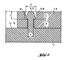
- FIG. 2 shows the enlarged representation of a through bore 9, 10 which interacts with a pin 11, 12.
- This through hole 9, 10 is of stepped design, the largest diameter of the through hole 9, 10 being arranged in the region of the large-area head 1 pointing counter to the setting direction.
- the pin 11, 12 projecting essentially vertically from the bottom 13 of the recess 14 has a step-like extension 18, which in turn tapers conically towards the free end of the pin 11, 12.
- the distance A between the step of the step-like extension 18 and the bottom 13, from which the pin 11, 12 protrudes corresponds essentially to the wall thickness of the cover parts 7, 8, reduced by the depth T of that area of the through hole 9, 10 with the larger one Diameter.
- the tapering region of the pin 11, 12 extends over a length L, which essentially corresponds to the depth T of that region of the through hole 9, 10 which has the larger diameter.
- the closest diameter D of the pin 11, 12 is larger than that part of the through hole 9, 10 with the smaller diameter d.
- the wall thickness of the large-area head 1 decreases towards its outer contour.
Landscapes
- Engineering & Computer Science (AREA)
- Architecture (AREA)
- Structural Engineering (AREA)
- Civil Engineering (AREA)
- Physics & Mathematics (AREA)
- Acoustics & Sound (AREA)
- Electromagnetism (AREA)
- Connection Of Plates (AREA)
- Insulators (AREA)
- Insulating Bodies (AREA)
- Insertion Pins And Rivets (AREA)
- Portable Nailing Machines And Staplers (AREA)
- Multi-Conductor Connections (AREA)
Applications Claiming Priority (2)
| Application Number | Priority Date | Filing Date | Title |
|---|---|---|---|
| DE19619318A DE19619318A1 (de) | 1996-05-14 | 1996-05-14 | Dämmstoffbefestigungselement |
| DE19619318 | 1996-05-14 |
Publications (3)
| Publication Number | Publication Date |
|---|---|
| EP0807722A2 true EP0807722A2 (fr) | 1997-11-19 |
| EP0807722A3 EP0807722A3 (fr) | 2000-08-02 |
| EP0807722B1 EP0807722B1 (fr) | 2003-06-18 |
Family
ID=7794224
Family Applications (1)
| Application Number | Title | Priority Date | Filing Date |
|---|---|---|---|
| EP97810206A Expired - Lifetime EP0807722B1 (fr) | 1996-05-14 | 1997-04-09 | Fixation pour isolation thermique |
Country Status (5)
| Country | Link |
|---|---|
| US (1) | US5779421A (fr) |
| EP (1) | EP0807722B1 (fr) |
| AT (1) | ATE243288T1 (fr) |
| CA (1) | CA2204938C (fr) |
| DE (2) | DE19619318A1 (fr) |
Cited By (3)
| Publication number | Priority date | Publication date | Assignee | Title |
|---|---|---|---|---|
| EP0959198A1 (fr) * | 1998-05-18 | 1999-11-24 | Berner GmbH | Support pour panneaux isolants |
| EP1050690A3 (fr) * | 1999-05-07 | 2002-04-17 | HILTI Aktiengesellschaft | Dispositif de fixation pour panneaux isolants |
| RU172001U1 (ru) * | 2017-01-30 | 2017-06-26 | Виталий Евгеньевич Чекалин | Крепежный элемент обрешетки |
Families Citing this family (6)
| Publication number | Priority date | Publication date | Assignee | Title |
|---|---|---|---|---|
| US6513301B1 (en) | 1999-10-20 | 2003-02-04 | Robert Snyder | Method of and instrument or arrangement for installing thermal insulation sheets in confined areas |
| CA2573067C (fr) * | 2004-07-19 | 2015-04-21 | James Murtha | Adaptateur de profondeur et doigtier preregles pour vis et clous lors de l'installation d'une plaque de platre |
| DE202007010563U1 (de) | 2007-07-27 | 2007-11-15 | Kew Kunststofferzeugnisse Gmbh Wilthen | Befestigungselement |
| DE102008041036A1 (de) * | 2008-08-06 | 2010-02-11 | Hilti Aktiengesellschaft | Nagelförmiges Befestigungselement |
| KR101077844B1 (ko) * | 2011-04-29 | 2011-11-07 | 김재옥 | 건축용 석재 받침앵글의 지지장치 |
| US10228007B2 (en) * | 2015-12-09 | 2019-03-12 | Illinois Tool Works Inc. | Panel fastener |
Family Cites Families (10)
| Publication number | Priority date | Publication date | Assignee | Title |
|---|---|---|---|---|
| DE3045986C2 (de) * | 1980-12-05 | 1985-04-04 | Adolf Böhl Schrauben- und Kunststoffwerk GmbH & Co, 5920 Bad Berleburg | Befestigungselement für die Befestigung von wärmeisolierenden Platten |
| DE3244839A1 (de) * | 1982-12-03 | 1984-06-07 | Achim Ing.(grad.) 8000 München Hirsemann | Daemmstoffhalter |
| US4884932A (en) * | 1987-05-01 | 1989-12-05 | Meyer Eugene M | Decking insulation fastener |
| DE4041819A1 (de) * | 1990-12-24 | 1992-06-25 | Hilti Ag | Befestigungselement fuer isolationsplatten |
| US5118235A (en) * | 1991-02-11 | 1992-06-02 | Illinois Tool Works Inc. | Washer with integral flap and fastening assembly combining fastener with such washer |
| DE9311122U1 (de) * | 1993-07-26 | 1993-10-07 | EJOT Kunststofftechnik GmbH & Co KG, 57319 Bad Berleburg | Befestigungselement und Setzgerät für ein solches Befestigungselement |
| DE4343030C2 (de) * | 1993-12-16 | 1998-07-16 | Toge Duebel A Gerhard Kg | Isolierdorn-Dübel aus Metall |
| US5607272A (en) * | 1995-01-06 | 1997-03-04 | Illinois Tool Works Inc. | Attachment plate for insulation panels |
| DE19504463A1 (de) * | 1995-02-10 | 1996-08-14 | Hilti Ag | Befestigungselement für Isolationsmaterialien |
| US5626451A (en) * | 1995-10-12 | 1997-05-06 | Wind-Lock Corporation | Washer for use with exterior insulation |
-
1996
- 1996-05-14 DE DE19619318A patent/DE19619318A1/de not_active Ceased
-
1997
- 1997-04-09 DE DE59710293T patent/DE59710293D1/de not_active Expired - Lifetime
- 1997-04-09 AT AT97810206T patent/ATE243288T1/de active
- 1997-04-09 EP EP97810206A patent/EP0807722B1/fr not_active Expired - Lifetime
- 1997-05-09 CA CA002204938A patent/CA2204938C/fr not_active Expired - Fee Related
- 1997-05-13 US US08/855,348 patent/US5779421A/en not_active Expired - Lifetime
Cited By (3)
| Publication number | Priority date | Publication date | Assignee | Title |
|---|---|---|---|---|
| EP0959198A1 (fr) * | 1998-05-18 | 1999-11-24 | Berner GmbH | Support pour panneaux isolants |
| EP1050690A3 (fr) * | 1999-05-07 | 2002-04-17 | HILTI Aktiengesellschaft | Dispositif de fixation pour panneaux isolants |
| RU172001U1 (ru) * | 2017-01-30 | 2017-06-26 | Виталий Евгеньевич Чекалин | Крепежный элемент обрешетки |
Also Published As
| Publication number | Publication date |
|---|---|
| ATE243288T1 (de) | 2003-07-15 |
| EP0807722A3 (fr) | 2000-08-02 |
| US5779421A (en) | 1998-07-14 |
| DE59710293D1 (de) | 2003-07-24 |
| CA2204938C (fr) | 2001-10-30 |
| CA2204938A1 (fr) | 1997-11-14 |
| EP0807722B1 (fr) | 2003-06-18 |
| DE19619318A1 (de) | 1997-11-20 |
Similar Documents
| Publication | Publication Date | Title |
|---|---|---|
| DE19603285A1 (de) | Intramedullärer Nagel | |
| DE3833040C2 (fr) | ||
| EP3526476B1 (fr) | Clip à montage flottant | |
| DE2610200C3 (de) | Beschlag zum lösbaren Verbinden zweier Bauteile, insbesondere von plattenförmigen Bauteilen für Möbel | |
| DE29916682U1 (de) | Anordnung zur Sicherung eines Bauteils | |
| EP0807722A2 (fr) | Fixation pour isolation thermique | |
| DE3305272C2 (fr) | ||
| EP0539687A1 (fr) | Joint perpendiculaire pour des profilés avec des rainures longitudinales | |
| EP0919733B1 (fr) | Cheville de fixation pour éléments de garniture pour meubles | |
| DE69828298T2 (de) | Vorrichtungen zum herstellen einer verbindung | |
| DE2656958B2 (de) | Eckverbindung von auf Gehrung geschnittenen Profilen eines Fensterrahmens, Türrahmens o.dgl | |
| DE3346067C2 (fr) | ||
| WO2021052840A1 (fr) | Élément de fixation et agencement de composant doté d'un élément de fixation et procédé de fixation | |
| DE2834432A1 (de) | Schnellbefestigung | |
| EP2148099B1 (fr) | Élément d'ancrage | |
| DE10223383A1 (de) | Gehäuse mit Rastvorrichtung zur Befestigung an einer Trägerplatte | |
| EP0297053A1 (fr) | Assemblage à cheville | |
| DE9316475U1 (de) | Ringschraube | |
| EP0454940B1 (fr) | Dispositif d'assemblage de cadre et montant de rive | |
| DE19629180B4 (de) | Dämmstoffbefestigungselement | |
| DE868810C (de) | Nageltuelle zum Abbiegen der Spitze des Nagels beim Einschlagen | |
| DE102009010832B4 (de) | Montagevorrichtung und Montageverfahren für Tür- und/oder Fensterzargen | |
| EP0801234A1 (fr) | Cheville expansible, notamment pour fixer de panneaux isolants sur maçonnerie | |
| DE19629179B4 (de) | Dämmstoffbefestigungselement | |
| DE4410793A1 (de) | Nagel mit einem Spreizbereich |
Legal Events
| Date | Code | Title | Description |
|---|---|---|---|
| PUAI | Public reference made under article 153(3) epc to a published international application that has entered the european phase |
Free format text: ORIGINAL CODE: 0009012 |
|
| AK | Designated contracting states |
Kind code of ref document: A2 Designated state(s): AT DE FR GB NL |
|
| PUAL | Search report despatched |
Free format text: ORIGINAL CODE: 0009013 |
|
| AK | Designated contracting states |
Kind code of ref document: A3 Designated state(s): AT DE FR GB NL |
|
| 17P | Request for examination filed |
Effective date: 20010202 |
|
| GRAH | Despatch of communication of intention to grant a patent |
Free format text: ORIGINAL CODE: EPIDOS IGRA |
|
| RTI1 | Title (correction) |
Free format text: INSULATION FIXING MEANS |
|
| GRAH | Despatch of communication of intention to grant a patent |
Free format text: ORIGINAL CODE: EPIDOS IGRA |
|
| GRAA | (expected) grant |
Free format text: ORIGINAL CODE: 0009210 |
|
| AK | Designated contracting states |
Designated state(s): AT DE FR GB NL |
|
| REG | Reference to a national code |
Ref country code: GB Ref legal event code: FG4D Free format text: NOT ENGLISH |
|
| REF | Corresponds to: |
Ref document number: 59710293 Country of ref document: DE Date of ref document: 20030724 Kind code of ref document: P |
|
| GBT | Gb: translation of ep patent filed (gb section 77(6)(a)/1977) |
Effective date: 20031021 |
|
| ET | Fr: translation filed | ||
| PLBE | No opposition filed within time limit |
Free format text: ORIGINAL CODE: 0009261 |
|
| STAA | Information on the status of an ep patent application or granted ep patent |
Free format text: STATUS: NO OPPOSITION FILED WITHIN TIME LIMIT |
|
| 26N | No opposition filed |
Effective date: 20040319 |
|
| PGFP | Annual fee paid to national office [announced via postgrant information from national office to epo] |
Ref country code: AT Payment date: 20120327 Year of fee payment: 16 |
|
| PGFP | Annual fee paid to national office [announced via postgrant information from national office to epo] |
Ref country code: DE Payment date: 20130314 Year of fee payment: 17 Ref country code: GB Payment date: 20130403 Year of fee payment: 17 |
|
| PGFP | Annual fee paid to national office [announced via postgrant information from national office to epo] |
Ref country code: FR Payment date: 20130625 Year of fee payment: 17 Ref country code: NL Payment date: 20130410 Year of fee payment: 17 |
|
| REG | Reference to a national code |
Ref country code: DE Ref legal event code: R119 Ref document number: 59710293 Country of ref document: DE |
|
| REG | Reference to a national code |
Ref country code: NL Ref legal event code: V1 Effective date: 20141101 |
|
| REG | Reference to a national code |
Ref country code: AT Ref legal event code: MM01 Ref document number: 243288 Country of ref document: AT Kind code of ref document: T Effective date: 20140409 |
|
| GBPC | Gb: european patent ceased through non-payment of renewal fee |
Effective date: 20140409 |
|
| REG | Reference to a national code |
Ref country code: FR Ref legal event code: ST Effective date: 20141231 |
|
| REG | Reference to a national code |
Ref country code: DE Ref legal event code: R119 Ref document number: 59710293 Country of ref document: DE Effective date: 20141101 |
|
| PG25 | Lapsed in a contracting state [announced via postgrant information from national office to epo] |
Ref country code: DE Free format text: LAPSE BECAUSE OF NON-PAYMENT OF DUE FEES Effective date: 20141101 Ref country code: GB Free format text: LAPSE BECAUSE OF NON-PAYMENT OF DUE FEES Effective date: 20140409 |
|
| PG25 | Lapsed in a contracting state [announced via postgrant information from national office to epo] |
Ref country code: AT Free format text: LAPSE BECAUSE OF NON-PAYMENT OF DUE FEES Effective date: 20140409 Ref country code: NL Free format text: LAPSE BECAUSE OF NON-PAYMENT OF DUE FEES Effective date: 20141101 Ref country code: FR Free format text: LAPSE BECAUSE OF NON-PAYMENT OF DUE FEES Effective date: 20140430 |