EP0807507B1 - Schnelles Spritzgiessen von Kabelbindern - Google Patents
Schnelles Spritzgiessen von Kabelbindern Download PDFInfo
- Publication number
- EP0807507B1 EP0807507B1 EP97113656A EP97113656A EP0807507B1 EP 0807507 B1 EP0807507 B1 EP 0807507B1 EP 97113656 A EP97113656 A EP 97113656A EP 97113656 A EP97113656 A EP 97113656A EP 0807507 B1 EP0807507 B1 EP 0807507B1
- Authority
- EP
- European Patent Office
- Prior art keywords
- head
- mold part
- cable tie
- mold
- strap
- Prior art date
- Legal status (The legal status is an assumption and is not a legal conclusion. Google has not performed a legal analysis and makes no representation as to the accuracy of the status listed.)
- Expired - Lifetime
Links
Images
Classifications
-
- B—PERFORMING OPERATIONS; TRANSPORTING
- B29—WORKING OF PLASTICS; WORKING OF SUBSTANCES IN A PLASTIC STATE IN GENERAL
- B29C—SHAPING OR JOINING OF PLASTICS; SHAPING OF MATERIAL IN A PLASTIC STATE, NOT OTHERWISE PROVIDED FOR; AFTER-TREATMENT OF THE SHAPED PRODUCTS, e.g. REPAIRING
- B29C33/00—Moulds or cores; Details thereof or accessories therefor
- B29C33/44—Moulds or cores; Details thereof or accessories therefor with means for, or specially constructed to facilitate, the removal of articles, e.g. of undercut articles
- B29C33/46—Moulds or cores; Details thereof or accessories therefor with means for, or specially constructed to facilitate, the removal of articles, e.g. of undercut articles using fluid pressure
-
- B—PERFORMING OPERATIONS; TRANSPORTING
- B29—WORKING OF PLASTICS; WORKING OF SUBSTANCES IN A PLASTIC STATE IN GENERAL
- B29C—SHAPING OR JOINING OF PLASTICS; SHAPING OF MATERIAL IN A PLASTIC STATE, NOT OTHERWISE PROVIDED FOR; AFTER-TREATMENT OF THE SHAPED PRODUCTS, e.g. REPAIRING
- B29C45/00—Injection moulding, i.e. forcing the required volume of moulding material through a nozzle into a closed mould; Apparatus therefor
- B29C45/17—Component parts, details or accessories; Auxiliary operations
- B29C45/40—Removing or ejecting moulded articles
-
- B—PERFORMING OPERATIONS; TRANSPORTING
- B29—WORKING OF PLASTICS; WORKING OF SUBSTANCES IN A PLASTIC STATE IN GENERAL
- B29C—SHAPING OR JOINING OF PLASTICS; SHAPING OF MATERIAL IN A PLASTIC STATE, NOT OTHERWISE PROVIDED FOR; AFTER-TREATMENT OF THE SHAPED PRODUCTS, e.g. REPAIRING
- B29C45/00—Injection moulding, i.e. forcing the required volume of moulding material through a nozzle into a closed mould; Apparatus therefor
- B29C45/17—Component parts, details or accessories; Auxiliary operations
- B29C45/40—Removing or ejecting moulded articles
- B29C45/43—Removing or ejecting moulded articles using fluid under pressure
-
- B—PERFORMING OPERATIONS; TRANSPORTING
- B29—WORKING OF PLASTICS; WORKING OF SUBSTANCES IN A PLASTIC STATE IN GENERAL
- B29C—SHAPING OR JOINING OF PLASTICS; SHAPING OF MATERIAL IN A PLASTIC STATE, NOT OTHERWISE PROVIDED FOR; AFTER-TREATMENT OF THE SHAPED PRODUCTS, e.g. REPAIRING
- B29C45/00—Injection moulding, i.e. forcing the required volume of moulding material through a nozzle into a closed mould; Apparatus therefor
- B29C45/17—Component parts, details or accessories; Auxiliary operations
- B29C45/40—Removing or ejecting moulded articles
- B29C2045/4084—Progressive ejection
-
- B—PERFORMING OPERATIONS; TRANSPORTING
- B29—WORKING OF PLASTICS; WORKING OF SUBSTANCES IN A PLASTIC STATE IN GENERAL
- B29L—INDEXING SCHEME ASSOCIATED WITH SUBCLASS B29C, RELATING TO PARTICULAR ARTICLES
- B29L2031/00—Other particular articles
- B29L2031/727—Fastening elements
- B29L2031/7276—Straps or the like
Definitions
- the present invention generally pertains to injection molding of cable ties and is particularly directed to methods and apparatus for reducing the cycle time for injection molding of cable ties.
- a cable tie is an adjustable strap for bundling together articles such as cables or the like.
- Cable ties are also known as cable straps, cable clamps, cable clips, bundling ties, bundling straps, bundling clips, bundle ties, bundling belts, wire ties, ring clamps, adjustable clamps, harnessing devices, strap seals, binding straps, and ties.
- a typical cable tie includes an elongated strap with an adjacent locking head at one end of the strap, a tip at the opposite end of the strap and ratchet teeth on one side of the strap. The locking head defines an opening for allowing the tip end of the strap to be pulled through the opening and thereby form a closed loop around a bundle of articles.
- the locking head typically further includes a pawl having teeth with surfaces for engaging the ratchet teeth to lock the strap in the locking head after the tip end of the strap has been pulled through said opening.
- Examples of cable ties are described in United States Patents Nos. 3739429, 3924299, 3965538, 4473524, and 4573242.
- Cable ties are manufactured economically by a cyclic injection molding method, in which molten plastic material is injected into a mold cavity defining the cable tie and then allowed to solidify within the mold cavity. The mold parts defining the mold cavity are then separated and the cable tie is ejected, first from the mold parts and then from the space between the mold parts.
- a preferred material for cable ties is nylon.
- the present invention provides methods and apparatus for rapid injection molding of cable ties and further provides the cable ties made according to said methods.
- a method of injection molding a cable tie having a head and a strap includes the steps of (a) forming the cable tie by injecting molten plastic material into a mold cavity defined between a first mold part and a second mold part, wherein the first mold part includes a head region defining a portion of the head of the cable tie; (b) separating the first mold part from the second mold part while retaining said portion of the head of the cable tie in the head region of the first mold part; (c) ejecting the head of the cable tie from the first mold part; (d) protracting a nozzle positioned closely adjacent said head region from the first mold part; and (e) ejecting the cable tie from between the first and second mold parts by imparting against the ejected head of the cable tie a forceful fluid stream directed from the nozzle.
- a method of injection molding a cable tie having a head and a strap includes the steps of (a) forming the cable tie by injecting molten plastic material into a mold cavity defined between a first mold part and a second mold part, wherein the first mold part includes a head region defining a portion of the head of the cable tie; (b) separating the first mold part from the second mold part while retaining said portion of the head of the cable tie in the head region of the first mold part; (c) ejecting the head of the cable tie from the head region in the first mold part by pushing on the head with at least one ejector disposed to penetrate the head region from within the first mold part; and (d) pushing the ejected head of the cable tie away from said at least one ejector by pushing on the strap of the cable tie at a position that is closely adjacent the head with a component protracted from within the first mold part.
- the invention also includes apparatus for injection molding a cable tie having a head and a strap, comprising
- a still further aspect of the invention comprises apparatus for injection molding a cable tie having a head and a strap, comprising
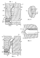
- Figure 1 is a sectional view of a preferred embodiment of the mold apparatus of the present invention, with the mold parts being combined to define the mold cavity for forming a cable tie.
- Figure 2 is a sectional view taken along lines 2-2 in Figure 1 of a portion of the mold cavity, without the cable tie being present therein.
- Figure 3 is a view of that portion of Figure 1 illustrated the juncture of the runner system with the mold cavity, with such portion being enlarged to illustrate the gate by which the runner system communicates with the mold cavity.
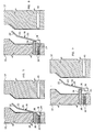
- Figure 4 is a sectional view of the mold apparatus of Figure 1, with the mold parts being separated and the cable tie being partially removed from the mold cavity.
- Figure 5 is a sectional view of the mold apparatus of Figures 1 and 4, with the mold parts being further separated and the tip of cable tie being completely separated from the mold cavity.
- Figure 6 is a sectional view of the mold apparatus of Figures 1, 4 and 5, with the mold parts being further separated and the cable tie being completely ejected from the mold cavity.
- Figure 7 is a sectional view of the mold apparatus of Figures 1, 4, 5 and 6, with the cable tie being ejected from between the mold parts by a forceful fluid stream directed from a closely adjacent nozzle after the cable tie is completely ejected from the mold cavity and separated from the ejector pins.
- a preferred embodiment of the injection molding apparatus of the present invention includes a first mold part 10 and a second mold part 12.
- the first mold part 10 is combined with second mold part 12 to define a mold cavity 14 for forming a cable tie 16.
- the cable tie has a head 18 and a strap 20 terminating in a tip 22 for passing through the head 18.
- the portion of the mold cavity 14 defined by the second mold part 12 defines a series of teeth 23 on one side of the strap 20.
- the first mold part 10 includes a head region 24 defining a major portion of the head 18 of the cable tie; and the second mold part 12 includes a tip region 26 defining a portion of the tip 22 of the cable tie.
- the tip region 26 extends at an angle from a portion 28 of the mold cavity 14 defining most of the strap 20, with said extension being directed away from the bulk of the first mold part 10.
- the tip region 26 includes an undercut region 30 from which the portion of the tip 22 formed therein can be removed only by sliding the tip 22 from the undercut region 30 by pulling the strap 20 of the cable tie 16 from the direction of the head 18.
- the first mold part 10 further includes a pair of protractable ejector pins 32 and a protractable component 34 containing a nozzle 36 and an air passage 38 that communicates with a source of compressed air (not shown).
- the ejector pins 32 are disposed to penetrate the head region 18 from within the first mold part 10, when the ejector pins 32 are protracted.
- the second mold part 12 includes a runner system 40, through which molten plastic material, such as Nylon 6.6, is injected into the mold cavity 14 to form the cable tie 16.
- molten plastic material such as Nylon 6.6
- the runner system 40 is an insulated runner system that communicates with the mold cavity 14 through a gate 42 that converges toward the mold cavity 14 through only the gate 42 and not through a sprue cavity for forming an ejectable sprue, whereby no ejectable sprue is formed.
- the converging gate 42 does not have a hot tip adjacent thereto for applying heat to the plastic being injected into the mold cavity 14.
- a heated tip is unnecessary because of the shortness of the injection cycle achieved in accordance with the method of the present invention.
- Through use of the present invention it has been proven possible to injection mold products in a range of one to five grams at a weight per cycle-time-squared of from 0.1 to 0.5 grams per square second.
- the cable tie 16 separates from the molten plastic at the edge 44 of the mold cavity 14 when the cable tie is separated from the mold cavity 14 to thereby at least substantially reduce the size of any gate spill formed on the cable tie 16.
- the method of the present invention has been successfully practised with a gate opening diameter at the edge 44 of the mold cavity 14 being with a range of between approximately 1.5mm and approximately 2.5mm, and with the angle of convergence between the walls of the gate 42 being within a range of between approximately 15 degrees and approximately 30 degrees.
- a gate opening diameter of 1.8mm and an angle of convergence of 22 degrees are preferred when injecting Nylon 6.6.
- the first mold part 10 is separated from the second mold part 12 while retaining the major portion of the head 18 of the cable tie 16 in the head region 24 of the first mold part and a portion of the tip 22 of the cable tie 16 in the undercut region 30 of the second mold part 12, in order to separate the head 18 of the cable tie from the second mold part 12, to separate the tip 22 from the first mold part 10, and to separate a major portion of the strap 20 of the cable tie 16 from both the first and second mold parts 10,12.
- the major portion of the strap 20 is quickly peeled from the first and second mold parts 10,12 to reduce the ejection portion of the overall cycle time.
- the first mold part 10 is further separated from the second mold part 12 while still retaining the major portion of the head 18 of the cable tie 16 in the head region 24 of the first mold part 10 to thereby remove the tip 22 of the cable tie from the tip region 26 of the second mold part 12 by pulling the strap 20 of the cable tie 16 from the direction of the head 18 to slide the tip 22 from the undercut region 30. It is noted that due to such pulling action, the angle at which the tip 22 of the cable tie 16 extends away from a straight line along most of the length of the strap 20 is less than the angle at which the tip region 26 of the mold cavity defining most of the length of the strip 20.
- the first mold part 10 is further separated from the second mold part 12, and the ejector pins 32 are protracted to eject the head 18 of the cable tie 16 from the head region 24 of the first mold part 10 by pushing on the head 18 with the ejector pins 32.
- the component 34 is also protracted to push on the strap 20 of the cable tie 16 at a position that is closely adjacent the head 18.
- the first mold part 10 is further separated from the second mold part 12, and only the component 34 is further protracted to push the ejected head 18 of the cable tie 16 away from the ejector pins 32 by pushing on the strap 20 of the cable tie at the position that is closely adjacent the head 18.
- the ejector pins 32 are not further protracted.
- a forceful stream of air is then imparted on the head 18 from the closely adjacent nozzle 36 within the protracted component 34 to thereby quickly eject the cable tie 16 from between the first and second mold parts 10,12.
- the stream of air from the nozzle 36 also cools the head 18 of the cable tie so that the cable tie can be ejected at an earlier time in the overall cycle.
- the present invention obviates the need for ejection pins along most of the length of the mold cavity 14, as used in the prior art.
- the present invention preferably is used in multi-cavity injection molding apparatus.
Landscapes
- Engineering & Computer Science (AREA)
- Mechanical Engineering (AREA)
- Manufacturing & Machinery (AREA)
- Physics & Mathematics (AREA)
- Fluid Mechanics (AREA)
- Moulds For Moulding Plastics Or The Like (AREA)
- Injection Moulding Of Plastics Or The Like (AREA)
- Package Frames And Binding Bands (AREA)
- Installation Of Indoor Wiring (AREA)
Claims (6)
- Verfahren zum Spritzgießen eines Kabelbinders 16 mit einem Kopf 18 und einem Band 20, wobei das Verfahren die Schritte aufweist,(a) den Kabelbinder 16 durch Einspritzen von geschmolzenem Kunststoff in einen Formhohlraum 14 auszubilden, der zwischen einem ersten Formteil 10 und einem zweiten Formteil 12 gebildet wird, wobei das erste Formteil einen Kopfbereich 24 aufweist, der einen Abschnitt des Kopfs 18 des Kabelbinders begrenzt,(b) das erste Formteil 10 von dem zweiten Formteil 12 zu trennen, während der Abschnitt des Kopfs 18 des Kabelbinders 16 in dem Kopfbereich 24 des ersten Formteils zurückgehalten wird,(c) den Kopf 18 des Kabelbinders 16 aus dem ersten Formteil 10 auszuwerfen,(d) eine Düse 36, die nahe angrenzend an dem Kopfbereich 24 angeordnet ist, aus dem ersten Formteil 10 auszufahren, und(e) einen Kabelbinder 16 aus dem Raum zwischen dem ersten und zweiten Formteil 10, 12 durch Anlegen eines kräftigen, von der Düse 36 gegen den ausgeworfenen Kopf 18 des Kabelbinders aus gerichteten Fluidstroms auszuwerfen.
- Verfahren nach Anspruch 1, welches weiterhin den Schritt aufweist,
(f) den ausgeworfenen Kopf 18 des Kabelbinders 16 von dem ersten Formteil 10 dadurch wegzudrücken, daß auf das Band 20 des Kabelbinders an einer Stelle, die sich in unmittelbarer Nähe des Kopfes befindet, mit einem die Düse 36 enthaltenden ausgefahrenen Bauteil 34 gedrückt wird. - Verfahren zum Spritzgießen eines Kabelbinders 16 mit einem Kopf 18 und einem Band 20, wobei das Verfahren die Schritte aufweist,(a) den Kabelbinder 16 durch Einspritzen von geschmolzenem Kunststoff in einen Formhohlraum 14 auszubilden, der zwischen einem ersten Formteil 10 und einem zweiten Formteil 12 gebildet wird, wobei das erste Formteil einen Kopfbereich 24 hat, der einen Abschnitt des Kopfs 18 des Kabelbinders begrenzt,(b) das erste Formteil 10 von dem zweiten Formteil 12 zu trennen, während der Abschnitt des Kopfs 18 des Kabelbinders 16 in dem Kopfbereich 24 des ersten Formteils zurückgehalten wird,(c) den Kopf 18 des Kabelbinders aus dem Kopfbereich 24 des ersten Formteils 10 dadurch auszuwerfen, daß auf den Kopf mit wenigstens einem Auswerfer 32 gedrückt wird, der so angeordnet ist, daß er in den Kopfbereich von innerhalb des ersten Formteils aus eindringt und(d) den ausgeworfenen Kopf 18 des Kabelbinders 16 von dem wenigstens einen Auswerfer 32 dadurch wegzudrücken, daß auf das Band 20 des Kabelbinders an einer Stelle in unmittelbarer Nähe des Kopfs mit einem Bauteil 34 gedrückt wird, das von innerhalb des ersten Formteils ausgefahren wird.
- Vorrichtung zum Spritzgießen eines Kabelbinders 16, der einen Kopf 18 und ein Band 20 aufweist,mit einem ersten Formteil 10 und einem zweiten Formteil 12, die, wenn sie zusammengefügt sind, einen Formhohlraum 14 zwischen den Formteilen bilden, um den Kabelbinder 16 auszuformen, wobei das erste Formteil einen Kopfbereich 24 hat, der einen Abschnitt des Kopfs 18 des Kabelbinders begrenzt,mit Einrichtungen 40 zum Einspritzen von geschmolzenem Kunststoff in den Formhohlraum 14 zur Bildung des Kabelbinders 16,wobei das erste Formteil 10 von dem zweiten Formteil 12 trennbar ist, während der Abschnitt des Kopfs 18 des Kabelbinders 16 in dem Kopfbereich 24 des ersten Formteils zurückgehalten wird,mit Einrichtungen 32 zum Auswerfen des Kopfs 18 des Kabelbinders 16 aus dem ersten Formteil 10, nachdem das erste Formteil von dem zweiten Formteil 12 getrennt ist, undmit Einrichtungen zum Auswerfen des Kabelbinders 16 aus dem Raum zwischen dem ersten und zweiten Formteil 10, 12 durch Anlegen eines kräftigen Fluidstroms, der von einer Düse 16 in unmittelbarer Nähe aus gerichtet wird, welche aus dem ersten Formteil ausgefahren ist, gegen den ausgeworfenen Kopf 18 des Kabelbinders.
- Vorrichtung nach Anspruch 4, welche weiterhin Einrichtungen zum Drücken des ausgeworfenen Kopfes 18 des Kabelbinders 16 weg von dem ersten Formteil 10 durch Drücken auf das Band 20 des Kabelbinders an einer Stelle unmittelbar angrenzend an den Kopf mit einem ausgefahrenen Bauteil 34 aufweist, welches die Düse 36 enthält.
- Vorrichtung zum Spritzgießen eines Kabelbinders 16, der einen Kopf 18 und ein Band 20 aufweist,mit einem ersten Formteil 10 und einem zweiten Formteil 12, die, wenn sie zusammengefügt sind, einen Formhohlraum 14 zwischen den Formteilen bilden, um den Kabelbinder 16 auszuformen, wobei das erste Formteil einen Kopfbereich 24 hat, der einen Abschnitt des Kopfs 18 des Kabelbinders begrenzt,mit Einrichtungen 40 zum Einspritzen von geschmolzenem Kunststoff in den Formhohlraum 14 zur Bildung des Kabelbinders 16,wobei das erste Formteil 10 von dem zweiten Formteil 12 trennbar ist, während der Abschnitt des Kopfs 18 des Kabelbinders 16 in dem Kopfbereich 24 des ersten Formteils zurückgehalten ist,mit Einrichtungen zum Auswerfen des Kopfs 18 des Kabelbinders 16 aus dem ersten Formteil 10 durch Drücken auf den Kopf 18 mit wenigstens einem Auswerfer 32, der so angeordnet ist, daß er in den Kopfbereich 24 von innerhalb des ersten Formteils aus eindringt, undmit Einrichtungen zum Drücken des ausgeworfenen Kopfs 18 des Kabelbinders 16 weg von dem wenigstens einen Auswerfer 32 durch Drücken auf das Band 20 des Kabelbinders an einer Stelle in unmittelbarer Nähe des Kopfs mit einem Bauteil 34, das aus dem Inneren des ersten Formteils ausgefahren ist.
Applications Claiming Priority (3)
| Application Number | Priority Date | Filing Date | Title |
|---|---|---|---|
| US07/811,576 US5372773A (en) | 1991-12-20 | 1991-12-20 | Rapid injection molding of elongated articles, such as cable ties |
| US811576 | 1991-12-20 | ||
| EP93901251A EP0618874B1 (de) | 1991-12-20 | 1992-12-16 | Schnelles spritzgiessverfahren für kabelbinder |
Related Parent Applications (2)
| Application Number | Title | Priority Date | Filing Date |
|---|---|---|---|
| EP93901251A Division EP0618874B1 (de) | 1991-12-20 | 1992-12-16 | Schnelles spritzgiessverfahren für kabelbinder |
| EP93901251.4 Division | 1993-07-20 |
Publications (3)
| Publication Number | Publication Date |
|---|---|
| EP0807507A2 EP0807507A2 (de) | 1997-11-19 |
| EP0807507A3 EP0807507A3 (de) | 1999-03-10 |
| EP0807507B1 true EP0807507B1 (de) | 2000-04-26 |
Family
ID=25206937
Family Applications (2)
| Application Number | Title | Priority Date | Filing Date |
|---|---|---|---|
| EP93901251A Expired - Lifetime EP0618874B1 (de) | 1991-12-20 | 1992-12-16 | Schnelles spritzgiessverfahren für kabelbinder |
| EP97113656A Expired - Lifetime EP0807507B1 (de) | 1991-12-20 | 1992-12-16 | Schnelles Spritzgiessen von Kabelbindern |
Family Applications Before (1)
| Application Number | Title | Priority Date | Filing Date |
|---|---|---|---|
| EP93901251A Expired - Lifetime EP0618874B1 (de) | 1991-12-20 | 1992-12-16 | Schnelles spritzgiessverfahren für kabelbinder |
Country Status (5)
| Country | Link |
|---|---|
| US (2) | US5372773A (de) |
| EP (2) | EP0618874B1 (de) |
| JP (1) | JPH07502467A (de) |
| DE (2) | DE69229002T2 (de) |
| WO (1) | WO1993012985A1 (de) |
Families Citing this family (22)
| Publication number | Priority date | Publication date | Assignee | Title |
|---|---|---|---|---|
| US5693282A (en) * | 1995-04-12 | 1997-12-02 | Gb Electrical, Inc. | Removal of injection molded cable tie by imparting gaseous stream to peel strap from mold part |
| US5669111A (en) * | 1995-12-12 | 1997-09-23 | Panduit Corp. | Cable tie having a strengthened neck area |
| US5716582A (en) * | 1996-05-20 | 1998-02-10 | Universal Ventures | Method of and apparatus for ejection of molded product from mold parts |
| US6616884B1 (en) | 2001-03-26 | 2003-09-09 | Soren Christian Sorensen | Removal of cable tie from mold parts |
| US6528004B1 (en) | 2001-05-14 | 2003-03-04 | Soren Christian Sorensen | Removal of portions of cable tie while separating mold parts |
| US6863855B2 (en) | 2001-05-15 | 2005-03-08 | Avery Dennison Corporation | Method of making a cable tie using insert molding |
| WO2003013819A1 (fr) * | 2001-08-07 | 2003-02-20 | Societe De Technologie Michelin | Moule pour bande de roulement de pneumatique |
| US7261853B2 (en) * | 2004-07-16 | 2007-08-28 | Eagle Mold Company | Decelerated ejector pin system and method for operating the same |
| US7544057B1 (en) | 2004-11-09 | 2009-06-09 | Thomas A Wayts | Molding system |
| JP4857852B2 (ja) * | 2005-06-28 | 2012-01-18 | 株式会社デンソー | 成形品の製造方法 |
| US8668860B2 (en) * | 2009-04-02 | 2014-03-11 | Hon Hai Precision Industry Co., Ltd. | Plastic article and method of manufacturing the same |
| CN101856858A (zh) * | 2009-04-08 | 2010-10-13 | 康准电子科技(昆山)有限公司 | 形成具有微结构的模内装饰模制品的方法及其模制品 |
| DE102014012510A1 (de) | 2014-08-23 | 2015-03-12 | Daimler Ag | Befestigungsanordnung und Verfahren zur Herstellung einer Befestigungsanordnung |
| US10279972B2 (en) * | 2017-07-13 | 2019-05-07 | The Boeing Company | Reusable tie |
| CN111867938B (zh) * | 2017-10-30 | 2022-08-05 | 洛克赖特有限责任公司 | 具有弹性体特征的自锁式扎带及其制造方法 |
| KR200485987Y1 (ko) * | 2018-02-12 | 2018-03-20 | 김재로 | 케이블 타이 제작용 금형 장치 및 이에 의하여 제작되는 케이블 타이 |
| GB2578324A (en) * | 2018-10-23 | 2020-05-06 | Rapstrap Ltd | Method of moulding tie strips |
| WO2020131479A1 (en) * | 2018-12-19 | 2020-06-25 | Compagnie Generale Des Etablissements Michelin | Mold with demolding feature for manufacturing a spoke for a non-pneumatic tire |
| DE102019130175A1 (de) * | 2019-11-08 | 2021-05-12 | Hellermanntyton Gmbh | Spritzgussverfahren eines Bauteils, wie beispielsweise eines Kabelhalters, mit einer integrierten Drahtlos-Kennungs-Folie |
| CN114179298B (zh) * | 2021-11-22 | 2024-03-29 | 贾明娥 | 一种连体扎带模具及其使用方法 |
| CN114953392B (zh) * | 2022-05-26 | 2024-02-27 | 上海继尔新材料科技有限公司 | 一种汽车扎带加工挤压成型设备 |
| CN118752712B (zh) * | 2024-08-27 | 2025-02-25 | 高邮市驰越机械有限公司 | 一种具有冷却装置的轮胎生产用橡胶注塑设备 |
Family Cites Families (42)
| Publication number | Priority date | Publication date | Assignee | Title |
|---|---|---|---|---|
| US2929105A (en) * | 1957-04-03 | 1960-03-22 | American Motors Corp | Ejection apparatus for molding machines |
| US3093865A (en) * | 1960-05-16 | 1963-06-18 | Phillips Petroleum Co | Injection molding of plastic materials |
| GB1006373A (en) * | 1961-08-07 | 1965-09-29 | Honda Motor Co Ltd | Improvements in or relating to injection moulding machines |
| DE1145783B (de) * | 1961-08-16 | 1963-03-21 | Ankerwerk Gebr Goller | Vorrichtung zum Auswerfen von Spritzlingen beim Verarbeiten von Kunststoffen auf Spritzgiessmaschinen |
| US3159878A (en) * | 1961-09-14 | 1964-12-08 | Phillips Petroleum Co | Injection molding of plastic materials |
| DE1485656A1 (de) * | 1965-05-04 | 1970-02-12 | Funck Kg Dr Ing | Plattenfoermige Fertig-Laufsohle fuer leichtes,modisches Strassen- oder Luxusschuhwerk |
| US3537676A (en) * | 1967-12-20 | 1970-11-03 | Valve Corp Of America | Mold apparatus for closure with integral cap |
| GB1291880A (en) * | 1969-12-09 | 1972-10-04 | British Insulated Callenders | Improvements in or relating to the manufacture of insulated electric cables |
| DE1800861A1 (de) * | 1968-10-03 | 1970-05-27 | Continental Gummi Werke Ag | Form mit am Formdeckel angeordneten Kernstuecken |
| US4688302A (en) * | 1969-04-07 | 1987-08-25 | Panduit Corp. | One-piece cable tie |
| US3660869A (en) * | 1969-05-01 | 1972-05-09 | Panduit Corp | One-piece cable tie |
| US3965538A (en) * | 1969-05-05 | 1976-06-29 | Panduit Corporation | Integral cable tie |
| US3898315A (en) * | 1971-02-25 | 1975-08-05 | Kent Plastics | Method for removing molds from articles with undercuts |
| US3776676A (en) * | 1972-06-26 | 1973-12-04 | M Kessler | Insulated runner system for plastic cap molds |
| US4005164A (en) * | 1973-01-12 | 1977-01-25 | Hayssen Manufacturing Co. | Method of making plastic containers |
| US4076483A (en) * | 1977-01-24 | 1978-02-28 | Smirne Frank S | Apparatus for ejecting molded article |
| US4192701A (en) * | 1977-07-14 | 1980-03-11 | Brushaber Larry R | Double wall plastic article and method and apparatus for forming a double wall plastic article with a pair of thermoplastic sheets |
| US4238106A (en) * | 1979-12-03 | 1980-12-09 | Owens-Illinois, Inc. | Core pin cooling for high speed injection molding apparatus |
| US4473524A (en) * | 1980-02-28 | 1984-09-25 | Paradis Joseph R | Method for molding and stretching a harnessing device |
| US4354995A (en) * | 1980-09-29 | 1982-10-19 | Western Electric Company, Inc. | Method for making a connector conductor cutter |
| US4427618A (en) * | 1981-01-30 | 1984-01-24 | Sorensen Jens Ole | Inclined insulated runner multicavity injection molding |
| US4666323A (en) * | 1981-06-26 | 1987-05-19 | Milton Kessler | Cap and brush assembly and method of forming it |
| US4432127A (en) * | 1982-03-08 | 1984-02-21 | Mauro Diazzi | Process of molding and assembling a pair of handles of a plastic bag |
| US4562990A (en) * | 1983-06-06 | 1986-01-07 | Rose Robert H | Die venting apparatus in molding of thermoset plastic compounds |
| JPS60196232A (ja) * | 1984-03-15 | 1985-10-04 | Alps Electric Co Ltd | 部品排出装置 |
| DE3526632A1 (de) * | 1985-07-25 | 1987-02-05 | Krauss Maffei Ag | Verfahren und vorrichtung zum herstellen eines spritzgiessteils |
| EP0235997B1 (de) * | 1986-02-17 | 1990-07-18 | SORENSEN, Jens Ole | Kabelbinder |
| US4730615A (en) * | 1986-03-03 | 1988-03-15 | Pfizer Hospital Products Group, Inc. | Sternum closure device |
| US5053179A (en) * | 1987-04-30 | 1991-10-01 | Sumitomo Chemical Company, Limited | Process for producing a multilayer molded article |
| JPH051947Y2 (de) * | 1987-09-04 | 1993-01-19 | ||
| FR2625133B1 (fr) * | 1987-12-24 | 1990-09-21 | Delta Projet | Buse de moule pour injection de matiere plastique |
| GB2214070B (en) * | 1988-01-20 | 1990-11-07 | Ikeda Bussan Co | Covered foamed material for car seats and production thereof |
| US4793793A (en) * | 1988-03-28 | 1988-12-27 | Davidson Textron Inc. | Apparatus having fluid pressure plastic skin folding means for making foamed articles |
| US5028225A (en) * | 1988-07-15 | 1991-07-02 | Staheli Edward O | Apparatus for molding articles to a web |
| GB8907143D0 (en) * | 1989-03-30 | 1989-05-10 | Bowthorpe Hellermann Ltd | Automatic tie gun |
| US5006288A (en) * | 1989-10-12 | 1991-04-09 | Davidson Textron Inc. | Molding method for stabilizing the location of a skin insert |
| US5002480A (en) * | 1989-11-02 | 1991-03-26 | Mold-Masters Limited | Injection molding insulated valve member |
| US5135694A (en) * | 1989-11-10 | 1992-08-04 | Seiko Epson Corporation | Electronic device wristband |
| JP2534800Y2 (ja) * | 1990-04-27 | 1997-05-07 | 大和化成工業 株式会社 | ベルトクランプ |
| US5096651A (en) * | 1990-05-23 | 1992-03-17 | Le Comte Adolf | Method for manufacturing an object of synthetic resin |
| US5146654A (en) * | 1991-05-03 | 1992-09-15 | Panduit Corp. | Stretched cable tie |
| US5123686A (en) * | 1991-09-30 | 1992-06-23 | American Casting & Manufacturing Corporation | Tamper-proof bag seal |
-
1991
- 1991-12-20 US US07/811,576 patent/US5372773A/en not_active Expired - Lifetime
-
1992
- 1992-12-16 EP EP93901251A patent/EP0618874B1/de not_active Expired - Lifetime
- 1992-12-16 JP JP5511739A patent/JPH07502467A/ja active Pending
- 1992-12-16 DE DE69229002T patent/DE69229002T2/de not_active Expired - Fee Related
- 1992-12-16 DE DE69230979T patent/DE69230979T2/de not_active Expired - Fee Related
- 1992-12-16 EP EP97113656A patent/EP0807507B1/de not_active Expired - Lifetime
- 1992-12-16 WO PCT/US1992/010880 patent/WO1993012985A1/en not_active Ceased
-
1994
- 1994-05-31 US US08/251,385 patent/US6217813B1/en not_active Expired - Fee Related
Also Published As
| Publication number | Publication date |
|---|---|
| DE69229002T2 (de) | 1999-08-19 |
| DE69230979T2 (de) | 2000-08-17 |
| EP0807507A2 (de) | 1997-11-19 |
| DE69229002D1 (de) | 1999-05-27 |
| EP0618874A1 (de) | 1994-10-12 |
| JPH07502467A (ja) | 1995-03-16 |
| EP0618874B1 (de) | 1999-04-21 |
| DE69230979D1 (de) | 2000-05-31 |
| EP0807507A3 (de) | 1999-03-10 |
| WO1993012985A1 (en) | 1993-07-08 |
| US6217813B1 (en) | 2001-04-17 |
| US5372773A (en) | 1994-12-13 |
| EP0618874A4 (en) | 1995-08-30 |
Similar Documents
| Publication | Publication Date | Title |
|---|---|---|
| US5372773A (en) | Rapid injection molding of elongated articles, such as cable ties | |
| US5389330A (en) | Injection molding of cable ties | |
| US3660869A (en) | One-piece cable tie | |
| JPS6039538B2 (ja) | 熱可塑性プラスチツクの射出成形方法 | |
| US5440786A (en) | Injection molding of cable ties with a mold having an enhanced core section | |
| US6863855B2 (en) | Method of making a cable tie using insert molding | |
| US6044524A (en) | Removal of injection-molded cable tie from mold | |
| US5693282A (en) | Removal of injection molded cable tie by imparting gaseous stream to peel strap from mold part | |
| US6616884B1 (en) | Removal of cable tie from mold parts | |
| US5435956A (en) | In-mold degating method and apparatus | |
| US5846473A (en) | Removal of injection-molded tie from mold by temporarily retaining core between pawl and abutment surface of tie | |
| US6528004B1 (en) | Removal of portions of cable tie while separating mold parts | |
| US5746965A (en) | Removal of injection-molded tie from mold by retracting core from between pawl and abutment surface of tie | |
| US5716579A (en) | Removal of injection-molded tie from mold by utilizing staggered parting line | |
| US6190599B1 (en) | Removal of injection-molded tie from mold by moving core disposed outside of abutment wall of tie | |
| CA2133524A1 (en) | Method of Forming End Stops Molded on a Slide Fastener Chain and a Chain Splitting Apparatus Used Therein | |
| CA2193301C (en) | Removal of injection-molded tie from mold by utilizing staggered parting line | |
| CA2193300C (en) | Removal of injection-molded tie from mold by temporarily retaining core between pawl and abutment surface of tie | |
| CN215619699U (zh) | 弯钩进浇结构 | |
| GB2308825A (en) | Releasing a tie from an injection mould | |
| JPH09193212A (ja) | 芯材を結束具の爪部と接触面との間から引抜くことにより射出成形結束具を金型から取出す方法 | |
| JPS61163822A (ja) | 射出成形品の取り出し方法 | |
| JPH04201426A (ja) | 射出成形用金型および成形品 | |
| EP0783953A1 (de) | Entfernung eines spritzgegossenen Binders aus einer Form durch temporäres Halten eines Kerns zwischen Klinke und Anschlagfläche des Binders | |
| JPS62288019A (ja) | 射出成形装置 |
Legal Events
| Date | Code | Title | Description |
|---|---|---|---|
| PUAI | Public reference made under article 153(3) epc to a published international application that has entered the european phase |
Free format text: ORIGINAL CODE: 0009012 |
|
| 17P | Request for examination filed |
Effective date: 19970822 |
|
| AC | Divisional application: reference to earlier application |
Ref document number: 618874 Country of ref document: EP |
|
| AK | Designated contracting states |
Kind code of ref document: A2 Designated state(s): DE FR GB IT |
|
| PUAL | Search report despatched |
Free format text: ORIGINAL CODE: 0009013 |
|
| AK | Designated contracting states |
Kind code of ref document: A3 Designated state(s): DE FR GB IT |
|
| GRAG | Despatch of communication of intention to grant |
Free format text: ORIGINAL CODE: EPIDOS AGRA |
|
| 17Q | First examination report despatched |
Effective date: 19990810 |
|
| GRAG | Despatch of communication of intention to grant |
Free format text: ORIGINAL CODE: EPIDOS AGRA |
|
| GRAH | Despatch of communication of intention to grant a patent |
Free format text: ORIGINAL CODE: EPIDOS IGRA |
|
| GRAH | Despatch of communication of intention to grant a patent |
Free format text: ORIGINAL CODE: EPIDOS IGRA |
|
| GRAA | (expected) grant |
Free format text: ORIGINAL CODE: 0009210 |
|
| AC | Divisional application: reference to earlier application |
Ref document number: 618874 Country of ref document: EP |
|
| AK | Designated contracting states |
Kind code of ref document: B1 Designated state(s): DE FR GB IT |
|
| REF | Corresponds to: |
Ref document number: 69230979 Country of ref document: DE Date of ref document: 20000531 |
|
| ET | Fr: translation filed | ||
| ITF | It: translation for a ep patent filed | ||
| PGFP | Annual fee paid to national office [announced via postgrant information from national office to epo] |
Ref country code: GB Payment date: 20001107 Year of fee payment: 9 |
|
| PGFP | Annual fee paid to national office [announced via postgrant information from national office to epo] |
Ref country code: FR Payment date: 20001229 Year of fee payment: 9 |
|
| PLBE | No opposition filed within time limit |
Free format text: ORIGINAL CODE: 0009261 |
|
| STAA | Information on the status of an ep patent application or granted ep patent |
Free format text: STATUS: NO OPPOSITION FILED WITHIN TIME LIMIT |
|
| 26N | No opposition filed | ||
| PG25 | Lapsed in a contracting state [announced via postgrant information from national office to epo] |
Ref country code: DE Free format text: LAPSE BECAUSE OF NON-PAYMENT OF DUE FEES Effective date: 20011002 |
|
| PG25 | Lapsed in a contracting state [announced via postgrant information from national office to epo] |
Ref country code: GB Free format text: LAPSE BECAUSE OF NON-PAYMENT OF DUE FEES Effective date: 20011216 |
|
| REG | Reference to a national code |
Ref country code: GB Ref legal event code: IF02 |
|
| GBPC | Gb: european patent ceased through non-payment of renewal fee |
Effective date: 20011216 |
|
| PG25 | Lapsed in a contracting state [announced via postgrant information from national office to epo] |
Ref country code: FR Free format text: LAPSE BECAUSE OF NON-PAYMENT OF DUE FEES Effective date: 20020830 |
|
| REG | Reference to a national code |
Ref country code: FR Ref legal event code: ST |
|
| PG25 | Lapsed in a contracting state [announced via postgrant information from national office to epo] |
Ref country code: IT Free format text: LAPSE BECAUSE OF NON-PAYMENT OF DUE FEES Effective date: 20051216 |