EP0807504B1 - Doppelzweckauflegewerkzeug - Google Patents
Doppelzweckauflegewerkzeug Download PDFInfo
- Publication number
- EP0807504B1 EP0807504B1 EP97201049A EP97201049A EP0807504B1 EP 0807504 B1 EP0807504 B1 EP 0807504B1 EP 97201049 A EP97201049 A EP 97201049A EP 97201049 A EP97201049 A EP 97201049A EP 0807504 B1 EP0807504 B1 EP 0807504B1
- Authority
- EP
- European Patent Office
- Prior art keywords
- tool
- groove
- machine
- facing surface
- machine tool
- Prior art date
- Legal status (The legal status is an assumption and is not a legal conclusion. Google has not performed a legal analysis and makes no representation as to the accuracy of the status listed.)
- Expired - Lifetime
Links
Images


Classifications
-
- B—PERFORMING OPERATIONS; TRANSPORTING
- B23—MACHINE TOOLS; METAL-WORKING NOT OTHERWISE PROVIDED FOR
- B23Q—DETAILS, COMPONENTS, OR ACCESSORIES FOR MACHINE TOOLS, e.g. ARRANGEMENTS FOR COPYING OR CONTROLLING; MACHINE TOOLS IN GENERAL CHARACTERISED BY THE CONSTRUCTION OF PARTICULAR DETAILS OR COMPONENTS; COMBINATIONS OR ASSOCIATIONS OF METAL-WORKING MACHINES, NOT DIRECTED TO A PARTICULAR RESULT
- B23Q3/00—Devices holding, supporting, or positioning work or tools, of a kind normally removable from the machine
- B23Q3/02—Devices holding, supporting, or positioning work or tools, of a kind normally removable from the machine for mounting on a work-table, tool-slide, or analogous part
- B23Q3/06—Work-clamping means
- B23Q3/08—Work-clamping means other than mechanically-actuated
- B23Q3/086—Work-clamping means other than mechanically-actuated using a solidifying liquid, e.g. with freezing, setting or hardening means
-
- B—PERFORMING OPERATIONS; TRANSPORTING
- B29—WORKING OF PLASTICS; WORKING OF SUBSTANCES IN A PLASTIC STATE IN GENERAL
- B29C—SHAPING OR JOINING OF PLASTICS; SHAPING OF MATERIAL IN A PLASTIC STATE, NOT OTHERWISE PROVIDED FOR; AFTER-TREATMENT OF THE SHAPED PRODUCTS, e.g. REPAIRING
- B29C70/00—Shaping composites, i.e. plastics material comprising reinforcements, fillers or preformed parts, e.g. inserts
- B29C70/04—Shaping composites, i.e. plastics material comprising reinforcements, fillers or preformed parts, e.g. inserts comprising reinforcements only, e.g. self-reinforcing plastics
- B29C70/28—Shaping operations therefor
- B29C70/30—Shaping by lay-up, i.e. applying fibres, tape or broadsheet on a mould, former or core; Shaping by spray-up, i.e. spraying of fibres on a mould, former or core
- B29C70/305—Spray-up of reinforcing fibres with or without matrix to form a non-coherent mat in or on a mould
-
- B—PERFORMING OPERATIONS; TRANSPORTING
- B29—WORKING OF PLASTICS; WORKING OF SUBSTANCES IN A PLASTIC STATE IN GENERAL
- B29C—SHAPING OR JOINING OF PLASTICS; SHAPING OF MATERIAL IN A PLASTIC STATE, NOT OTHERWISE PROVIDED FOR; AFTER-TREATMENT OF THE SHAPED PRODUCTS, e.g. REPAIRING
- B29C70/00—Shaping composites, i.e. plastics material comprising reinforcements, fillers or preformed parts, e.g. inserts
- B29C70/04—Shaping composites, i.e. plastics material comprising reinforcements, fillers or preformed parts, e.g. inserts comprising reinforcements only, e.g. self-reinforcing plastics
- B29C70/28—Shaping operations therefor
- B29C70/54—Component parts, details or accessories; Auxiliary operations, e.g. feeding or storage of prepregs or SMC after impregnation or during ageing
- B29C70/545—Perforating, cutting or machining during or after moulding
-
- Y—GENERAL TAGGING OF NEW TECHNOLOGICAL DEVELOPMENTS; GENERAL TAGGING OF CROSS-SECTIONAL TECHNOLOGIES SPANNING OVER SEVERAL SECTIONS OF THE IPC; TECHNICAL SUBJECTS COVERED BY FORMER USPC CROSS-REFERENCE ART COLLECTIONS [XRACs] AND DIGESTS
- Y10—TECHNICAL SUBJECTS COVERED BY FORMER USPC
- Y10T—TECHNICAL SUBJECTS COVERED BY FORMER US CLASSIFICATION
- Y10T409/00—Gear cutting, milling, or planing
- Y10T409/30—Milling
- Y10T409/303752—Process
- Y10T409/303808—Process including infeeding
-
- Y—GENERAL TAGGING OF NEW TECHNOLOGICAL DEVELOPMENTS; GENERAL TAGGING OF CROSS-SECTIONAL TECHNOLOGIES SPANNING OVER SEVERAL SECTIONS OF THE IPC; TECHNICAL SUBJECTS COVERED BY FORMER USPC CROSS-REFERENCE ART COLLECTIONS [XRACs] AND DIGESTS
- Y10—TECHNICAL SUBJECTS COVERED BY FORMER USPC
- Y10T—TECHNICAL SUBJECTS COVERED BY FORMER US CLASSIFICATION
- Y10T409/00—Gear cutting, milling, or planing
- Y10T409/30—Milling
- Y10T409/304144—Means to trim edge
-
- Y—GENERAL TAGGING OF NEW TECHNOLOGICAL DEVELOPMENTS; GENERAL TAGGING OF CROSS-SECTIONAL TECHNOLOGIES SPANNING OVER SEVERAL SECTIONS OF THE IPC; TECHNICAL SUBJECTS COVERED BY FORMER USPC CROSS-REFERENCE ART COLLECTIONS [XRACs] AND DIGESTS
- Y10—TECHNICAL SUBJECTS COVERED BY FORMER USPC
- Y10T—TECHNICAL SUBJECTS COVERED BY FORMER US CLASSIFICATION
- Y10T409/00—Gear cutting, milling, or planing
- Y10T409/30—Milling
- Y10T409/306664—Milling including means to infeed rotary cutter toward work
- Y10T409/307448—Milling including means to infeed rotary cutter toward work with work holder
-
- Y—GENERAL TAGGING OF NEW TECHNOLOGICAL DEVELOPMENTS; GENERAL TAGGING OF CROSS-SECTIONAL TECHNOLOGIES SPANNING OVER SEVERAL SECTIONS OF THE IPC; TECHNICAL SUBJECTS COVERED BY FORMER USPC CROSS-REFERENCE ART COLLECTIONS [XRACs] AND DIGESTS
- Y10—TECHNICAL SUBJECTS COVERED BY FORMER USPC
- Y10T—TECHNICAL SUBJECTS COVERED BY FORMER US CLASSIFICATION
- Y10T409/00—Gear cutting, milling, or planing
- Y10T409/30—Milling
- Y10T409/30868—Work support
Definitions
- This invention pertains to lay-up tools on which composite parts are made, and more particularly to lay-up tools on which honeycomb core sandwich parts can be laid up, the core bonded to the first face sheet and sculpted, the second face sheet applied and bonded, and the part trimmed, all without removing the part from the tool until it is finished.
- US 5,248,551 discloses a process for producing a reinforced plastic article in accordance with the subject matter of claims 1 and 5 with the exception of the feature of sacrificial material filling the peripheral groove with a top surface flush with the facing surface of the tool body.
- US 4,680,216 discloses a method of stabilizing thick honeycomb core composites.
- honeycomb composite parts have become commonly used throughout industry because of their engineering qualities and low weight.
- honeycomb composite parts having a honeycomb core bonded between two composite face sheets provide excellent strength and stiffness to weight ratios that make them particularly valued and widely used in the aerospace industry.
- they are relatively expensive, in part because the manufacturing processes for producing these parts remain clumsy and difficult to use, contributing high reject and rework rates for composite parts.
- the process for making composite parts includes laying up a tool-side skin, usually several plies of resin-impregnated fiberglass or graphite cloth, on the surface of a tool known as a "bond assembly jig" or BAJ. If the part is to have a honeycomb core, the honeycomb material is cut and fitted onto the tool-side skin and the assembly is covered with a vacuum bag from which the air is withdrawn with a vacuum source. The bagged assembly is inserted into an autoclave and reconnected to the vacuum source while it is heated to cure the resin in the tool-side skin plies and bond the honeycomb to the skin. The bagged assembly is removed from the autoclave and unbagged.
- the part must now undergo a machining operation to shape the honeycomb core to the desired configuration.
- the machining is performed by an CNC machine tool such as a gantry mounted robot, but this machining operation cannot be performed with the part on the BAJ because it has no means for indexing it to a machine bed, and there are no provisions for holding the lay-up assembly on the tool face of the BAJ. More importantly, there is no relief in the tool face into which the cutters can project when edge routing, drilling, or other cutting operations. Instead, the part is broken out of the BAJ, and transferred to another tool known as a "bond mill fixture" or BMF.
- the BMF is designed to have the same profile as the BAJ and is provided with vacuum ports and hold down mechanisms intended to hold the part in place on the BMF while the honeycomb core material is machined to sculpt it to the desired shape.
- the part is removed from the BMF and the honeycomb is cleaned to remove dust from the cells.
- the cleaned part is repositioned onto the BAJ where it is reattached with clamps and hold-down devices.
- the plies that will make up the bag-side skin are laid over the honeycomb core and are recovered with another vacuum bag.
- the BAJ is reinserted back into the autoclave where the bag-side skin is bonded to the honeycomb core. After cure, the cured part is again removed from the BAJ and repositioned onto the BMF for final trim.
- Another object of this invention is to provide an improved process of manufacturing bonded or cured parts from constituent elements in accordance with claim 1, such as face skins or laminates, honeycomb core and resin preimpregnated fabric, that produces parts having greatly improved conformance to dimensional requirements.
- Another object of this invention is to provide a method of manufacturing laid-up bonded and/or cured parts in accordance with claim 5.
- a single tool having a tool body with a facing surface configured to a desired shape of one surface of a part to be made on the tool.
- a groove in the tool body opening in its facing surface is filled with a sacrificial material that forms a top surface flush with the facing surface of the tool body.
- the sacrificial material is a foaming composition that forms a hard smooth skin flush with the facing surface of the tool body.
- Parts are made by laying a tool-side skin or laminate on the tool body and bonding the tool-side skin to the flush surface of the sacrificial material in the peripheral groove.
- Honeycomb core may be placed on the skin and the assembly is bonded and/or cured with the tool-side skin conforming to the surface of the tool.
- the tool After curing, the tool is removed from the autoclave and repositioned on a bed of a CNC machine tool where the honeycomb core is machined to the desired shape using a suitable cutter, and the core is vacuumed to remove the dust.
- the plies for a bag-side skin are applied to the machined surface of the core and the assembly is cured.
- the tool After cure, the tool is accurately relocated on the CNC machine tool bed and a peripheral edge is cut around the part using a cutter on the CNC machine tool.
- the controller of the machine tool is programmed to direct the cutter around the peripheral groove.
- the cutter projects into the peripheral groove and engages the full thickness of the part to cut the peripheral edge.
- edge routing the finished part is removed from the tool.
- the part stays on the tool for the entire manufacturing process, thereby eliminating the usual coordination problems that occur when the part was moved between tools for different manufacturing steps.
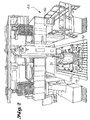
- a dual purpose lay-up tool 30 having a tool body such as a top plate 32 supported by a support structure 34.
- the top plate 32 is made of a material that is compatible with the constituent materials of the part, in terms of chemical and physical properties.
- the top plate 32 preferably should have a coefficient of thermal expansion that matches that of the constituent materials, particularly the layer placed in contact with the top plate (usually referred to as the "tool-side skin").
- the top plate 32 could itself be carbon fiber/epoxy resin composite material, or could be Invar 36, an alloy of nickel and iron having a coefficient of thermal expansion closely matching that of carbon fiber/epoxy resin composite material.
- Aluminum skins with aluminum honeycomb core typically use aluminum tooling which closely match the CTE and are chemically compatible with the aluminum constituent materials.
- the support structure 34 may be any suitable design, although the preferred embodiment is the conventional "egg crate" design shown in Fig. 1. Another support structure which would be suitable would be one made with composite tubes attached together with fittings shown in U.S. Patent No. 5,100,255.
- the support structure 34 has transport accessories to facilitate movement of the tool 30 in the factory.
- the transport accessories in this preferred embodiment include lift rings 36 fastened two each to the front and back sides of the support structure 34 for attachment of lifting cables which are engaged with the hook of an overhead crane for lifting and ferrying the tool 30 about in the factory.
- Another transport accessory which can be used in place of the lift rings 36, or preferably in addition to them, are fork lift tubes 40 built into the support structure 34 as shown in Fig. 1.
- the fork lift tubes 40 receive the spaced tines of a fork lift by which the tool 30 may be lifted and moved about the factory.
- Location and attachment devices are provided on the support structure 34 for accurately indexing and positioning the tool 30 on a base 42 of a machine tool such as a five-axis gantry machine tool 44 shown schematically in Fig. 2, and for fastening the support structure 34 to the machine tool bed 42 in the desired position.
- the machine tool 44 under control by an machine tool controller 46, performs machining operations on the part laid up on the tool 30 after the part is cured.
- the location and attachment devices facilitate precise positioning of the tool 30 on the bed 42 so the machine tool controller can drive the machine tool to the correct position for accurate machining of the part.
- the location devices include set points, sine keys, and tool balls, the use of which are described in detail below.
- the attachment devices by which the tool 30 is secured to the machine tool bed 42 may be any conventional devices known in the art for fastening a workpiece to the bed of a machine tool.
- the attachment devices are conventional toe clamps, the design of which is known to those skilled in the art.
- the top plate 32 has an upper upwardly facing surface 60 on which the constituent elements of the part are laid-up.
- the upper surface 60 is configured to a desired shape of one surface of the part to be made on the tool.
- Upwardly opening recesses are machined into the upper surface 60 of the top plate 32 at positions corresponding to locations on the part that machining operations will be required later in the manufacturing process.
- the recesses include a peripheral groove 62, located on the top plate 32 where the peripheral edge of the part will be cut, and a cylindrical well 63 located on the top plate 32 where holes will be drilled through the part. Other continuous grooves are located within the groove 62 where openings are to be cut out of the part.
- Some of the various shapes of recesses are illustrated in Fig. 6.
- the recesses receive a sacrificial material 64 on which the constituent materials can be laid up on the top plate 32 flush with the upper surface 60.
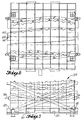
- the groove 62 is preferably dovetailed in cross-section as shown in Fig. 3 which assists in retaining the sacrificial foam material in the groove until it is removed.
- the foam material has a strength of about 500 PSI which is sufficiently strong to provide a supporting surface that holds the tool-side plies flush with the surface of the tool top plate 32 under normal circumstances.
- one or more plies of graphite/epoxy prepreg tape may be added in the groove 62 over the foam material 64 to provide a more rigid surface that is capable, when cured, of distributing the load over a larger surface and thereby carrying a greater load.
- a separate strip of resin-impregnated fabric may be inserted into the groove 62 prior to applying the foam material therein.
- the groove 62 extends completely around the central portion of the facing surface 60 of the top plate 32 on which the constituent elements of the part are to be laid up, in an area of the surface where the net edge trim will be located. Other recesses are located in areas on the tool where holes are to be drilled through the part or where other machining through the part is required.
- the outer peripheral groove is a "continuous" groove in the sense that it completely encircles the area on which the part is laid up. However, there may be particular part designs that require a break or a gap in the groove, hence the term "substantially continuous" groove.
- the groove is just deep enough to enable a mill cutter 68 to extend below the facing surface 60 during its cutting pass so that its peripheral cutting teeth can engage and cut the full thickness of the peripheral edge of the part.
- the depth D of the groove 62 in this embodiment is about 0.050", although it could be made deeper if the machine tool on which the cutter 68 is mounted cannot be programmed to follow the contour of the top plate 32 with the necessary precision.
- the width W of the groove 62 is selected to accommodate the diameter of the cutter 68 plus the necessary tolerance in the path of travel of the cutter 68 in the machine tool 44.
- An additional width of groove 62 is also provided on both sides of the kerf cut by the cutter 68 for holding the tool-side surface of the laid-up materials bonded to the sacrificial material 64 to ensure that the part does not shift during the cutting operation but remains securely fixed in place on the top plate 32 until the cutting operation is completed and the part is ready to be removed from the tool 30.
- the sacrificial material 64 can be any suitable material that can be conveniently applied to fill the groove 62 and has sufficient strength, temperature resistance and other properties to support the constituent materials during the bonding/curing operation.
- the preferred material used in this embodiment is B.F. Goodrich #PL657 heat expandable self-skinning foam. It is applied as a bead or a cut strip in the groove 62 and covered with a smooth molded caul sheet 70, as shown in Fig. 4.
- the caul sheet 70 is preferably a graphite/epoxy resin construction molded directly on the top surface of the top plate 32 before the groove 62 and other recesses are machined therein, and is cured thereon by heating to cure temperature for the cure cycle while covered with an evacuated vacuum bag 71.
- Vacuum tracks 73 may be molded into the underside of the caul sheet 70 by laying a bead of sealing tape, normally used to seal the edges of the vacuum bag 71 to the tool, along both sides of the path on which the groove 62 will be machined in the top plate surface 60.
- the graphite/epoxy sheets of which the caul sheet is made are laid on the tool surface 60 over the beads of tape and cure in that shape to form the vacuum tracks 73.
- the sacrificial material 64 is expanded and cured in the groove by covering the groove 62 with the caul sheet 70 and a vacuum bag, and sealing the edges of the vacuum bag to the facing surface 60 of the top plate 32 with putty-like sealing tape 75 known in the art for this purpose.
- the vacuum bag is evacuated to a vacuum of about 10 inches of vacuum and vacuum is applied in the vacuum tracks 73 to help hold the caul sheet down against the top surface 60 of the tool over the groove 62 while the foam expands against the underside of the caul sheet over the groove 62 and then cures in the expanded condition.
- the tool 30 is place in an oven or autoclave and heated to a temperature specified by the supplier of the foam material, which is about of between 260° for about 90 minutes for the B.F. Goodrich #PL657 material.
- a preferred technique for curing the foam 64 uses an electrically heated caul sheet 72, shown in Fig. 5.
- the caul sheet 72 has an electrical heat tape 74 fastened to the top surface 76 of the caul sheet 72 in the region over the groove 62, or embedded therein when the caul sheet 72 is made.
- An insulating blanket 77 shown partially in phantom lines in Fig. 5, can be laid over the top of the caul sheet 72 to reduce the heat loss to the ambient air and lower the electrical power requirements to maintain an elevated temperature of the foam 64 while it cures.
- Temperature sensors 78 adjacent the heat tape produce signals that are transmitted over conductors 79 to a controller 80 which monitors the temperature of the caul sheet 72 and adjusts the electrical power from a power source 82 delivered to the heat tape 74 to maintain the temperature at the desired cure temperature of the foam 64 in the groove 62.
- the electrically heated caul sheet 72 eliminates the need to occupy an expensive oven during the foam cure cycle, thereby reducing the cost of the manufacturing process.
- the vacuum bag 71 and caul sheet 70 or 72 is removed and a release coating is applied to the tool face 60, on both sides of the groove 62, but is not applied to the sacrificial foam material 64 in the groove 62.
- the release coating ensures that the part will not adhere to the tool face when the time comes to remove it from the tool 30.
- the plies of the tool-side skin 85 of the part are applied to the tool face 60, overlapping the groove 62 and, as shown in Fig. 3, extending a short distance beyond the groove to provide an excess or selvage. If the part is a honeycomb core sandwich part, honeycomb core elements 84 are fit in place on top of the tool-side plies with an adhesive expanding foam between the elements 84. Conveniently, the same expanding foam material 64 used in the groove 62 may be used to bond the honeycomb elements 84 together.
- a breather strip 87 is laid adjacent the tool-side plies 85 and the vacuum bag 71 is laid over the tool-side skin plies 85 and other components, such as the honeycomb core elements 84.
- the peripheral edge of the vacuum bag 71 is sealed to the tool face around the outside of the groove 62 with sealing tape 75 or the like, as known in the art.
- the space under the vacuum bag 71 and inside the periphery of the sealing putty is evacuated by a vacuum pump 86 communicating through a vacuum line 88 with a vacuum port 90 in the tool adjacent the groove 62.
- a check valve (not shown) in the vacuum port holds the vacuum while the tool 30 is transferred into an autoclave (not shown).
- the vacuum port 90 is reconnected to the source 86 of vacuum and the autoclave is pressurized and heated, causing the preimpregnated resin in the plies to flow and then cure while any outgassing from the curing resin is evacuated through the vacuum line 88.
- the temperature and pressure in the autoclave is reduced to RTP and the tool 30 is transported to the machine tool bed 42.
- Retractable feet 94 on the support structure 34 of the tool 30 are retracted to engage a datum surface 96 on the underside of the support structure 34 with the machine tool bed 42. This establishes the vertical position of the facing surface 60 of the tool 30 from the machine bed 42, which is a distance "known" to the machine program that controls the movement of the gantry mounted machine tool 44.
- the retractable feet 94 are kept extended at all other times, that is, during storage and movement of the tool 30 and during lay-up of the skin materials and constituent materials on the tool 30 to protect the accurately ground datum surface 96 from nicks or other damage that could affect the distance between the datum 96 and the top surface 60 of the top plate 32.
- the position and orientation of the tool 30 on the machine bed 42 are established by location devices, including a set point 98 and a sine key 100, shown in Figs. 7 and 8.
- the set point 98 includes a plate 102, fixed rigidly to the underside of the support structure 34 of the tool 30 by welding or the like, and an accurately drilled and lapped vertical hole 104 in the plate 102.
- a precision ground pin 106 typically 2" in diameter, fits with a close sliding fit in the hole 104 and into a selected one of numerous identically sized holes 108 in the machine bed 42, shown in Fig. 2.
- the sine key 100 also shown in Figs. 7 and 8, includes a plate 110 fixed, like the plate 102, to the underside of the support structure 34.
- a smaller vertical hole 112 is accurately drilled and lapped in the plate 110 and receives, also with a close sliding fit, an accurately ground pin 114, typically 13/16" diameter, that extends down beyond the plate 110 and fits into the same T-slot 116 in the machine tool base 42 in which the hole 108 is centered.
- an accurately ground pin 114 typically 13/16" diameter
- the position of the tool 30 is uniquely positioned on the machine tool base 42. Its position can be input to the machine tool control program by identifying the slot 116 and the hole 108 in which the pins are positioned. That information, together with a tool configuration data set and part configuration data set input into the machine tool controller 46, provides sufficient information to enable the machine tool controller to guide the machine tool to perform the required cutting operations.
- FIG. 9 a process is illustrated schematically for transforming digital part data into machine instructions that can be understood and used by the controller of the machine tool 44 to enable it to perform the desired machining operations on the part such as edge routing and hole drilling.
- a digital part model 120 resident on a master computer 122 is provided to an NC machine programmer who produces a program 124 using the part model 120.
- the program contains information such as cutter type, spindle speeds, cutter feed speeds, depth of cut, number of passes and the path to be traversed by the cutter.
- the NC machine program is processed through a post processor 126 to produce a program in a format and medium that can be read by the machine tool controller 46. That program is logged into a data base management system for storage and retrieval when needed.
- the program is retrieved by the machine tool operator when he is ready to make the part. He loads it into the machine tool controller and runs the program to perform the cutting operations on the part after it is properly mounted on the machine tool base 42 and probed to confirm its position.
- Some parts require that separate core assemblies be made apart from the tool-side skin and then be mated in one operation to the tool-side skin and the bag-side skin and co-cured together.
- a single ply of graphite epoxy is laid on the surface 60 of the tool and the elements of honeycomb core are laid atop the tool-side ply.
- Strips of foam material such as the B.F. Goodrich #PL657 material are inserted between the foam core elements.
- a vacuum bag is laid over the assembly and evacuated with a vacuum pump. The tool is put in an autoclave and the temperature and pressure are elevated for the cure cycle.
- the honeycomb core elements lies over the groove and spans the groove, providing support to prevent the vacuum bag from dimpling the foam in the groove 62 before it can cure.
- the tool is taken to the machine tool and mounted on the machine tool bed 42 and indexed in place.
- the core element is machined to produce the sculpted shape desired for the part in which it is to used, and the periphery of the core element is cut following the peripheral groove 62 to free the core element from the tool.
- the sculpted and machined core element is removed and mounted on a tool-side skin in the same or another tool.
- a bag side skin is applied over the core element and a vacuum bag is laid over and sealed to the tool.
- the vacuum bag is evacuated and the tool is put in an autoclave for co-curing both skins simultaneously.
- a vacuum tool 130 shown in Fig. 10 is slip over the top surface of the core element.
- the vacuum tool has a hood 132 having a fitting 134 to which a vacuum hose 136 is attached.
- a pipe 138 is mounted in opposite sides of the hood 132 transverse across its opening.
- the pipe has a row of small holes 140 oriented toward the opening of the hood and has a quick disconnect coupling 142 at its end for attachment to an air pressure hose 144.
- the vacuum tool is connected to a vacuum hose 136 from a source of vacuum, such as a shop vacuum cleaner, and an air hose 144 is connected to the coupling 142.
- the hood is placed with its opening on the surface of the honeycomb core and the air blowing through the row of holes 140 blows the dust out of the honeycomb cells and the vacuum dusty air is withdrawn from the hood 132 through the vacuum hose 136.
- the rate of air blown through the holes 140 is less that the rate of air sucked out of the vacuum hood 132 by the vacuum source, so no dust is blown out of the hood 132.
- a set of shallow notches along the leading edge of the hood 132 allows air to be sucked into the hood and prevents a vacuum condition from building up inside the hood, which could make it difficult to move the hood about over the surface of the core element 84.
- the invention meets the objects noted above by providing a method and apparatus for laying-up and curing/bonding the parts on a lay-up tool, and providing the means for sculpting honeycomb core and trimming and drilling the part while it is still on the original tool and still in the original position. All the registry problems in the prior art process and apparatus are removed by this invention, resulting in substantially improved manufacturing conformance to specified tolerances, and the cost of building, maintaining and storing the tooling is reduced significantly.
- the improved capability of small tolerance manufacturing makes possible, for the first time, use of modern manufacturing techniques with these large laid-up parts, such as statistical tolerancing and determinant assembly, thereby further improving the quality and reducing the cost of the assemblies in which the parts are used.
Landscapes
- Engineering & Computer Science (AREA)
- Mechanical Engineering (AREA)
- Chemical & Material Sciences (AREA)
- Composite Materials (AREA)
- Casting Or Compression Moulding Of Plastics Or The Like (AREA)
- Laminated Bodies (AREA)
- Milling Processes (AREA)
Claims (13)
- Dualzweckwerkzeug (30), das sowohl als eine Form bzw. Schablone dient, auf welcher Komponenten- bzw. Bestandteilsmaterialien zum Binden bzw. Verbinden und/oder Härten zu einem Teil in einer gewünschten Konfiguration an- bzw. aufgebracht werden, als auch zum Halten der genannten Materialien in der ursprünglich an- bzw. aufgebrachten Position während nachfolgender Bearbeitung von einem Umfangsrand des genannten Teils, umfassend:wobei die genannten Materialien für das genannte Teil auf dem Werkzeugkörper (32) an- bzw. aufbringbar, verbindbar bzw. bindbar und/oder härtbar sind, sowie darauf am Rand trimm- bzw. zurichtbar sind, während sie auf dem Werkzeugkörper (32) in der ursprünglich an- bzw. aufgebrachten Position sind.einen Werkzeugkörper (32), der eine Verkleidungs- bzw. Anlageoberfläche (60) hat, die zu einer gewünschten Form von einer Oberfläche von einem Teil konfiguriert ist, das auf dem genannten Werkzeug hergestellt werden soll;eine Träger- bzw. Haltestruktur (34) zum Tragen bzw. Halten des Werkzeugkörpers, um die Verkleidungs- bzw. Anlageoberfläche (60) in der gewünschten Form aufrecht zu erhalten;eine im Wesentlichen kontinuierliche Nut (62) in dem Werkzeugkörper, welche in die Verkleidungs- bzw. Anlageoberfläche (60) mündet;ein Opfermaterial bzw. opferbares Material (64), welches die Nut (62) füllt und eine obere Oberfläche bildet, die mit der Verkleidungs- bzw. Anlageoberfläche des Werkzeugkörpers (32) bündig ist;
- Dualzweckwerkzeug (30), wie im Anspruch 1 definiert, worin:die Nut (32) in der Querschnittsform auf bzw. in einer Ebene, welche senkrecht zu einer Längsachse der Nut (32) ist, schwalbenschwanzförmig ist, wobei die Nut (62) eine Bodenbreite hat, welche weiter als die Breite an der Verkleidungs- bzw. Anlageoberfläche (60) ist.
- Dualzweckwerkzeug (30), wie im Anspruch 1 oder 2 definiert, worin:das Opfermaterial bzw. opferbare Material (64) eine selbst eine Haut bildende schäumende Zusammensetzung ist, welche eine dichte harte Haut bildet, die bündig mit der Verkleidungs- bzw. Anlageoberfläche (60) des Werkzeugkörpers (32) ist, unddas Opfermaterial bzw. opferbare Material (64) darin einen Streifen aus Faser gebunden hat, um die Entfernung des Opfermaterials bzw. opferbaren Material (64) aus der Nut (62) zu erleichtern, nachdem der Umfangsrand um das genannte Teil herum beschnitten bzw. geschliffen bzw. gefräst bzw. spanabhebend bearbeitet worden ist.
- Dualzweckwerkzeug (30), wie im Anspruch 1, 2 oder 3 definiert, weiter umfassend:Lokalisierungseinrichtungen auf bzw. an dem Werkzeug (30) zum genauen Positionieren der Träger- bzw. Haltestruktur (34) und des Werkzeugkörpers (32) auf einem Bett (42) einer Werkzeugmaschine, wobei die Werkzeugmaschine (44) mit Konfigurationsdaten, welche die genannte Nut (32) betreffen, und mit Lokalisierungsdaten, welche die Träger- bzw. Haltestruktur (34) und die Werkzeugkörperposition betreffen, zum automatischen Schneiden bzw. spanabhebenden Bearbeiten des Umfangsrands mittels der Werkzeugmaschine programmiert werden kann, worin:die Lokalisierungseinrichtungen einen Einstell- bzw. Fixpunkt (98) und einen Sinusschlüssel bzw. -bolzen bzw. -keil (100) umfassen, von denen jeder einen genau positionierten Stift bzw. genau positionierte Stifte (106, 114) für das genaue Positionieren der Träger- bzw. Haltestruktur (34) auf dem Werkzeugmaschinenbett (42) hat, und worin:die Lokalisierungseinrichtungen einen Werkzeugkugelsokkel in dem Werkzeugkörper (32) zum Aufnehmen einer Werkzeugkugel umfassen, wobei die Werkzeugkugel eine Oberfläche zum Ineingrifftreten mit einer Sonde hat, welche durch die Werkzeugmaschine betätigt wird, um die aktuelle Position der Bezugsoberflächen auf dem Werkzeug (30) zu lokalisieren.
- Verfahren zum Herstellen von aufgelegten bzw. angehäuften gebundenen und/oder gehärteten Teilen, umfassend:Legen einer werkzeugseitigen Außenlage bzw. Deckschicht auf ein Werkzeug (30), das eine Verkleidungs- bzw. Anlageoberfläche (60) hat, die mit einer gewünschten Formungslinienkonfiguration des genannten Teils konfiguriert ist;Halten bzw. Lagern der werkzeugseitigen Außenlage bzw. Deckschicht auf einem Opfermaterial bzw. opferbaren Material (64), welches eine Umfangsnut um die Außenlage bzw. Deckschicht herum innenbords von einem äußeren Umfangsrand derselben füllt, wobei das Opfermaterial bzw. opferbare Material (64) eine obere Oberfläche hat, die bündig mit der Verkleidungs- bzw. Anlageoberfläche (60) des Werkzeugs (30) ist;Binden der werkzeugseitigen Außenlage bzw. Deckschicht an das Opfermaterial bzw. opferbare Material (64) in der Umfangsnut;Binden und/oder Härten der Außenlage bzw. Deckschicht auf dem Werkzeug (30); undSchneiden bzw. Schleifen bzw. Fräsen bzw. spanabhebendes Bearbeiten eines neuen Umfangsrands auf dem genannten Teil mit einem Schneidwerkzeug bzw. Schleifer bzw. Fräser bzw. spanabhebend bearbeitenden Werkzeug (68) auf einer Maschine folgend der Umfangsnut, wobei sich das Schneidwerkzeug bzw. der Schleifer bzw. der Fräser bzw. das spanabhebend bearbeitende Werkzeug (68) in die Umfangsnut erstreckt, teilweise in das Opfermaterial bzw. opferbare Material schneidet bzw. schleift bzw. fräst bzw. spanabhebend bearbeitet, und mit der vollen Dicke der Außenlage bzw. Deckschicht in Eingriff tritt, um den neuen Umfangsrand zu schneiden bzw. zu schleifen bzw. zu fräsen bzw. durch spanabhebende Bearbeitung zu erzeugen.
- Verfahren des Herstellens von aufgelegten bzw. in Lagen geschichteten gebundenen und/oder gehärteten Teilen, wie im Anspruch 5 definiert, weiter umfassend:Auflegen bzw. in Lagen Schichten von Waben- bzw. Zellenkernmaterialien (84) auf die Oberseite der werkzeugseitigen Außenlage bzw. Deckschicht und Binden der Waben- bzw. Zellenmaterialien (89) an die werkzeugseitige Außenlage bzw. Deckschicht; undBearbeiten der Waben- bzw. Zellenmaterialien (89), um einen Waben- bzw. Zellenkern mit einer geformten bzw. skulpturierten oberen Oberfläche zu erzeugen, die ein Profil hat, welches sich mit einem gewünschten Profil des genannten Teils in Übereinstimmung befindet; undBinden einer beutel- bzw. sackseitigen Haut (85) an die geformte bzw. skulpturierte obere Oberfläche des Waben- bzw. Zellenkerns (84),Blasen von Luft in Zellen des Waben- bzw. Zellenkerns (84) nach dem Bearbeiten, um Staub, welcher während des genannten Bearbeitens des Waben- bzw. Zellenmaterials (89) erzeugt worden ist, mit sich fortzuziehen, undAnwenden von Vakuum- bzw. Unterdrucksog in der Nähe des genannten Blasens, um staubige Luft, die aus den genannten Zellen herausgeblasen wird, zu evakuieren.
- Verfahren des Herstellens eines aufgelegten bzw. in Lagen geschichteten, gebundenen und gehärteten Verbundsteils, wie im Anspruch 5 definiert, umfassend:die Umfangsnut auf bzw. in der Verkleidungs- bzw. Anlageoberfläche des Werkzeugs, die mit dem Opfermaterial bzw. opferbaren Material (64) gefüllt ist, bildet eine Oberfläche darauf, welche bündig mit der Verkleidungs- bzw. Anlageoberfläche ist;Auflegen bzw. Anhäufen der werkzeugseitigen Haut auf der Verkleidungs- bzw. Anlageoberfläche (60) des Werkzeugs (30) und Auflegen bzw. in Lagen Schichten von anderen Komponenten des genannten Teils auf der Oberseite der werkzeugseitigen Haut, wobei die genannte Haut und die Komponenten eine Klebstoff/ Harz-Matrix haben, welche bindet/härtet, um einen starren bzw. steifen integralen Aufbau aus der Haut und den Komponenten zu erzeugen;An- bzw. Aufbringen eines Vakuum- bzw. Unterdruckbeutels bzw. -sacks (71) über die genannte aufgelegte bzw. in Lagen geschichteten Haut und Komponenten und Abdichten von Umfangsbereichen des Vakuum- bzw. Unterdruckbeutels bzw. -sacks (71) um die aufgelegte bzw. in Lagen geschichteten Haut und Komponenten herum;Evakuieren von Luft von unter dem Vakuum- bzw. Unterdruckbeutel bzw. -sack (71), um zu bewirken, dass Luftdruck außenseitig von dem Vakuum- bzw. Unterdruckbeutel bzw. -sack (71) den Vakuum- bzw. Unterdruckbeutel bzw. -sack (71) gegen die genannten Komponenten drückt;Binden/Härten der Klebstoff/Harz-Matrix, um die genannte Haut und die genannten Komponenten in den genannten starren bzw. steifen integralen Aufbau zu transformieren;Entfernen des Vakuum- bzw. Unterdruckbeutels bzw. -sacks (71) von der Verkleidungs- bzw. Anlageoberfläche des Werkzeugs (30), Aufdecken des starren bzw. steifen integralen Aufbaus;Fixieren des Werkzeugs in einer bekannten Position auf einem Bett (42) einer CNC-Werkzeugmaschine unter Verwendung von Lokalisierungseinrichtungen, um die Verkleidungs- bzw. Anlageoberfläche des Werkzeugs (30) in einer bekannten Position für die Randleitung bzw. -dirigierung bzw. -fräsarbeit des starren bzw. steifen integralen Aufbaus durch eine Werkzeugmaschine zu positionieren;Laden eines Datensatzes, der eine digitale Definition des genannten Teils hat, in eine Steuer- bzw. Regeleinrichtung (46) zum Steuern bzw. Regeln des Betriebs der genannten Werkzeugmaschine (30);Führen des Schneidwerkzeugs bzw. Schleifers bzw. Fräsers bzw. spanabhebend bearbeitenden Werkzeugs (68) der Werkzeugmaschine (30), wobei die genannte Steuer- bzw. Regeleinrichtung (46) ein Maschinensteuer- bzw. -regelprogramm, welches den genannten Datensatz enthält, betreibt, auf einem vorbestimmten Weg um die Verkleidungs- bzw. Anlageoberfläche des Werkzeugs (30) herum, wobei das Schneidwerkzeug bzw. der Schleifer bzw. der Fräser bzw. das spanabhebend bearbeitende Werkzeug (68) in das Opfermaterial bzw. opferbare Material (64) in dasselbe unterhalb der Verkleidungs- bzw. Anlageoberfläche des Werkzeugs (30) schneidet bzw. spanabhebend bearbeitet und einen Umfangsrand um den starren bzw. steifen integralen Aufbau herum schneidet bzw. schleift bzw. fräst bzw. durch spanabhebendes Bearbeiten erzeugt;Entfernen des starren bzw. steifen integralen Aufbaus von der Verkleidungs- bzw. Anlageoberfläche des Werkzeugs.
- Verfahren des Herstellens, wie im Anspruch 7 definiert, weiter umfassend:Prüfen des Werkzeugs (30) mit einer Sonde, die auf der CNC-Werkzeugmaschine angebracht ist, um aktuelle Positionen von wenigstens drei Bezugspositionen auf bzw. an dem Werkzeug (30) herzustellen; undNormalisieren bzw. Normieren bzw. Standardisieren des Maschinensteuer- bzw. -regelprogramms mit den genannten aktuellen Positionen der genannten Bezugspunkte, um Daten in dem Maschinensteuer- bzw. -regelprogramm um die genannte Position des Werkzeugs auf dem Maschinenbett herum gegenüber Positionsdaten in der Steuer- bzw. Regeleinrichtung, basierend auf Koordinaten der Lokalisierungseinrichtungen, zu aktualisieren.
- Verfahren des Herstellens, wie im Anspruch 7 oder 8 definiert, worin:der genannten Datensatz in das Maschinenprogramm (124) in der Werkzeugmaschinensteuer- bzw. -regelein-richtung (46) von einem Hauptcomputer (122), in welchem der genannte Datensatz liegt, heruntergeladen wird.
- Verfahren des Herstellens, wie im Anspruch 7 oder 8 definiert, worin:die Nut (62) unter Verwendung der Werkzeugmaschine (30) mit dem genannten Werkzeug auf dem genannten Maschinenbett (42) geschnitten bzw. geschliffen bzw. gefräst bzw. durch spanabhebende Bearbeitung erzeugt wird, um Variationen zwischen unterschiedlichen Werkzeugmaschinen zu minimieren.
- Verfahren des Herstellens, wie in irgendeinem der Ansprüche 7 bis 10 definiert, worin:das Opfermaterial bzw. opferbare Material (64) ein schäumendes, selbst eine Haut bildendes Material ist; undder Schritt des Bildens der Oberfläche des Opfermaterials bzw. opferbaren Materials das Bedecken der Verkleidungs- bzw. Anlageoberfläche des Werkzeugs (30) mit einer Druckkissenplatte bzw. -dünnplatte bzw. -folie (70) umfasst, und das Erhitzen des Werkzeugs (30) und des schäumenden Materials (64) in der Nut (62), um das schäumende Material zu schäumen und zu härten, Füllen der Nut (62) und Bilden einer harten, glatten bzw. gleichmäßigen Oberfläche auf dem Schaum, welche bündig mit der Verkleidungs- bzw. Anlageoberfläche (60) ist.
- Verfahren des Herstellens von Verbundteilen gemäß irgendeinem der vorhergehenden Ansprüche 6-11, umfassend:An- bzw. Aufbringen einer Wulst aus einem schäumenden Material (64) in einer im Wesentlichen kontinuierlichen Nut (62) um einen Auflege- bzw. Lagenschichtungsbereich von einer oberen Oberfläche eines Werkzeugs (30) herum;Legen einer Druckkissenplatte (70) über die Nut (62) und Anwenden von Druck, um die Druckkissenplatte (70) flach gegen die obere Oberfläche des Werkzeugs (30) zu halten;Erhitzen der Druckkissenplatte (70) und dadurch Erhitzen des schäumenden Materials (64) in der Nut (62);Ermöglichen, dass das schäumende Material (64) schäumt und die Nut (62) bis zu der Druckkissenplatte (70) füllt, um eine obere Oberfläche des Schaummaterials zu erzeugen, die bündig mit der oberen Oberfläche des Werkzeugs (30) ist;Ermöglichen, dass das Schaummaterial (64) an Ort und Stelle in der Nut (62) härtet, während der Druck auf der Druckkissenplatte (70) aufrechterhalten wird;Entfernen der Druckkissenplatte (70), nachdem das Schaummaterial (64) gehärtet ist;Auflegen bzw. in Lagen Schichten von Komponentenelementen des genannten Teils und Härten der Elemente an Ort und Stelle auf dem Werkzeug (30), ohne die genannten Elemente von dem Werkzeug (30) zu entfernen;Lokalisieren einer Bezugsoberfläche des Werkzeugs (30) auf dem Bett (42) einer Werkzeugmaschine und Positionieren des Werkzeugs (30) genau auf dem Bett (42) der Werkzeugmaschine so, dass die Position der Nut genau bekannt ist;Programmieren einer Werkzeugmaschinensteuer- bzw. -regeleinrichtung (46) der Werkzeugmaschine (30), um die Werkzeugmaschine (30) dahingehend zu leiten bzw. steuern, dass sie eine Schneideinrichtung bzw. einen Schleifer bzw. einen Fräser bzw. eine spanabhebend bearbeitende Einrichtung (60) um das genannte Teil in der Nut (62) herum antreibt, wobei die Schneideinrichtung bzw. der Schleifer bzw. der Fräser bzw. die spanabhebend bearbeitende Einrichtung (68) mit der vollen Dicke des genannten Teils in Eingriff tritt, um eine genaue Kantentrimmung bzw. -zurichtung des genannten Teils vorzusehen; undEntfernen des Teils von dem Werkzeug (30).
- Verfahren des Herstellens von Verbundteilen, wie im Anspruch 12 definiert, worin:der Schritt des Heizens der Druckkissenplatte (70) während des Härtens des Schaums das elektrische Erregen von elektrischen Heizerelementen in Kontakt mit der Druckkissenplatte (70) umfasst.
Applications Claiming Priority (2)
| Application Number | Priority Date | Filing Date | Title |
|---|---|---|---|
| US08/629,120 US5746553A (en) | 1996-04-08 | 1996-04-08 | Dual purpose lay-up tool |
| US629120 | 1996-04-08 |
Publications (2)
| Publication Number | Publication Date |
|---|---|
| EP0807504A1 EP0807504A1 (de) | 1997-11-19 |
| EP0807504B1 true EP0807504B1 (de) | 2002-10-02 |
Family
ID=24521661
Family Applications (1)
| Application Number | Title | Priority Date | Filing Date |
|---|---|---|---|
| EP97201049A Expired - Lifetime EP0807504B1 (de) | 1996-04-08 | 1997-04-08 | Doppelzweckauflegewerkzeug |
Country Status (6)
| Country | Link |
|---|---|
| US (1) | US5746553A (de) |
| EP (1) | EP0807504B1 (de) |
| KR (1) | KR100469876B1 (de) |
| CN (1) | CN1098152C (de) |
| CA (1) | CA2201981C (de) |
| DE (1) | DE69715959T2 (de) |
Families Citing this family (75)
| Publication number | Priority date | Publication date | Assignee | Title |
|---|---|---|---|---|
| CA2283938C (en) | 1997-05-06 | 2007-04-17 | The Boeing Company | Hybrid lay-up tool |
| US6284089B1 (en) * | 1997-12-23 | 2001-09-04 | The Boeing Company | Thermoplastic seam welds |
| SE519268C2 (sv) * | 1999-12-23 | 2003-02-11 | Saab Ab | Anordning för att hålla en artikel och anläggning för värmebehandling av en artikel |
| US6510601B1 (en) * | 2000-03-20 | 2003-01-28 | The Boeing Company | Invar forming method for making tooling |
| JP4318381B2 (ja) * | 2000-04-27 | 2009-08-19 | 本田技研工業株式会社 | 繊維強化複合材からなる胴体構造体の製造方法、及びそれにより製造される胴体構造体 |
| US6681466B2 (en) | 2001-05-09 | 2004-01-27 | United Air Lines, Inc. | Router replacement method |
| GB0127232D0 (en) * | 2001-11-13 | 2002-01-02 | Bae Systems Plc | A datum system for use in moulding operations |
| US8336596B2 (en) | 2002-11-22 | 2012-12-25 | The Boeing Company | Composite lamination using array of parallel material dispensing heads |
| US7137182B2 (en) * | 2002-11-22 | 2006-11-21 | The Boeing Company | Parallel configuration composite material fabricator |
| US7141191B2 (en) * | 2003-05-02 | 2006-11-28 | The Boeing Company | Triple purpose lay-up tool |
| US7874936B2 (en) * | 2007-12-19 | 2011-01-25 | Taylor Made Golf Company, Inc. | Composite articles and methods for making the same |
| US20080149267A1 (en) * | 2006-12-26 | 2008-06-26 | Taylor Made Golf Company, Inc. | Methods for fabricating composite face plates for use in golf clubs and club-heads for same |
| US7080441B2 (en) * | 2003-07-28 | 2006-07-25 | The Boeing Company | Composite fuselage machine and method of automated composite lay up |
| US7236625B2 (en) * | 2003-07-28 | 2007-06-26 | The Boeing Company | Systems and method for identifying foreign objects and debris (FOD) and defects during fabrication of a composite structure |
| US7138031B2 (en) * | 2003-09-09 | 2006-11-21 | The Boeing Company | Mandrel and method for manufacturing composite structures |
| US7294220B2 (en) * | 2003-10-16 | 2007-11-13 | Toyota Motor Sales, U.S.A., Inc. | Methods of stabilizing and/or sealing core material and stabilized and/or sealed core material |
| US7228611B2 (en) * | 2003-11-18 | 2007-06-12 | The Boeing Company | Method of transferring large uncured composite laminates |
| US7289656B2 (en) * | 2003-12-02 | 2007-10-30 | The Boeing Company | Systems and methods for determining inconsistency characteristics of a composite structure |
| US8934702B2 (en) * | 2003-12-02 | 2015-01-13 | The Boeing Company | System and method for determining cumulative tow gap width |
| US7039485B2 (en) | 2004-03-12 | 2006-05-02 | The Boeing Company | Systems and methods enabling automated return to and/or repair of defects with a material placement machine |
| US7134629B2 (en) * | 2004-04-06 | 2006-11-14 | The Boeing Company | Structural panels for use in aircraft fuselages and other structures |
| US7527222B2 (en) | 2004-04-06 | 2009-05-05 | The Boeing Company | Composite barrel sections for aircraft fuselages and other structures, and methods and systems for manufacturing such barrel sections |
| US7159822B2 (en) * | 2004-04-06 | 2007-01-09 | The Boeing Company | Structural panels for use in aircraft fuselages and other structures |
| US7193696B2 (en) * | 2004-04-12 | 2007-03-20 | United Technologies Corporation | Systems and methods for using light to indicate defect locations on a composite structure |
| US7325771B2 (en) * | 2004-09-23 | 2008-02-05 | The Boeing Company | Splice joints for composite aircraft fuselages and other structures |
| US20060108048A1 (en) | 2004-11-24 | 2006-05-25 | The Boeing Company | In-process vision detection of flaws and fod by back field illumination |
| US7424902B2 (en) * | 2004-11-24 | 2008-09-16 | The Boeing Company | In-process vision detection of flaw and FOD characteristics |
| US7503368B2 (en) * | 2004-11-24 | 2009-03-17 | The Boeing Company | Composite sections for aircraft fuselages and other structures, and methods and systems for manufacturing such sections |
| US20060118244A1 (en) * | 2004-12-02 | 2006-06-08 | The Boeing Company | Device for laying tape materials for aerospace applications |
| US7624488B2 (en) * | 2004-12-07 | 2009-12-01 | The Boeing Company | One-piece barrel assembly cart |
| ES2343643T3 (es) * | 2004-12-30 | 2010-08-05 | Airbus España, S.L. | Procedimiento para la realizacion de embuticiones en zonas planas de piezas de material compuesto preimpregnado. |
| ES2276569B1 (es) * | 2004-12-30 | 2008-06-16 | Airbus España S.L. | Util hibrido para el curado de piezas de material compuesto. |
| US7889907B2 (en) * | 2005-01-12 | 2011-02-15 | The Boeing Company | Apparatus and methods for inspecting tape lamination |
| US7278198B2 (en) * | 2005-02-01 | 2007-10-09 | The Boeing Company | Mandrel segment loader |
| US7748119B2 (en) * | 2005-06-03 | 2010-07-06 | The Boeing Company | Method for manufacturing composite components |
| ES2274701B1 (es) * | 2005-07-15 | 2008-05-01 | GAMESA INNOVATION & TECHNOLOGY, S.L. | Procedimiento de fabricacion de piezas huecas de grandes dimensiones a base de materiales compuestos. |
| US7435947B2 (en) * | 2005-10-31 | 2008-10-14 | The Boeing Company | Apparatus and methods for integrating encoding functions in material placement machines |
| US7372556B2 (en) * | 2005-10-31 | 2008-05-13 | The Boeing Company | Apparatus and methods for inspecting a composite structure for inconsistencies |
| US7398586B2 (en) * | 2005-11-01 | 2008-07-15 | The Boeing Company | Methods and systems for manufacturing a family of aircraft wings and other composite structures |
| DE102006021110B4 (de) * | 2006-05-05 | 2011-04-21 | Airbus Operations Gmbh | Vorrichtung und Verfahren zum Herstellen eines großflächigen Faserverbund-Strukturbauteils |
| DE102006050432B4 (de) * | 2006-08-11 | 2010-10-07 | MV Marketing und Vertriebs-GmbH & Co. KG Wieländer + Schill | Bohrvorrichtung |
| ES2373059T3 (es) * | 2006-10-23 | 2012-01-31 | Constructions Industrielles De La Méditerranée - Cnim | Herramienta de material compuesto para el moldeo de piezas cilíndricas. |
| US9579856B2 (en) | 2007-05-11 | 2017-02-28 | The Boeing Company | Methods and apparatus for molding and joining composite parts |
| US8337654B2 (en) | 2007-05-11 | 2012-12-25 | The Boeing Company | Configurable tooling and molding method using the same |
| US8388795B2 (en) * | 2007-05-17 | 2013-03-05 | The Boeing Company | Nanotube-enhanced interlayers for composite structures |
| US20090035412A1 (en) * | 2007-07-31 | 2009-02-05 | Sobcinski Thomas J | Hybrid lay-up tool |
| US7968021B2 (en) * | 2007-07-31 | 2011-06-28 | The Boeing Company | Coefficient of thermal expansion control structure |
| US8042767B2 (en) | 2007-09-04 | 2011-10-25 | The Boeing Company | Composite fabric with rigid member structure |
| US8196452B2 (en) | 2008-03-27 | 2012-06-12 | The Boeing Company | Collection of process data using in-situ sensors |
| DE102008028076A1 (de) * | 2008-06-13 | 2009-12-17 | Claas Fertigungstechnik Gmbh | Werkzeug, sowie Verfahren zum Herstellen eines Werkzeugs, insbesondere zur Herstellung faserverstärkter Bauteile |
| US8298473B2 (en) * | 2009-05-15 | 2012-10-30 | The Boeing Company | Method of making a cure tool with integrated edge breather |
| US8961732B2 (en) | 2011-01-03 | 2015-02-24 | The Boeing Company | Method and device for compressing a composite radius |
| US8460502B2 (en) | 2011-04-14 | 2013-06-11 | Spirit Aerosystems, Inc. | Method and tooling for manufacture of co-cured composite structures |
| DE102011079928A1 (de) * | 2011-07-27 | 2013-01-31 | Airbus Operations Gmbh | Vorrichtung zur Herstellung eines Klebebauteils mit Faserverbundkunststoffen sowie Verfahren |
| FR2991628A1 (fr) * | 2012-06-12 | 2013-12-13 | Aircelle Sa | Ensemble d'outillage pour la fabrication d'une piece composite et procede de fabrication d'une piece composite. |
| EP2796373B1 (de) * | 2013-04-25 | 2015-12-09 | Airbus Operations GmbH | Anordnungseinspannung zum Montieren von Plattenstrukturelementen auf einer Oberfläche einer CFRP-Platte |
| US9861864B2 (en) | 2013-11-27 | 2018-01-09 | Taylor Made Golf Company, Inc. | Golf club |
| US9511519B2 (en) * | 2014-02-04 | 2016-12-06 | The Boeing Company | System and method of vacuum bagging composite parts |
| US9597843B2 (en) | 2014-05-15 | 2017-03-21 | The Boeing Company | Method and apparatus for layup tooling |
| US9579855B2 (en) * | 2014-12-15 | 2017-02-28 | Spirit Aerosystems, Inc. | Secondary groove for work piece retention during machining |
| US9902091B2 (en) * | 2015-04-21 | 2018-02-27 | Rohr, Inc. | Composite bonding tool with high thermal conductivity and low coefficient of thermal expansion |
| US10513325B2 (en) * | 2016-02-08 | 2019-12-24 | Bell Helicopter Textron Inc. | Joint member for a composite wing structure |
| US10639854B2 (en) | 2016-02-08 | 2020-05-05 | Bell Helicopter Textron Inc. | Composite wing structure and methods of manufacture |
| CN105773991A (zh) * | 2016-03-25 | 2016-07-20 | 哈尔滨飞机工业集团有限责任公司 | 一种小曲率蜂窝结构机翼蒙皮的胶接成型装置及方法 |
| JP2020511334A (ja) * | 2017-03-16 | 2020-04-16 | ザ・ボーイング・カンパニーThe Boeing Company | 第1の熱硬化性複合材と第2の熱硬化性複合材を共接合して硬化複合材部品を構成する方法 |
| US11701801B2 (en) * | 2019-03-04 | 2023-07-18 | The Boeing Company | Caul plate with feature for separating from composite part |
| CN111069697B (zh) * | 2019-12-26 | 2021-04-30 | 济南北方金锋锯业有限公司 | 一种立式锯床 |
| CN111958886B (zh) * | 2020-07-15 | 2022-06-07 | 天津爱思达航天科技有限公司 | 通用式、高成品率的炭泡沫复合材料模具及制备方法 |
| CN112571835B (zh) * | 2020-10-30 | 2022-09-27 | 航天材料及工艺研究所 | 一种适应于自动倾斜铺放的高效示教编程工艺方法 |
| EP4000895A1 (de) | 2020-11-18 | 2022-05-25 | The Boeing Company | Indexiervorrichtung und verfahren zum indexieren |
| JP2022080865A (ja) * | 2020-11-18 | 2022-05-30 | ザ・ボーイング・カンパニー | 複合材部品への指標付けフィーチャの取り付け |
| US12115658B2 (en) * | 2020-11-18 | 2024-10-15 | The Boeing Company | Indexing apparatus and method of indexing |
| NL2027413B1 (en) * | 2021-01-26 | 2022-08-26 | Boeing Co | Indexing apparatus and method of indexing |
| US20240165895A1 (en) * | 2022-11-17 | 2024-05-23 | The Boeing Company | Composite Manufacturing with Reduced Manufacturing Time |
| CN119748884A (zh) * | 2024-12-17 | 2025-04-04 | 哈尔滨飞机工业集团有限责任公司 | 适应固化变形的大长细比复材构件胶接工装及使用方法 |
Family Cites Families (17)
| Publication number | Priority date | Publication date | Assignee | Title |
|---|---|---|---|---|
| US4468160A (en) * | 1982-09-09 | 1984-08-28 | Campbell Automation, Incorporated | Woodworking machine |
| US4795518A (en) * | 1984-02-17 | 1989-01-03 | Burr-Brown Corporation | Method using a multiple device vacuum chuck for an automatic microelectronic bonding apparatus |
| US4680216A (en) * | 1984-09-04 | 1987-07-14 | United Technologies Corporation | Method for stabilizing thick honeycomb core composite articles |
| US4664737A (en) * | 1984-12-13 | 1987-05-12 | The Boeing Company | System for removably attaching blanket to composite material lay-up structure |
| US4786351A (en) * | 1985-12-31 | 1988-11-22 | Astechnologies, Inc. | Process and apparatus for simultaneously shaping foam and laminating fabric thereto |
| US4867829A (en) * | 1987-01-16 | 1989-09-19 | Takashimaya Nippatsu Kogyo Co., Ltd. | Process for producing interior vehicular trim |
| JPH0755467B2 (ja) * | 1987-04-23 | 1995-06-14 | 株式会社川上製作所 | 積層シ−ト材の裁断装置 |
| WO1989008542A1 (fr) * | 1988-03-18 | 1989-09-21 | Takai International Yacht Design Incorporated | Procede de moulage et dispositif de formage d'un article moule stratifie |
| US4913639A (en) * | 1988-09-13 | 1990-04-03 | Wheeler Robert G | Composite caul plate |
| IL88626A0 (en) * | 1988-12-07 | 1989-07-31 | N C T Limited | Method and apparatus for making three-dimensional objects |
| AT396085B (de) * | 1990-07-13 | 1993-05-25 | Gfm Fertigungstechnik | Vorrichtung zum beschneiden raeumlicher formteile aus kunststoff od. dgl. |
| US5145297A (en) * | 1990-11-07 | 1992-09-08 | Northrop Corporation | System and method for particulate matter removal |
| US5248551A (en) * | 1992-04-29 | 1993-09-28 | Davidson Textron Inc. | Bumper preform and method of forming same |
| US5413661A (en) * | 1992-05-13 | 1995-05-09 | R+S Stanztechnik Gmbh | Method for producing a laminated structural component with a hard foam reinforcement |
| US5242523A (en) * | 1992-05-14 | 1993-09-07 | The Boeing Company | Caul and method for bonding and curing intricate composite structures |
| US5411688A (en) * | 1992-06-29 | 1995-05-02 | Duotec Products Associates | Method for forming plastic molded panels with inserts |
| DE29507068U1 (de) * | 1995-04-27 | 1995-09-28 | Paul Kiefel GmbH, 83395 Freilassing | Vorrichtung zum Beschneiden von kaschierten Verkleidungsteilen mit Ultraschall |
-
1996
- 1996-04-08 US US08/629,120 patent/US5746553A/en not_active Expired - Lifetime
-
1997
- 1997-04-07 CA CA002201981A patent/CA2201981C/en not_active Expired - Fee Related
- 1997-04-08 CN CN97110333A patent/CN1098152C/zh not_active Expired - Fee Related
- 1997-04-08 KR KR1019970012788A patent/KR100469876B1/ko not_active Expired - Fee Related
- 1997-04-08 EP EP97201049A patent/EP0807504B1/de not_active Expired - Lifetime
- 1997-04-08 DE DE69715959T patent/DE69715959T2/de not_active Expired - Lifetime
Also Published As
| Publication number | Publication date |
|---|---|
| DE69715959D1 (de) | 2002-11-07 |
| US5746553A (en) | 1998-05-05 |
| CN1168317A (zh) | 1997-12-24 |
| CN1098152C (zh) | 2003-01-08 |
| KR100469876B1 (ko) | 2005-03-16 |
| KR970069310A (ko) | 1997-11-07 |
| CA2201981A1 (en) | 1997-10-08 |
| EP0807504A1 (de) | 1997-11-19 |
| CA2201981C (en) | 2005-11-29 |
| DE69715959T2 (de) | 2003-01-30 |
Similar Documents
| Publication | Publication Date | Title |
|---|---|---|
| EP0807504B1 (de) | Doppelzweckauflegewerkzeug | |
| US6012883A (en) | Hybrid lay-up tool | |
| US7141191B2 (en) | Triple purpose lay-up tool | |
| US11772339B2 (en) | Three-dimensional printing of composite repair patches and structures | |
| EP1231046B1 (de) | Verfahren zur Herstellung von Elementen aus Verbundmaterial durch Co-Bonding Technik | |
| US8568551B2 (en) | Pre-patterned layup kit and method of manufacture | |
| EP1749642B1 (de) | Auflegen von Verbundschichten mit elektronischen Identifikationsetiketten | |
| JP4646919B2 (ja) | 大きな未硬化の複合積層板を移送する方法 | |
| EP2383106B1 (de) | Verfahren und Vorrichtung zur Bildung und Ablage von Verbundlagenwerkstoffen mit komplexen Geometrien | |
| EP2731752B1 (de) | Schnelle herstellung eines verbundteils | |
| EP4163076B1 (de) | Schnelle werkzeugbereitstellung für laminierform und verfahren zum formen eines teils | |
| JP6426414B2 (ja) | 補強付き複合材料パネルの製造 | |
| US20230033757A1 (en) | Method for securing core to tool during machining | |
| EP3862172B1 (de) | Verbundplattewerkzeugsystem und verfahren | |
| WO2007149547A2 (en) | Integrated composite structure | |
| JP2022080865A (ja) | 複合材部品への指標付けフィーチャの取り付け | |
| Burpo et al. | Affordable Integrated Helicopter Fuselage Structure—Full-Scale Article |
Legal Events
| Date | Code | Title | Description |
|---|---|---|---|
| PUAI | Public reference made under article 153(3) epc to a published international application that has entered the european phase |
Free format text: ORIGINAL CODE: 0009012 |
|
| AK | Designated contracting states |
Kind code of ref document: A1 Designated state(s): DE FR GB |
|
| K1C1 | Correction of patent application (title page) published |
Effective date: 19971119 |
|
| 17P | Request for examination filed |
Effective date: 19980129 |
|
| 17Q | First examination report despatched |
Effective date: 19991111 |
|
| GRAG | Despatch of communication of intention to grant |
Free format text: ORIGINAL CODE: EPIDOS AGRA |
|
| GRAG | Despatch of communication of intention to grant |
Free format text: ORIGINAL CODE: EPIDOS AGRA |
|
| GRAH | Despatch of communication of intention to grant a patent |
Free format text: ORIGINAL CODE: EPIDOS IGRA |
|
| GRAH | Despatch of communication of intention to grant a patent |
Free format text: ORIGINAL CODE: EPIDOS IGRA |
|
| GRAA | (expected) grant |
Free format text: ORIGINAL CODE: 0009210 |
|
| AK | Designated contracting states |
Kind code of ref document: B1 Designated state(s): DE FR GB |
|
| REG | Reference to a national code |
Ref country code: GB Ref legal event code: FG4D |
|
| REF | Corresponds to: |
Ref document number: 69715959 Country of ref document: DE Date of ref document: 20021107 |
|
| ET | Fr: translation filed | ||
| PLBE | No opposition filed within time limit |
Free format text: ORIGINAL CODE: 0009261 |
|
| STAA | Information on the status of an ep patent application or granted ep patent |
Free format text: STATUS: NO OPPOSITION FILED WITHIN TIME LIMIT |
|
| 26N | No opposition filed |
Effective date: 20030703 |
|
| REG | Reference to a national code |
Ref country code: GB Ref legal event code: 732E |
|
| REG | Reference to a national code |
Ref country code: FR Ref legal event code: TP |
|
| PGFP | Annual fee paid to national office [announced via postgrant information from national office to epo] |
Ref country code: DE Payment date: 20120419 Year of fee payment: 16 |
|
| PGFP | Annual fee paid to national office [announced via postgrant information from national office to epo] |
Ref country code: FR Payment date: 20120504 Year of fee payment: 16 Ref country code: GB Payment date: 20120404 Year of fee payment: 16 |
|
| GBPC | Gb: european patent ceased through non-payment of renewal fee |
Effective date: 20130408 |
|
| PG25 | Lapsed in a contracting state [announced via postgrant information from national office to epo] |
Ref country code: GB Free format text: LAPSE BECAUSE OF NON-PAYMENT OF DUE FEES Effective date: 20130408 Ref country code: DE Free format text: LAPSE BECAUSE OF NON-PAYMENT OF DUE FEES Effective date: 20131101 |
|
| REG | Reference to a national code |
Ref country code: FR Ref legal event code: ST Effective date: 20131231 |
|
| REG | Reference to a national code |
Ref country code: DE Ref legal event code: R119 Ref document number: 69715959 Country of ref document: DE Effective date: 20131101 |
|
| PG25 | Lapsed in a contracting state [announced via postgrant information from national office to epo] |
Ref country code: FR Free format text: LAPSE BECAUSE OF NON-PAYMENT OF DUE FEES Effective date: 20130430 |