US8042767B2 - Composite fabric with rigid member structure - Google Patents
Composite fabric with rigid member structure Download PDFInfo
- Publication number
- US8042767B2 US8042767B2 US11/849,794 US84979407A US8042767B2 US 8042767 B2 US8042767 B2 US 8042767B2 US 84979407 A US84979407 A US 84979407A US 8042767 B2 US8042767 B2 US 8042767B2
- Authority
- US
- United States
- Prior art keywords
- fabric
- composite structure
- members
- resin
- aircraft fuselage
- Prior art date
- Legal status (The legal status is an assumption and is not a legal conclusion. Google has not performed a legal analysis and makes no representation as to the accuracy of the status listed.)
- Active, expires
Links
- 239000004744 fabric Substances 0.000 title claims abstract description 212
- 239000002131 composite material Substances 0.000 title claims abstract description 37
- 239000011347 resin Substances 0.000 claims abstract description 37
- 229920005989 resin Polymers 0.000 claims abstract description 37
- 239000006260 foam Substances 0.000 claims description 7
- 230000008878 coupling Effects 0.000 claims description 5
- 238000010168 coupling process Methods 0.000 claims description 5
- 238000005859 coupling reaction Methods 0.000 claims description 5
- 238000000034 method Methods 0.000 description 27
- 238000004519 manufacturing process Methods 0.000 description 17
- 238000013461 design Methods 0.000 description 10
- 239000000463 material Substances 0.000 description 9
- 238000010586 diagram Methods 0.000 description 6
- OKTJSMMVPCPJKN-UHFFFAOYSA-N Carbon Chemical compound [C] OKTJSMMVPCPJKN-UHFFFAOYSA-N 0.000 description 4
- 230000008569 process Effects 0.000 description 4
- 229910052799 carbon Inorganic materials 0.000 description 3
- 238000012423 maintenance Methods 0.000 description 3
- 238000012545 processing Methods 0.000 description 3
- 238000000429 assembly Methods 0.000 description 2
- 230000000712 assembly Effects 0.000 description 2
- 238000010276 construction Methods 0.000 description 2
- 238000005516 engineering process Methods 0.000 description 2
- 239000000835 fiber Substances 0.000 description 2
- 229920000049 Carbon (fiber) Polymers 0.000 description 1
- 230000006978 adaptation Effects 0.000 description 1
- 238000013459 approach Methods 0.000 description 1
- 238000005452 bending Methods 0.000 description 1
- 230000015572 biosynthetic process Effects 0.000 description 1
- 239000004917 carbon fiber Substances 0.000 description 1
- 239000007795 chemical reaction product Substances 0.000 description 1
- 239000000356 contaminant Substances 0.000 description 1
- 230000001419 dependent effect Effects 0.000 description 1
- 238000009826 distribution Methods 0.000 description 1
- 230000007613 environmental effect Effects 0.000 description 1
- 238000009408 flooring Methods 0.000 description 1
- 239000011521 glass Substances 0.000 description 1
- 229910002804 graphite Inorganic materials 0.000 description 1
- 239000010439 graphite Substances 0.000 description 1
- 238000002347 injection Methods 0.000 description 1
- 239000007924 injection Substances 0.000 description 1
- 238000007689 inspection Methods 0.000 description 1
- 230000010354 integration Effects 0.000 description 1
- 238000005304 joining Methods 0.000 description 1
- 238000009940 knitting Methods 0.000 description 1
- VNWKTOKETHGBQD-UHFFFAOYSA-N methane Chemical compound C VNWKTOKETHGBQD-UHFFFAOYSA-N 0.000 description 1
- 238000012986 modification Methods 0.000 description 1
- 230000004048 modification Effects 0.000 description 1
- 230000008520 organization Effects 0.000 description 1
- 238000009419 refurbishment Methods 0.000 description 1
- 239000000565 sealant Substances 0.000 description 1
- 238000012549 training Methods 0.000 description 1
- 230000007704 transition Effects 0.000 description 1
Images


Classifications
-
- B—PERFORMING OPERATIONS; TRANSPORTING
- B29—WORKING OF PLASTICS; WORKING OF SUBSTANCES IN A PLASTIC STATE IN GENERAL
- B29C—SHAPING OR JOINING OF PLASTICS; SHAPING OF MATERIAL IN A PLASTIC STATE, NOT OTHERWISE PROVIDED FOR; AFTER-TREATMENT OF THE SHAPED PRODUCTS, e.g. REPAIRING
- B29C70/00—Shaping composites, i.e. plastics material comprising reinforcements, fillers or preformed parts, e.g. inserts
- B29C70/04—Shaping composites, i.e. plastics material comprising reinforcements, fillers or preformed parts, e.g. inserts comprising reinforcements only, e.g. self-reinforcing plastics
- B29C70/28—Shaping operations therefor
- B29C70/40—Shaping or impregnating by compression not applied
- B29C70/42—Shaping or impregnating by compression not applied for producing articles of definite length, i.e. discrete articles
- B29C70/44—Shaping or impregnating by compression not applied for producing articles of definite length, i.e. discrete articles using isostatic pressure, e.g. pressure difference-moulding, vacuum bag-moulding, autoclave-moulding or expanding rubber-moulding
- B29C70/443—Shaping or impregnating by compression not applied for producing articles of definite length, i.e. discrete articles using isostatic pressure, e.g. pressure difference-moulding, vacuum bag-moulding, autoclave-moulding or expanding rubber-moulding and impregnating by vacuum or injection
-
- B—PERFORMING OPERATIONS; TRANSPORTING
- B29—WORKING OF PLASTICS; WORKING OF SUBSTANCES IN A PLASTIC STATE IN GENERAL
- B29C—SHAPING OR JOINING OF PLASTICS; SHAPING OF MATERIAL IN A PLASTIC STATE, NOT OTHERWISE PROVIDED FOR; AFTER-TREATMENT OF THE SHAPED PRODUCTS, e.g. REPAIRING
- B29C70/00—Shaping composites, i.e. plastics material comprising reinforcements, fillers or preformed parts, e.g. inserts
- B29C70/68—Shaping composites, i.e. plastics material comprising reinforcements, fillers or preformed parts, e.g. inserts by incorporating or moulding on preformed parts, e.g. inserts or layers, e.g. foam blocks
- B29C70/86—Incorporated in coherent impregnated reinforcing layers, e.g. by winding
- B29C70/865—Incorporated in coherent impregnated reinforcing layers, e.g. by winding completely encapsulated
-
- B—PERFORMING OPERATIONS; TRANSPORTING
- B64—AIRCRAFT; AVIATION; COSMONAUTICS
- B64C—AEROPLANES; HELICOPTERS
- B64C1/00—Fuselages; Constructional features common to fuselages, wings, stabilising surfaces or the like
- B64C1/06—Frames; Stringers; Longerons ; Fuselage sections
- B64C1/061—Frames
-
- B—PERFORMING OPERATIONS; TRANSPORTING
- B64—AIRCRAFT; AVIATION; COSMONAUTICS
- B64C—AEROPLANES; HELICOPTERS
- B64C1/00—Fuselages; Constructional features common to fuselages, wings, stabilising surfaces or the like
- B64C1/06—Frames; Stringers; Longerons ; Fuselage sections
- B64C1/064—Stringers; Longerons
-
- B—PERFORMING OPERATIONS; TRANSPORTING
- B64—AIRCRAFT; AVIATION; COSMONAUTICS
- B64C—AEROPLANES; HELICOPTERS
- B64C1/00—Fuselages; Constructional features common to fuselages, wings, stabilising surfaces or the like
- B64C1/06—Frames; Stringers; Longerons ; Fuselage sections
- B64C1/12—Construction or attachment of skin panels
-
- B—PERFORMING OPERATIONS; TRANSPORTING
- B29—WORKING OF PLASTICS; WORKING OF SUBSTANCES IN A PLASTIC STATE IN GENERAL
- B29K—INDEXING SCHEME ASSOCIATED WITH SUBCLASSES B29B, B29C OR B29D, RELATING TO MOULDING MATERIALS OR TO MATERIALS FOR MOULDS, REINFORCEMENTS, FILLERS OR PREFORMED PARTS, e.g. INSERTS
- B29K2105/00—Condition, form or state of moulded material or of the material to be shaped
- B29K2105/04—Condition, form or state of moulded material or of the material to be shaped cellular or porous
-
- B—PERFORMING OPERATIONS; TRANSPORTING
- B64—AIRCRAFT; AVIATION; COSMONAUTICS
- B64C—AEROPLANES; HELICOPTERS
- B64C1/00—Fuselages; Constructional features common to fuselages, wings, stabilising surfaces or the like
- B64C2001/0054—Fuselage structures substantially made from particular materials
- B64C2001/0072—Fuselage structures substantially made from particular materials from composite materials
-
- Y—GENERAL TAGGING OF NEW TECHNOLOGICAL DEVELOPMENTS; GENERAL TAGGING OF CROSS-SECTIONAL TECHNOLOGIES SPANNING OVER SEVERAL SECTIONS OF THE IPC; TECHNICAL SUBJECTS COVERED BY FORMER USPC CROSS-REFERENCE ART COLLECTIONS [XRACs] AND DIGESTS
- Y02—TECHNOLOGIES OR APPLICATIONS FOR MITIGATION OR ADAPTATION AGAINST CLIMATE CHANGE
- Y02T—CLIMATE CHANGE MITIGATION TECHNOLOGIES RELATED TO TRANSPORTATION
- Y02T50/00—Aeronautics or air transport
- Y02T50/40—Weight reduction
-
- Y—GENERAL TAGGING OF NEW TECHNOLOGICAL DEVELOPMENTS; GENERAL TAGGING OF CROSS-SECTIONAL TECHNOLOGIES SPANNING OVER SEVERAL SECTIONS OF THE IPC; TECHNICAL SUBJECTS COVERED BY FORMER USPC CROSS-REFERENCE ART COLLECTIONS [XRACs] AND DIGESTS
- Y10—TECHNICAL SUBJECTS COVERED BY FORMER USPC
- Y10T—TECHNICAL SUBJECTS COVERED BY FORMER US CLASSIFICATION
- Y10T156/00—Adhesive bonding and miscellaneous chemical manufacture
- Y10T156/10—Methods of surface bonding and/or assembly therefor
- Y10T156/1002—Methods of surface bonding and/or assembly therefor with permanent bending or reshaping or surface deformation of self sustaining lamina
- Y10T156/1028—Methods of surface bonding and/or assembly therefor with permanent bending or reshaping or surface deformation of self sustaining lamina by bending, drawing or stretch forming sheet to assume shape of configured lamina while in contact therewith
- Y10T156/103—Encasing or enveloping the configured lamina
-
- Y—GENERAL TAGGING OF NEW TECHNOLOGICAL DEVELOPMENTS; GENERAL TAGGING OF CROSS-SECTIONAL TECHNOLOGIES SPANNING OVER SEVERAL SECTIONS OF THE IPC; TECHNICAL SUBJECTS COVERED BY FORMER USPC CROSS-REFERENCE ART COLLECTIONS [XRACs] AND DIGESTS
- Y10—TECHNICAL SUBJECTS COVERED BY FORMER USPC
- Y10T—TECHNICAL SUBJECTS COVERED BY FORMER US CLASSIFICATION
- Y10T156/00—Adhesive bonding and miscellaneous chemical manufacture
- Y10T156/10—Methods of surface bonding and/or assembly therefor
- Y10T156/1002—Methods of surface bonding and/or assembly therefor with permanent bending or reshaping or surface deformation of self sustaining lamina
- Y10T156/1028—Methods of surface bonding and/or assembly therefor with permanent bending or reshaping or surface deformation of self sustaining lamina by bending, drawing or stretch forming sheet to assume shape of configured lamina while in contact therewith
- Y10T156/1033—Flexible sheet to cylinder lamina
-
- Y—GENERAL TAGGING OF NEW TECHNOLOGICAL DEVELOPMENTS; GENERAL TAGGING OF CROSS-SECTIONAL TECHNOLOGIES SPANNING OVER SEVERAL SECTIONS OF THE IPC; TECHNICAL SUBJECTS COVERED BY FORMER USPC CROSS-REFERENCE ART COLLECTIONS [XRACs] AND DIGESTS
- Y10—TECHNICAL SUBJECTS COVERED BY FORMER USPC
- Y10T—TECHNICAL SUBJECTS COVERED BY FORMER US CLASSIFICATION
- Y10T428/00—Stock material or miscellaneous articles
- Y10T428/23—Sheet including cover or casing
- Y10T428/231—Filled with gas other than air; or under vacuum
-
- Y—GENERAL TAGGING OF NEW TECHNOLOGICAL DEVELOPMENTS; GENERAL TAGGING OF CROSS-SECTIONAL TECHNOLOGIES SPANNING OVER SEVERAL SECTIONS OF THE IPC; TECHNICAL SUBJECTS COVERED BY FORMER USPC CROSS-REFERENCE ART COLLECTIONS [XRACs] AND DIGESTS
- Y10—TECHNICAL SUBJECTS COVERED BY FORMER USPC
- Y10T—TECHNICAL SUBJECTS COVERED BY FORMER US CLASSIFICATION
- Y10T428/00—Stock material or miscellaneous articles
- Y10T428/24—Structurally defined web or sheet [e.g., overall dimension, etc.]
- Y10T428/24033—Structurally defined web or sheet [e.g., overall dimension, etc.] including stitching and discrete fastener[s], coating or bond
-
- Y—GENERAL TAGGING OF NEW TECHNOLOGICAL DEVELOPMENTS; GENERAL TAGGING OF CROSS-SECTIONAL TECHNOLOGIES SPANNING OVER SEVERAL SECTIONS OF THE IPC; TECHNICAL SUBJECTS COVERED BY FORMER USPC CROSS-REFERENCE ART COLLECTIONS [XRACs] AND DIGESTS
- Y10—TECHNICAL SUBJECTS COVERED BY FORMER USPC
- Y10T—TECHNICAL SUBJECTS COVERED BY FORMER US CLASSIFICATION
- Y10T428/00—Stock material or miscellaneous articles
- Y10T428/24—Structurally defined web or sheet [e.g., overall dimension, etc.]
- Y10T428/24174—Structurally defined web or sheet [e.g., overall dimension, etc.] including sheet or component perpendicular to plane of web or sheet
-
- Y—GENERAL TAGGING OF NEW TECHNOLOGICAL DEVELOPMENTS; GENERAL TAGGING OF CROSS-SECTIONAL TECHNOLOGIES SPANNING OVER SEVERAL SECTIONS OF THE IPC; TECHNICAL SUBJECTS COVERED BY FORMER USPC CROSS-REFERENCE ART COLLECTIONS [XRACs] AND DIGESTS
- Y10—TECHNICAL SUBJECTS COVERED BY FORMER USPC
- Y10T—TECHNICAL SUBJECTS COVERED BY FORMER US CLASSIFICATION
- Y10T428/00—Stock material or miscellaneous articles
- Y10T428/24—Structurally defined web or sheet [e.g., overall dimension, etc.]
- Y10T428/2419—Fold at edge
-
- Y—GENERAL TAGGING OF NEW TECHNOLOGICAL DEVELOPMENTS; GENERAL TAGGING OF CROSS-SECTIONAL TECHNOLOGIES SPANNING OVER SEVERAL SECTIONS OF THE IPC; TECHNICAL SUBJECTS COVERED BY FORMER USPC CROSS-REFERENCE ART COLLECTIONS [XRACs] AND DIGESTS
- Y10—TECHNICAL SUBJECTS COVERED BY FORMER USPC
- Y10T—TECHNICAL SUBJECTS COVERED BY FORMER US CLASSIFICATION
- Y10T428/00—Stock material or miscellaneous articles
- Y10T428/24—Structurally defined web or sheet [e.g., overall dimension, etc.]
- Y10T428/24628—Nonplanar uniform thickness material
- Y10T428/24636—Embodying mechanically interengaged strand[s], strand-portion[s] or strand-like strip[s] [e.g., weave, knit, etc.]
-
- Y—GENERAL TAGGING OF NEW TECHNOLOGICAL DEVELOPMENTS; GENERAL TAGGING OF CROSS-SECTIONAL TECHNOLOGIES SPANNING OVER SEVERAL SECTIONS OF THE IPC; TECHNICAL SUBJECTS COVERED BY FORMER USPC CROSS-REFERENCE ART COLLECTIONS [XRACs] AND DIGESTS
- Y10—TECHNICAL SUBJECTS COVERED BY FORMER USPC
- Y10T—TECHNICAL SUBJECTS COVERED BY FORMER US CLASSIFICATION
- Y10T428/00—Stock material or miscellaneous articles
- Y10T428/249921—Web or sheet containing structurally defined element or component
Definitions
- Embodiments relate to the field of aircraft construction, and, more specifically, to a composite fuselage section, a system and a method including a composite fabric structure with rigid member.
- the various embodiments may provide a composite structure and a manufacturing process for manufacturing a composite structure, for example, a composite fuselage section.
- the structure and process may use one or more rigid members, such as but not limited to carbon rods, supported by core supports at a distance from the outer mold line fabric lay-up.
- the rigid member may be wrapped with a fabric, the fabric may extend to and may be stitched to the mold line fabric lay-up.
- the rigid member may provide a support structure for the fabric during a cure cycle, and when cured, may form the webbing stringer elements of the structure.
- the rigid member may provide a support element during processing that may eliminate the need for inner mold line tooling which would otherwise be required to maintain the shape of the structure.
- Embodiments may reduce manufacturing costs, and improve part quality as the key structural elements, and may be cured in one operation versus being cured separately and then mechanically fastened together.
- Embodiments may provide a composite structure including: a first fabric; a second fabric; a substantially elongate and substantially rigid first member spaced apart from and coupled with the first fabric via the second fabric; and a resin substantially infused into the first fabric and the second fabric, and substantially encapsulating the first member to form a unitary structure.
- the second fabric may be stitched to the first fabric along one or two seams which may be each substantially parallel with the first member. A portion of the first fabric between the two seams may be disposed to form a loop over the first member to couple the first member with the first fabric.
- a tightening stitch may be disposed through two locations on the second fabric adjacent the first member. A wrapping portion may be defined on the second fabric between the two locations, and the tightening stitch may be adapted to tighten the wrapping portion over the first member.
- a second member may be disposed transverse to the first member and may be coupled with the first fabric via a third fabric.
- the resin may also be substantially infused into the second fabric and may substantially encapsulate the second member.
- the second member and the third fabric may also form part of the unitary structure.
- the unitary structure of the composite structure may form at least part of an aircraft fuselage.
- the first member may be oriented substantially parallel with a longitudinal axis of the fuselage, and the first fabric with the infused resin may be adapted to form a skin of the aircraft fuselage.
- the second member may form at least part of a cross-sectional frame member of the aircraft fuselage.
- the composite structure of various embodiments may include a first member disposed to pass through the second member.
- the first member may be a pultruded rod.
- At least part of the second member may be made from foam core.
- the second fabric may be a warp-knit fabric and the warp of the fabric may be oriented substantially perpendicular to a longitudinal axis of the elongate first member.
- Embodiments may include a method of manufacturing a composite structure.
- the method may include:
- the covering the first member with the second fabric may include positioning the second fabric in a slot of a fixture forming a valley with the second fabric and positioning the rod in the valley.
- the forming a unitary structure includes infusing the resin into the third fabric and encasing the second member within the resin.
- the securing the second fabric and the securing the third fabric may be by stitching.
- the method may also include curing the resin.
- the first member may be a pultruded rod.
- the second fabric may be a warp-knit fabric and may further comprise orienting the warp of the warp-knit substantially perpendicular to a longitudinal axis of the elongate first member.
- Embodiments may provide an aircraft fuselage including: a fuselage skin including a first fabric; two or more stringer members oriented longitudinally within the fuselage each including an elongate rigid first member disposed a distance from the skin and coupled with the skin via a second fabric, two or more frame members of sufficient rigidity to support the first members at the distance from the skin and coupled with the skin via a third fabric; and a resin infused into the first, second, and third fabrics and which substantially encapsulates the first and second members.
- Embodiments providing an aircraft fuselage may include the second fabric being looped over the first member.
- the second fabric may be long enough to form at least one tab-like portion that contacts the first fabric.
- the at least one tab-like portion may be stitched to the first fabric.
- the first members may be pultruded rods. At least part of the two or more of the frame members may be made from foam core.
- the second fabric may be a warp-knit fabric and the warp of the fabric may be oriented substantially perpendicular to longitudinal axes of the elongate rigid first members.
- Various embodiments may provide an assembly to form a composite assembly, which may include: a first fabric laid on a surface; a second member laid on the first fabric; a third fabric draped over the second member, having two flaps that extend beyond either side of the second member.
- the two flaps may each be stitched to the first fabric.
- An elongate first member may pass through the second member and may be supported by the second member a distance from the first fabric.
- a second fabric may be draped over the first member which may have two other flaps that extend down from the first member.
- the two other flaps may each be stitched to the first fabric.
- the assembly may also include a substantially airtight film placed over the first and second members and the first, second, and third fabrics.
- the assembly may also be adapted to form a vacuum seal between the film and the surface, and further adapted for a resin to be introduced between the film and the surface.
- the first and second members may be included in at least a portion of the completed composite assembly.
- FIG. 1 is a flow diagram of aircraft production and service methodology
- FIG. 2 is a block diagram of an aircraft
- FIG. 3A illustrates a perspective view
- FIG. 3B an exploded perspective view in accordance with various embodiments
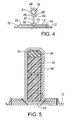
- FIG. 4 illustrates a cross-sectional view taken at line 4 - 4 in FIG. 3A ;
- FIG. 5 illustrates a cross-sectional view a portion of a flooring panel taken at line 5 - 5 in FIG. 3A ;
- FIG. 6 illustrates an end view of a fixture that may be used in the assembly of various embodiments
- FIG. 7 illustrates a side view with portions in cutaway view for illustration in accordance with various embodiments
- FIG. 8 illustrates a somewhat schematic view of portions of an assembly process in accordance with various embodiments
- FIGS. 9A and 9B illustrate cross-sectional views of respectively different embodiments illustrating selected design parameters being varied and respective varied resultant structures
- FIG. 10A illustrates a side view and FIG. 10B illustrates a cross-sectional view taken at the line 10 B- 10 B in accordance with various embodiments;
- FIG. 11A is a block diagram and FIG. 11B is a cross-sectional view taken at the line 11 B- 11 B in FIG. 11A ;
- FIG. 12 is a flow diagram illustrating a method in accordance with various embodiments.
- FIG. 13 is a flow diagram illustrating a method in accordance with various embodiments.
- Coupled may mean that two or more elements are in direct physical or electrical contact. However, “coupled” may also mean that two or more elements are not in direct contact with each other, but yet still cooperate or interact with each other.
- a phrase in the form “A/B” means A or B.
- a phrase in the form “A and/or B” means “(A), (B), or (A and B).”
- a phrase in the form “at least one of A, B, and C” means “(A), (B), (C), (A and B), (A and C), (B and C), or (A, B and C).”
- a phrase in the form “(A)B” means “(B) or (AB),” that is, A is an optional element.
- Embodiments may provide a very efficient airframe structure having the skin, stringers, and frame elements which may maintain residual load-carrying capabilities under a variety of damage scenarios. Embodiments may enable higher operating strains and ultimately a lighter airframe.
- embodiments of, for example, dry carbon fiber, pultruded rods, and stitching thread may also provide manufacturing advantages.
- a self-supporting stitched preform design of various embodiments may include a new out-of-autoclave fabrication approach that may provide orders of magnitude lower building costs than would otherwise be possible using traditional composite design and manufacturing practices.
- Embodiments may provide larger one-piece occurred panel designs with seamless transitions and damage-arrest interfaces. Embodiments may also provide performance and cost advantages that are capable of enabling a whole new generation of highly-contoured aircraft designs that may result in substantially improved mission capabilities and lower life cycle costs for future aircraft, including military aircraft.
- exemplary method 100 may include specification and design 104 of the aircraft 102 and material procurement 106 .
- component and subassembly manufacturing 108 and system integration 110 of the aircraft 102 takes place.
- the aircraft 102 may go through certification and delivery 112 in order to be placed in service 114 .
- routine maintenance and service 116 which may also include modification, reconfiguration, refurbishment, and so on).
- a system integrator may include without limitation any number of aircraft manufacturers and major-system subcontractors; a third party may include without limitation any number of venders, subcontractors, and suppliers; and an operator may be an airline, leasing company, military entity, service organization, and so on.
- the aircraft 102 produced by exemplary method 100 may include an airframe 118 with a plurality of systems 120 and an interior 122 .
- high-level systems 120 include one or more of a propulsion system 124 , an electrical system 126 , a hydraulic system 128 , and an environmental system 130 . Any number of other systems may be included.
- an aerospace example is shown, the principles of the invention may be applied to other industries, such as the automotive industry.
- Apparatus and methods embodied herein may be employed during any one or more of the stages of the production and service method 100 .
- components or subassemblies corresponding to production process 108 may be fabricated or manufactured in a manner similar to components or subassemblies produced while the aircraft 102 is in service.
- one or more apparatus embodiments, method embodiments, or a combination thereof may be utilized during the production stages 108 and 110 , for example, by substantially expediting assembly of or reducing the cost of an aircraft 102 .
- one or more of apparatus embodiments, method embodiments, or a combination thereof may be utilized while the aircraft 102 is in service, for example and without limitation, to maintenance and service 116 .
- FIG. 3A is a perspective view and FIG. 3B is an exploded perspective view illustrating various embodiments.
- a composite structure 10 may include a first fabric 12 , and a second fabric 14 .
- the embodiment illustrated may include a substantially elongate and substantially rigid first member 16 spaced apart from and coupled with the first fabric 12 via the second fabric 14 .
- the first member 16 may be spaced from the first fabric 12 by a distance 18 .
- a resin may be infused into the first fabric 12 and the second fabric 14 , and may also encapsulate the first member 16 to form a unitary structure 11 . Examples of structure and methods for applying the resin in accordance with various embodiments are discussed below.
- FIG. 4 is a cross-sectional view taken through the line 4 - 4 in FIG. 3A .
- the second fabric 14 may be stitched to the first fabric 12 along two seams 20 .
- Each of the seams 20 may be substantially parallel with the first member 16 such that a portion 22 of the first fabric between the two seams 20 may be disposed to form a loop 21 over the first member 16 to couple the first member 16 with the first fabric 12 .
- first member 16 is shown as a rod for illustration and without limitation any structural shape may be used. While first member 16 is shown with a uniform cross section over its length, the cross section shape and/or size of first member 16 may vary over its length.
- a tightening stitch 24 may be disposed through two locations 26 on the second fabric 14 adjacent the first member 16 .
- a wrapping portion 28 may be defined on the second fabric 14 between the two locations 26 .
- the tightening stitch 24 may be adapted to tighten the wrapping portion 28 over the first member 16 .
- Additional stitching rows 30 may also serve to couple the second fabric 14 to the first fabric 12 .
- a tear strap 32 may be disposed between the first fabric 12 and the second fabric 14 .
- FIG. 5 is a cross-sectional view taken through the line 5 - 5 in FIG. 3A .
- a second member 34 may be disposed transverse to the first member 16 and may be coupled with the first fabric 12 via a third fabric 36 .
- the resin may also be infused into the third fabric 36 and may encapsulate the second member 34 .
- the second member 34 and the third fabric 36 may form part of the unitary structure 11 .
- First and second members could be graphite and/or foam or some other material. Both could be any structural shape and/or have a cross section that varies over its length.
- the first member 16 may pass through the second member 34 .
- the second member 34 may support the first member 16 at the distance 18 ( FIG. 3A ).
- the first member 16 may be a pultruded rod. At least part of the second member 34 may be made substantially from foam core.
- the fuselage may include a fuselage skin 12 ′.
- the fuselage skin 12 ′ may include a first fabric 12 .
- Two or more stringer members 15 may be oriented longitudinally with a longitudinal axis 40 of the fuselage.
- Each stringer members 15 may include an elongate rigid first member 16 disposed a distance 18 from the fuselage skin 12 ′.
- Each elongate rigid and first member 16 may be coupled with the fuselage skin 12 ′ via a second fabric 14 .
- Two or more frame members 34 ′ may be oriented transverse to the fuselage and may be of sufficient rigidity to provide support for the first members 16 at the distance 18 from the skin 12 ′.
- the frame members 34 ′ may be coupled with the skin 12 ′ via a third fabric 36 .
- a resin may be infused into the first 12 , second 14 , and third fabrics 36 and may encapsulate the first 16 and second members 34 .
- the second fabric 14 may be looped over the first member 16 and may be long enough to form at least one tab-like portion 70 that contacts the first fabric 12 .
- the at least one tab-like portion 70 may be stitched to the first fabric 12 .
- Frame members 34 ′ may run perpendicular to the stringers 16 ′ in a radial direction 41 and may be spaced at, for example, roughly 20-inch intervals and may be constructed, for example and without limitation, from a foam-core design wrapped within warp-knit fabric.
- the second members 34 may include additional material buildups at the top 31 and base 33 to provide bending stiffness.
- frame caps 35 (FIG. 5 ) may be used and may be continuous annularly around the fuselage.
- Slots 37 FIG. 3B ) may be cut in frame member 34 ′ webs 43 to allow stringer members 15 ′ to pass through. The excess frame web material at each stringer slot 37 may drape around the stringer members 15 ′ to provide a fillet flange that would strengthen the intersection.
- Other prominent airframe features like window and door assemblies may also be included in an integrated design.
- FIG. 5 illustrates the third fabric 36 as having two plies or layers of fabric.
- Various embodiments may use various numbers of layers, various fabric types and technologies for any and all of the first, second, and third fabrics.
- a dry warp-knit fabric may be used.
- Warp-knitting technology may provide the flexibility of mixing tow concentrations and material types.
- carbon and glass of various tensile strengths and moduli, at various orientations and locations may be utilized to create highly optimized multiaxial fabrics. These fabrics can be specifically tailored for different applications and in the case of aircraft fuselage construction for different aircraft types and loading conditions to optimize cost and weight.
- Embodiments may enable a multirole design because it may offer an inexpensive way to optimize the weight and cost performance of the basic material for each application or aircraft type.
- multiple aircraft differing roles i.e., bomber, passenger, etc. may be assembled using common tooling and common parts but having differing features.
- FIG. 6 is an end view illustrating various embodiments wherein a fixture 50 may be used as an aide to assemble various elements.
- Multiple, for example six, second fabrics 14 may be positioned in multiple slots 52 in the fixture 50 forming multiple valleys, or pockets 54 with the second fabrics 14 .
- Multiple first members 16 in the form of elongated rods 16 may be positioned in the valleys, or pockets 54 .
- One or more second member 34 may be disposed in respective one or more transverse slots 53 in the fixture 50 .
- the one or more second members may include slots 37 through which the first members 16 and second fabrics may pass.
- the slots may be keyhole shaped as illustrated, and may be adopted to support the first members 16 during fabrication.
- the first fabric 12 may then be coupled with each of the second fabrics 14 .
- FIG. 7 is a side view with a portion cutaway for illustration of an assembly in accordance with various embodiments.
- the assembly illustrated in FIG. 4 may be removed from the fixture and placed on a surface 56 which may be on an outer mold line 58 .
- a substantially airtight film 60 may be placed over the first and second members 16 , 34 and the first, second and third fabrics 12 , 14 , 36 , and adapted to form a vacuum seal between the film 60 and the surface 56 .
- the first and second members 16 , 34 may be included in at least a portion of the completed composite assembly.
- FIG. 8 is a cross-sectional view illustrating, somewhat schematically, embodiments wherein the resin may be introduced and/or infused into the assembly.
- the resin may be pushed through the assembly which may be a dry carbon perform by a vacuum-induced pressure differential, that may not only promote resin flow but which may also create a pressure differential across the film 60 vacuum bag surface.
- a resin inlet 62 may introduce the resin under the film 60 while, or after, or just before a vacuum line 64 creates the pressure differential. This pressure may compact the preform and may enable laminate fiber volumes of nearly 60%. Even relatively low-pressure processing techniques may achieve higher fiber volume fractions and mechanical properties. The process may be superior to state-of-the-art prepreg material systems that typically require autoclave processing environments.
- the edges 66 of the film 60 may be sealed to a surface 56 of a mold 58 with a seal 68 , such as a sealant tape. As illustrated the seal 68 may pass over, for example, the vacuum line 64 .
- a peel ply 70 may be used to, without limitation, leave a clean and contaminant free surface, and/or leave a textured surface. The peel ply 70 may be applied as the last material in the composite laminate sequence, and may be removed following a curing operation.
- a breather or bleeder fabric 72 may be used to, for example, to ensure that air or other gas sealed under the vacuum bag can be easily extracted and for more uniform vacuum distribution. The breather fabric 72 may also absorb excess resin that may be bled from the laminate.
- FIGS. 9A and 9B illustrate cross-sectional views similar to FIG. 4 in accordance with various embodiments.
- Each view illustrates a first member 16 disposed at a distance 18 or 18 ′ from the first fabric 12 , and coupled to the first fabric 12 with the second fabric 14 .
- Each arrangement is illustrated between a substantially air tight film 60 and an outer mold line 58 surface 56 .
- a comparison of FIGS. 9A and 9B may illustrate the versatility of various embodiments, as the same outer mold line 58 may be used for various end products by simply varying selected parameters of the design with little or no additional investment in tooling or training.
- FIG. 10A is a front view and FIG. 10B is a side view taken through the line 10 B- 10 B of FIG. 10A in accordance with various embodiments.
- a substantially elongate and substantially rigid first member 216 may be coupled with the first fabric 212 via a second fabric 214 , and spaced a first distance 218 from the first fabric 212 .
- a substantially elongate and substantially rigid second member 316 may be coupled with the first fabric 212 via a third fabric 314 , and spaced a second distance 318 from the first fabric 212 .
- a substantially rigid insert 334 may be disposed within the third fabric 314 .
- the insert 334 may be adopted to support the first member 216 , and may also be adopted to support and/or maintain the second member 316 at the distance 318 .
- the insert 334 may be foam core 334 .
- the third fabric 314 may include a hole 380 located to enable something to pass through, for example and without limitation, a pipe, wiring or conduit.
- the hole 380 may also be adapted as a window, or an opening for inspection and/or maintenance.
- a resin may be infused into the first fabric 212 , the second fabric 214 and third fabric 314 , and may also encapsulate the first member 216 and the second member 316 , to form a unitary structure 211 .
- FIG. 11A is a block diagram and FIG. 11B is a cross-sectional view taken at the line 11 B- 11 B in FIG. 11A illustrating various embodiments.
- a composite structure 1010 may include a first fabric 1012 , a second fabric 1014 , and a substantially elongate and substantially rigid first member 1016 spaced apart from and coupled with the first fabric 1012 via the second fabric 1014 .
- the composite structure 1010 may further include a second member 1034 disposed transverse to the first member 1016 and coupled with the first fabric 1012 via a third fabric 1036 .
- FIG. 12 illustrates a method 400 in accordance with various embodiments.
- the method may include a method of manufacturing a composite structure comprising: laying out a first fabric on a tool surface, 402 ;
- first member covering the first member with a second fabric such that tab-like portions of the second fabric contact the first fabric on opposite sides of the first member, 406 ;
- the covering the first member with the second fabric may include positioning the second fabric in a slot of a fixture forming a valley with the second fabric and positioning the rod in the valley.
- any or all of the first member, second member, and first and second fabrics may be tacked together using a tackifier. This may allow formation of more complex preforms in the steps prior to debalking, resin injection, and curing. Tacking together may be used along with, or instead of, stitching.
- a method 500 shown in FIG. 13 , may further comprise:
- the infusing includes introducing the resin between the tool surface and the film, 504 .
- Various embodiments may use operations that may be the same as or substantially similar to operations in methods described herein, or may be included with devices the same, or similar to, those described herein, that may utilize a pre-impregnated material already impregnated with a resin, also known as “prepreg”.
Landscapes
- Engineering & Computer Science (AREA)
- Mechanical Engineering (AREA)
- Aviation & Aerospace Engineering (AREA)
- Chemical & Material Sciences (AREA)
- Composite Materials (AREA)
- Moulding By Coating Moulds (AREA)
- Casting Or Compression Moulding Of Plastics Or The Like (AREA)
Abstract
Description
Claims (21)
Priority Applications (2)
| Application Number | Priority Date | Filing Date | Title |
|---|---|---|---|
| US11/849,794 US8042767B2 (en) | 2007-09-04 | 2007-09-04 | Composite fabric with rigid member structure |
| US13/194,698 US8728263B2 (en) | 2007-09-04 | 2011-07-29 | Composite fabric with rigid member structure |
Applications Claiming Priority (1)
| Application Number | Priority Date | Filing Date | Title |
|---|---|---|---|
| US11/849,794 US8042767B2 (en) | 2007-09-04 | 2007-09-04 | Composite fabric with rigid member structure |
Related Child Applications (1)
| Application Number | Title | Priority Date | Filing Date |
|---|---|---|---|
| US13/194,698 Division US8728263B2 (en) | 2007-09-04 | 2011-07-29 | Composite fabric with rigid member structure |
Publications (2)
| Publication Number | Publication Date |
|---|---|
| US20090057487A1 US20090057487A1 (en) | 2009-03-05 |
| US8042767B2 true US8042767B2 (en) | 2011-10-25 |
Family
ID=40405872
Family Applications (2)
| Application Number | Title | Priority Date | Filing Date |
|---|---|---|---|
| US11/849,794 Active 2030-08-23 US8042767B2 (en) | 2007-09-04 | 2007-09-04 | Composite fabric with rigid member structure |
| US13/194,698 Active 2027-12-02 US8728263B2 (en) | 2007-09-04 | 2011-07-29 | Composite fabric with rigid member structure |
Family Applications After (1)
| Application Number | Title | Priority Date | Filing Date |
|---|---|---|---|
| US13/194,698 Active 2027-12-02 US8728263B2 (en) | 2007-09-04 | 2011-07-29 | Composite fabric with rigid member structure |
Country Status (1)
| Country | Link |
|---|---|
| US (2) | US8042767B2 (en) |
Cited By (31)
| Publication number | Priority date | Publication date | Assignee | Title |
|---|---|---|---|---|
| US20090283638A1 (en) * | 2008-05-16 | 2009-11-19 | Airbus Espana S.L. | Integrated aircraft structure in composite material |
| US20100012787A1 (en) * | 2008-07-18 | 2010-01-21 | Michael Leslie Hand | Strong bonded joints for cryogenic application |
| US20100043305A1 (en) * | 2005-08-19 | 2010-02-25 | Nuala Donnellan | Composite material structure and method for making same |
| US20110039057A1 (en) * | 2009-08-17 | 2011-02-17 | The Boeing Company | Laminated composite rod and fabrication method |
| US20120018587A1 (en) * | 2010-07-22 | 2012-01-26 | The Boeing Company | Fabric Preform Insert for a Composite Tank Y-Joint |
| US20120018436A1 (en) * | 2009-05-27 | 2012-01-26 | Dalian Qiche Railway Rolling Stock Co., Ltd. | Tank container, tank body and processing method of tank body |
| US20120187245A1 (en) * | 2009-04-01 | 2012-07-26 | Airbus Operations Gmbh | Fuselage segment, and method for the production of a fuselage segment |
| US8303758B2 (en) | 2004-11-24 | 2012-11-06 | The Boeing Company | Methods for manufacturing composite sections for aircraft fuselages and other structures |
| US20130036595A1 (en) * | 2010-04-29 | 2013-02-14 | Premium Aerotec Gmbh | Method for producing a component comprising at least one hollow profile |
| US8377247B2 (en) | 2007-05-24 | 2013-02-19 | The Boeing Company | Shaped composite stringers and methods of making |
| US8382037B2 (en) | 2004-04-06 | 2013-02-26 | The Boeing Company | Composite barrel sections for aircraft fuselages and other structures |
| US8419402B2 (en) | 2007-11-08 | 2013-04-16 | The Boeing Company | Foam stiffened hollow composite stringer |
| US8500066B2 (en) | 2009-06-12 | 2013-08-06 | The Boeing Company | Method and apparatus for wireless aircraft communications and power system using fuselage stringers |
| US20130302172A1 (en) * | 2012-03-09 | 2013-11-14 | Airbus Operations Limited | Space frame structure |
| US8617687B2 (en) | 2009-08-03 | 2013-12-31 | The Boeing Company | Multi-functional aircraft structures |
| US8628717B2 (en) | 2010-06-25 | 2014-01-14 | The Boeing Company | Composite structures having integrated stiffeners and method of making the same |
| US8636252B2 (en) | 2010-06-25 | 2014-01-28 | The Boeing Company | Composite structures having integrated stiffeners with smooth runouts and method of making the same |
| KR20140143092A (en) * | 2013-06-05 | 2014-12-15 | 더 보잉 컴파니 | System and method for producing a three-dimensional dry fiber preform |
| US8939407B2 (en) | 2011-02-15 | 2015-01-27 | The Boeing Company | Common bulkhead for composite propellant tanks |
| US8940213B2 (en) | 2010-06-25 | 2015-01-27 | The Boeing Company | Resin infusion of composite parts using a perforated caul sheet |
| US9453293B2 (en) | 2008-07-18 | 2016-09-27 | The Boeing Company | Method of making a composite tank having joint with softening strip |
| US9682514B2 (en) | 2010-06-25 | 2017-06-20 | The Boeing Company | Method of manufacturing resin infused composite parts using a perforated caul sheet |
| US9694895B2 (en) | 2008-11-25 | 2017-07-04 | The Boeing Company | Method of forming a reinforced foam-filled composite stringer |
| US9950480B2 (en) | 2012-03-09 | 2018-04-24 | The Boeing Company | Composite structure and methods of assembling same |
| US10308345B2 (en) * | 2014-07-08 | 2019-06-04 | Airbus Operations Limited | Structure |
| US10399709B2 (en) | 2008-07-18 | 2019-09-03 | The Boeing Company | Method of making a device for controlling stress in joints at cryogenic temperatures |
| US10710348B2 (en) | 2017-07-26 | 2020-07-14 | The Boeing Company | Methods and apparatus to increase fire resistance and fracture toughness of a composite structure |
| US20220033059A1 (en) * | 2018-11-19 | 2022-02-03 | The Boeing Company | Shear ties for aircraft wing |
| US11390045B2 (en) | 2018-09-07 | 2022-07-19 | Textron Innovations Inc. | Molding assembly and method of co-curing stiffener with panel |
| EP4177158A1 (en) * | 2021-11-08 | 2023-05-10 | Airbus Operations Limited | Stiffener with core and shell |
| US11981415B2 (en) | 2019-11-21 | 2024-05-14 | Spirit Aerosystems, Inc. | Bulb stiffener with sinusoidal web |
Families Citing this family (36)
| Publication number | Priority date | Publication date | Assignee | Title |
|---|---|---|---|---|
| US20140372082A1 (en) * | 2000-12-01 | 2014-12-18 | Aleksandr I. KAMENOMOSTSKIY | Tool for optimized thin wall profile member (tpm) and tpm-panel design and selection |
| US7325771B2 (en) | 2004-09-23 | 2008-02-05 | The Boeing Company | Splice joints for composite aircraft fuselages and other structures |
| US8388795B2 (en) | 2007-05-17 | 2013-03-05 | The Boeing Company | Nanotube-enhanced interlayers for composite structures |
| US8038099B2 (en) * | 2008-04-30 | 2011-10-18 | The Boeing Company | Bonded metal fuselage and method for making the same |
| US7967250B2 (en) * | 2008-05-12 | 2011-06-28 | EMBRAER—Empresa Brasileira de Aeronáutica | Hybrid aircraft fuselage structural components and methods of making same |
| ES2371951B1 (en) * | 2009-03-25 | 2012-11-21 | Airbus Operations, S.L. | PROVISION OF THE BOARD OF STRUCTURAL ELEMENTS OF A COMPOSITE MATERIAL. |
| US8570152B2 (en) | 2009-07-23 | 2013-10-29 | The Boeing Company | Method and apparatus for wireless sensing with power harvesting of a wireless signal |
| US20110206522A1 (en) * | 2010-02-24 | 2011-08-25 | Ioannis Alvanos | Rotating airfoil fabrication utilizing cmc |
| US8220588B2 (en) * | 2010-03-31 | 2012-07-17 | The Boeing Company | Unitized engine nacelle structure |
| ES2387854B1 (en) * | 2010-04-30 | 2013-11-07 | Airbus Operations, S.L. | INTERNAL AIRCRAFT STRUCTURE IN COMPOSITE MATERIAL. |
| ES2396328B1 (en) * | 2010-06-30 | 2014-02-06 | Airbus Operations, S.L. | AIRCRAFT FUSELAGE IN COMPOSITE MATERIAL AND PROCEDURES FOR MANUFACTURING. |
| DE102010042186A1 (en) * | 2010-10-08 | 2012-04-12 | Airbus Operations Gmbh | Composite, aerospace vehicle or method |
| FR2990410B1 (en) * | 2012-05-09 | 2014-06-13 | Airbus Operations Sas | BEAM IN COMPOSITE MATERIAL INCORPORATING AN ENHANCED BOND WITH ANOTHER ELEMENT |
| FR2993856B1 (en) * | 2012-07-30 | 2015-09-18 | Airbus Operations Sas | AIRCRAFT FUSELAGE STRUCTURE ELEMENT HAVING AN EVOLVING SECTION |
| US20150217535A1 (en) * | 2012-08-23 | 2015-08-06 | Metna Co | Prestressed Rod Stiffened Composite Structures |
| EP2808156B1 (en) * | 2013-05-28 | 2017-07-12 | Airbus Operations GmbH | A shell segment of an aircraft and a production method |
| US10087111B2 (en) | 2013-09-17 | 2018-10-02 | United Technologies Corporation | Method for prepregging tackifier for CMC articles |
| US9162419B2 (en) | 2013-10-02 | 2015-10-20 | Sikorsky Aircraft Corporation | Composite staple |
| WO2015094059A1 (en) * | 2013-12-20 | 2015-06-25 | Saab Ab | Stiffening element and reinforced structure |
| US9566739B2 (en) | 2014-02-18 | 2017-02-14 | The Boeing Company | Composite filler |
| EP2942269B1 (en) * | 2014-05-06 | 2018-09-26 | Airbus Operations GmbH | Method for manufacturing a load bearing structure and such a load bearing structure |
| DE102014011787A1 (en) * | 2014-08-12 | 2016-02-18 | Faserverbund Innovations UG (haftungsbeschränkt) | Resin pipe with flow aid |
| US20160129985A1 (en) * | 2014-11-08 | 2016-05-12 | Airbus Group India Private Limited | Aircraft structure having cables located in stringers |
| EP3272640B1 (en) * | 2016-07-21 | 2019-04-17 | AIRBUS HELICOPTERS DEUTSCHLAND GmbH | A helicopter with a fuselage and a composite tail boom |
| GB2583940A (en) * | 2019-05-14 | 2020-11-18 | Airbus Operations Ltd | Aircraft panel assembly |
| EP4269059A3 (en) * | 2019-05-14 | 2023-12-27 | Airbus Operations Limited | Aircraft wing assembly |
| US12275227B2 (en) | 2020-02-11 | 2025-04-15 | Helicoid Industries, Inc. | Composite materials and structures |
| US11376812B2 (en) | 2020-02-11 | 2022-07-05 | Helicoid Industries Inc. | Shock and impact resistant structures |
| US11346499B1 (en) | 2021-06-01 | 2022-05-31 | Helicoid Industries Inc. | Containers and methods for protecting pressure vessels |
| US11852297B2 (en) | 2021-06-01 | 2023-12-26 | Helicoid Industries Inc. | Containers and methods for protecting pressure vessels |
| GB2612958B (en) * | 2021-11-08 | 2023-12-20 | Airbus Operations Ltd | Panel assembly |
| CN119731079A (en) | 2022-06-27 | 2025-03-28 | 螺旋体工业有限公司 | High impact resistance reinforcing fibers for leading edge protection of aerodynamic structures |
| US12122501B1 (en) * | 2023-09-06 | 2024-10-22 | Jetzero, Inc. | Aircraft with carbon fiber material and a method of manufacture |
| US20250083792A1 (en) * | 2023-09-07 | 2025-03-13 | The Boeing Company | Circumferential skin joints for aerospace structures, methods of assembling the joints, and methods of manufacturing fuselage members that define the joints |
| CN117485545A (en) * | 2023-10-30 | 2024-02-02 | 中国航空工业集团公司沈阳飞机设计研究所 | A two-way reinforced composite wall panel |
| WO2025240970A1 (en) * | 2024-05-17 | 2025-11-20 | Inteva Products, Llc | Sewing head |
Citations (224)
| Publication number | Priority date | Publication date | Assignee | Title |
|---|---|---|---|---|
| US2004A (en) | 1841-03-12 | Improvement in the manner of constructing and propelling steam-vessels | ||
| US1504547A (en) | 1919-04-16 | 1924-08-12 | Henry C Egerton | Process of molding hollow articles |
| US1976257A (en) | 1930-03-12 | 1934-10-09 | Super Marine Systems Inc | Laminated body and method of making same |
| US2292372A (en) | 1941-07-28 | 1942-08-11 | Vultee Aircraft Inc | Structural element |
| US2367750A (en) | 1941-01-17 | 1945-01-23 | Central Aircraft Corp | Aircraft construction |
| US2387219A (en) | 1941-08-08 | 1945-10-16 | Vickers Armstrongs Ltd | Aircraft structure |
| US2750629A (en) | 1951-05-21 | 1956-06-19 | Baudou Antoine Joseph Georges | Device for the manufacture of molded rubber boots and similar articles |
| US2992711A (en) | 1959-11-16 | 1961-07-18 | Ryan Aeronautical Co | Reinforcing means for attaching structural members to lightweight corrugated panels |
| US3071217A (en) | 1960-01-15 | 1963-01-01 | Avro Aircraft Ltd | Vibration damping in sheet metal structures |
| US3271917A (en) * | 1959-06-12 | 1966-09-13 | Rubenstein David | Reinforced plastic constructions |
| US3306797A (en) | 1963-08-02 | 1967-02-28 | Universal Moulded Fiber Glass | Method and apparatus for making elongated articles of fiber reinforced resin material |
| US3376184A (en) | 1965-06-11 | 1968-04-02 | Lawrence H Egland | Pressure bonding system for spanwise reinforced airfoils |
| US3452501A (en) | 1966-05-02 | 1969-07-01 | Ernest C Zimmer | Snap locking structural device |
| US3490983A (en) | 1965-05-17 | 1970-01-20 | Hitco | Fiber reinforced structures and methods of making the same |
| US3507634A (en) | 1965-10-22 | 1970-04-21 | United Aircraft Corp | Composite metal structure |
| US3526558A (en) | 1966-06-27 | 1970-09-01 | Mill Polishing Corp | Process for making a decorative thermosetting plastic panel |
| US3603096A (en) | 1969-12-10 | 1971-09-07 | Atomic Energy Commission | Apparatus for installing a reinforced vessel in an underground cavity |
| US3879245A (en) | 1972-06-27 | 1975-04-22 | Composite Structures Corp | Method of making composite cored structures |
| US3974313A (en) | 1974-08-22 | 1976-08-10 | The Boeing Company | Projectile energy absorbing protective barrier |
| US3975363A (en) | 1973-10-31 | 1976-08-17 | Trw Inc. | Poly(diels-alder) polymer |
| US3976269A (en) | 1974-12-19 | 1976-08-24 | The Boeing Company | Intrinsically tuned structural panel |
| US3995080A (en) | 1974-10-07 | 1976-11-30 | General Dynamics Corporation | Filament reinforced structural shapes |
| US4064534A (en) | 1976-04-20 | 1977-12-20 | Leone International Sales Corporation | System for monitoring the production of items which are initially difficult to physically inspect |
| US4086378A (en) | 1975-02-20 | 1978-04-25 | Mcdonnell Douglas Corporation | Stiffened composite structural member and method of fabrication |
| US4132755A (en) | 1977-07-22 | 1979-01-02 | Jay Johnson | Process for manufacturing resin-impregnated, reinforced articles without the presence of resin fumes |
| US4186535A (en) | 1977-06-10 | 1980-02-05 | Verco Manufacturing, Inc. | Shear load resistant structure |
| US4256790A (en) | 1978-01-19 | 1981-03-17 | Rockwell International Corporation | Reinforced composite structure and method of fabrication thereof |
| US4310132A (en) | 1978-02-16 | 1982-01-12 | Nasa | Fuselage structure using advanced technology fiber reinforced composites |
| US4311661A (en) | 1980-05-05 | 1982-01-19 | Mcdonnell Douglas Corporation | Resin impregnation process |
| US4331495A (en) * | 1978-01-19 | 1982-05-25 | Rockwell International Corporation | Method of fabricating a reinforced composite structure |
| US4331723A (en) | 1980-11-05 | 1982-05-25 | The Boeing Company | Advanced composite |
| US4338070A (en) | 1979-12-20 | 1982-07-06 | Nava Pier Luigi | Apparatus for molding reinforced resin products |
| US4410577A (en) | 1981-01-12 | 1983-10-18 | Mcdonnell Douglas Corporation | Woven layered cloth reinforcement for structural components |
| US4416170A (en) | 1981-07-30 | 1983-11-22 | Champion International Corporation | Method of producing a steel caul |
| US4443401A (en) | 1981-12-17 | 1984-04-17 | The Continental Group, Inc. | Apparatus for and method of thermoforming plastic cans |
| US4448838A (en) | 1981-09-04 | 1984-05-15 | Lear Fan Corp. | Graphite fiber reinforced laminate structure capable of withstanding lightning strikes |
| US4463044A (en) | 1981-09-28 | 1984-07-31 | The Boeing Company | Composite panel of varied thickness |
| DE3040838C2 (en) | 1980-10-30 | 1984-10-25 | Messerschmitt-Bölkow-Blohm GmbH, 8000 München | Method and device for the production of flat components from fiber-reinforced materials |
| US4490958A (en) | 1979-12-12 | 1985-01-01 | Lowe Colin F | Sheet metal beam |
| US4492607A (en) * | 1983-02-22 | 1985-01-08 | Rockwell International Corporation | Method for producing integrally stiffened fiber reinforced plastic panels |
| DE3331494A1 (en) | 1983-09-01 | 1985-03-21 | Rudolf 8900 Augsburg Güthler | Multi-web laying machine |
| US4542055A (en) * | 1983-10-19 | 1985-09-17 | Conceptual Arts, Ltd. | Three-dimensional fabric painting surfaces |
| US4546717A (en) | 1984-02-28 | 1985-10-15 | Rockwell-Rimoldi S.P.A. | Sewing machine differential feed |
| US4548859A (en) | 1984-10-12 | 1985-10-22 | The Boeing Company | Breather material and method of coating fabric with silicone rubber |
| US4548017A (en) | 1984-01-23 | 1985-10-22 | Liverpool Industries, Inc. | Building panel |
| US4571355A (en) | 1984-11-28 | 1986-02-18 | The Boeing Company | Fiber reinforced resin composites formed of basic ply blankets |
| US4608220A (en) | 1984-12-20 | 1986-08-26 | The Boeing Company | Method of forming composite material articles |
| US4615935A (en) | 1985-04-29 | 1986-10-07 | The Boeing Company | Glass fiber reinforced ceramic preform and method of casting it |
| EP0198744A1 (en) | 1985-03-25 | 1986-10-22 | AEROSPATIALE Société Nationale Industrielle | Method and apparatus for realizing a hollow body with a complex form by applying filament windings onto a forming surface |
| US4622091A (en) | 1984-11-29 | 1986-11-11 | The Boeing Company | Resin film infusion process and apparatus |
| US4631221A (en) | 1984-04-05 | 1986-12-23 | Hoechst Aktiengesellschaft | Sheet-like sandwich molding |
| US4693678A (en) | 1986-01-15 | 1987-09-15 | The Boeing Company | Male layup-female molding system for fabricating reinforced composite structures |
| US4699683A (en) | 1986-02-07 | 1987-10-13 | The Boeing Company | Multiroving fiber laminator |
| US4715560A (en) | 1983-03-14 | 1987-12-29 | Lear Fan Limited | Composite cruciform structure for joining intersecting structural members of an airframe and the like |
| US4736566A (en) | 1984-01-17 | 1988-04-12 | Krotsch Harold V | Modular fabrication panel system |
| US4760444A (en) | 1987-07-22 | 1988-07-26 | Csd International, Inc. | Machine visual inspection device and method |
| US4780262A (en) | 1986-01-15 | 1988-10-25 | The Boeing Company | Method for making composite structures |
| US4790898A (en) | 1982-07-19 | 1988-12-13 | The Boeing Company | Method and apparatus for fiber lamination |
| US4811540A (en) * | 1986-04-30 | 1989-03-14 | Messerschmitt-Boelkow-Blohm Gmbh | Fiber reinforced shell structure of synthetic material |
| US4828202A (en) | 1979-09-27 | 1989-05-09 | The Boeing Company | Method and apparatus for wideband vibration damping of reinforced skin structures |
| US4830298A (en) | 1986-09-30 | 1989-05-16 | The Boeing Company | Self-centering sheave for filaments |
| US4877471A (en) | 1984-08-24 | 1989-10-31 | The Boeing Company | Method and apparatus for delivering a resin-impregnated, multifilament band |
| US4902215A (en) | 1988-06-08 | 1990-02-20 | Seemann Iii William H | Plastic transfer molding techniques for the production of fiber reinforced plastic structures |
| US4922232A (en) | 1988-10-21 | 1990-05-01 | Bosich Joseph F | Leakage containment and detection systems |
| US4933232A (en) | 1986-11-28 | 1990-06-12 | Jim Walter Research Corp. | Isocyanate-carboxyl group-containing fatty compounds for manufacture of lignocellulosic composites |
| US4941182A (en) | 1987-07-29 | 1990-07-10 | Phoenix Software Development Co. | Vision system and method for automated painting equipment |
| US4942013A (en) | 1989-03-27 | 1990-07-17 | Mcdonnell Douglas Corporation | Vacuum resin impregnation process |
| US4959110A (en) | 1988-05-11 | 1990-09-25 | Morton Thiokol Inc. | Method for lining the inner surface of a cylindrical or domed cylindrical member with an elastomeric material |
| US4966802A (en) | 1985-05-10 | 1990-10-30 | The Boeing Company | Composites made of fiber reinforced resin elements joined by adhesive |
| US5024399A (en) | 1988-06-08 | 1991-06-18 | Societe Nationale Industrielle Et Aetospatiale | Frame made of a composite material, especially for the fuselage of an aircraft, and its method of production |
| US5058497A (en) | 1990-12-17 | 1991-10-22 | Mcdonnell Douglas Corporation | Compliant pressure roller |
| US5086997A (en) | 1990-04-02 | 1992-02-11 | The Boeing Company | Structural joint and a method for joining in reinforced thermoplastic fabrication |
| US5129813A (en) | 1991-02-11 | 1992-07-14 | Shepherd G Maury | Embossed vacuum bag, methods for producing and using said bag |
| US5148588A (en) | 1990-05-11 | 1992-09-22 | Rockwell Automotive Body Systems-France | Process for the manufacture of a fabric-covered visor |
| US5152949A (en) | 1990-12-19 | 1992-10-06 | United Technologies Corporation | Tooling method for resin transfer molding |
| US5178812A (en) | 1990-11-28 | 1993-01-12 | E. I. Du Pont De Nemours And Company | Method of making composites having improved surface properties |
| US5223067A (en) | 1990-02-28 | 1993-06-29 | Fuji Jukogyo Kabushiki Kaisha | Method of fabricating aircraft fuselage structure |
| US5240376A (en) | 1991-07-31 | 1993-08-31 | Mcdonnell Douglas Corporation | SPF/DB hollow core fan blade |
| US5242523A (en) | 1992-05-14 | 1993-09-07 | The Boeing Company | Caul and method for bonding and curing intricate composite structures |
| US5251849A (en) | 1989-12-26 | 1993-10-12 | Florida International University For Board Of Regents | Strain reduced airplane skin |
| US5262220A (en) | 1991-06-18 | 1993-11-16 | Chem-Tronics, Inc. | High strength structure assembly and method of making the same |
| US5281388A (en) | 1992-03-20 | 1994-01-25 | Mcdonnell Douglas Corporation | Resin impregnation process for producing a resin-fiber composite |
| US5286438A (en) | 1990-12-19 | 1994-02-15 | United Technologies Corporation | Method of fabricating a complex part made of composite material |
| US5292475A (en) | 1992-03-06 | 1994-03-08 | Northrop Corporation | Tooling and process for variability reduction of composite structures |
| US5297760A (en) | 1992-08-21 | 1994-03-29 | Mcdonnell Douglas Corporation | Aircraft skin lap splice |
| FR2667013B1 (en) | 1990-09-20 | 1994-06-03 | Snecma | TOOLS FOR MOLDING A PART MADE OF COMPOSITE MATERIAL. |
| US5337647A (en) | 1992-03-13 | 1994-08-16 | The Boeing Company | 3 dimensional braiding apparatus |
| US5366684A (en) | 1992-12-31 | 1994-11-22 | Grumman Aerospace Corporation | Molding composite method using an inflatable bladder pressurized in an autoclave |
| US5399406A (en) | 1993-02-05 | 1995-03-21 | Sky Aluminium Co., Ltd. | Paneling material and composite panel using the same |
| US5429326A (en) | 1992-07-09 | 1995-07-04 | Structural Laminates Company | Spliced laminate for aircraft fuselage |
| US5439549A (en) | 1993-12-28 | 1995-08-08 | The Boeing Company | Double edged pressure sensitive folded tape application apparatus |
| US5450147A (en) | 1992-09-28 | 1995-09-12 | The Boeing Company | Method for controlling projection of optical layup template utilizing cooperative targets |
| US5464337A (en) | 1991-03-27 | 1995-11-07 | The Charles Stark Draper Laboratories | Resin transfer molding system |
| EP0319797B1 (en) | 1987-12-09 | 1996-01-31 | Mitsui Mining & Smelting Co., Ltd. | Method and apparatus for measuring defect density and defect distribution |
| US5518208A (en) | 1993-12-28 | 1996-05-21 | The Boeing Company | Optimum aircraft body frame to body skin shear tie installation pattern for body skin/stringer circumferential splices |
| US5540126A (en) | 1994-05-26 | 1996-07-30 | Piramoon Technologies | Automatic lay-up machine for composite fiber tape |
| US5562788A (en) | 1994-09-20 | 1996-10-08 | The Boeing Company | Composite material laser flaw detection |
| DE19536675C1 (en) | 1995-09-30 | 1997-02-20 | Deutsche Forsch Luft Raumfahrt | Device and method for producing large-area components according to the RTM method |
| US5619837A (en) | 1995-07-26 | 1997-04-15 | Disanto; Fabricio N. | Corrugated panel structure |
| US5622733A (en) | 1994-10-04 | 1997-04-22 | Rockwell International Corporation | Tooling for the fabrication of composite hollow crown-stiffened skins and panels |
| US5651600A (en) | 1992-09-28 | 1997-07-29 | The Boeing Company | Method for controlling projection of optical layup template utilizing cooperative targets |
| US5683646A (en) | 1995-05-10 | 1997-11-04 | Mcdonnell Douglas Corporation | Fabrication of large hollow composite structure with precisely defined outer surface |
| US5690973A (en) | 1994-06-10 | 1997-11-25 | Johnson & Johnson Vision Products, Inc. | Mold separation apparatus |
| US5700337A (en) | 1996-03-01 | 1997-12-23 | Mcdonnell Douglas Corporation | Fabrication method for composite structure adapted for controlled structural deformation |
| EP0659541B1 (en) | 1993-12-21 | 1998-04-15 | AEROSPATIALE Société Nationale Industrielle | Process and apparatus for manufacturing multilayered, low pressure impregnated articles particularly having deep undercuts |
| US5746553A (en) | 1996-04-08 | 1998-05-05 | The Boeing Company | Dual purpose lay-up tool |
| US5765329A (en) | 1993-06-28 | 1998-06-16 | Huang; Chihshu | Roof construction of corrugated sheets |
| US5772950A (en) | 1994-08-31 | 1998-06-30 | The Boeing Company | Method of vacuum forming a composite |
| US5809805A (en) | 1996-09-03 | 1998-09-22 | Mcdonnell Douglas Corporation | Warp/knit reinforced structural fabric |
| US5814386A (en) | 1995-12-01 | 1998-09-29 | Mcdonnell Douglas Corporation | Composite shell formed as a body of rotation, and method and mandrel for making same |
| US5824255A (en) | 1994-10-28 | 1998-10-20 | The Boeing Company | Honeycomb core forming process |
| US5830305A (en) | 1992-08-11 | 1998-11-03 | E. Khashoggi Industries, Llc | Methods of molding articles having an inorganically filled organic polymer matrix |
| US5871117A (en) | 1994-04-28 | 1999-02-16 | Mcdonnell Douglas Corporation | Tubular load-bearing composite structure |
| US5893534A (en) | 1995-12-22 | 1999-04-13 | The Boeing Company | Structural apparatus and design to prevent oil can movement of webs in aircraft pressure bulkheads |
| US5902535A (en) | 1997-07-30 | 1999-05-11 | Mcdonnell Douglas Corporation | Resin film infusion mold tooling and molding method |
| US5915317A (en) | 1997-12-22 | 1999-06-29 | Thrash; Patrick J. | Automated gantry-type stitching system |
| US5931107A (en) | 1997-12-22 | 1999-08-03 | Mcdonnell Douglas Corporation | Advanced stitching head for making stitches in a textile article having variable thickness |
| US5953231A (en) | 1997-12-22 | 1999-09-14 | Mcdonnell Douglas Corporation | Automated quality control for stitching of textile articles |
| US5951800A (en) | 1992-11-18 | 1999-09-14 | Mcdonnell Douglas Corp. | Fiber/metal laminate splice |
| US5954917A (en) | 1997-06-02 | 1999-09-21 | Boeing North American, Inc. | Automated material delivery system |
| US5963660A (en) | 1996-09-26 | 1999-10-05 | The Boeing Company | Method and apparatus for detecting and measuring laps and gaps in composite materials |
| US5979531A (en) | 1997-10-01 | 1999-11-09 | Mcdonnell Douglas Corporation | Bi-directional fiber placement head |
| US6003812A (en) | 1992-10-13 | 1999-12-21 | The Boeing Company | Airplane fuselage panel |
| FR2771332B1 (en) | 1997-11-26 | 2000-01-07 | Jean Marie Finot | PROCESS FOR THE PRODUCTION OF LARGE-SIZED PARTS, ESPECIALLY LAMINATE BOAT HULLS |
| US6013341A (en) | 1996-08-19 | 2000-01-11 | Mcdonnell Douglas Corporation | Carrying (bearing) pipe-casing made of composite materials, the method and the setting (straightening device) for its manufacturing |
| US6012883A (en) | 1997-05-06 | 2000-01-11 | The Boeing Company | Hybrid lay-up tool |
| US6045651A (en) | 1993-09-07 | 2000-04-04 | The Boeing Company | Hand assisted lamination system |
| US6051089A (en) | 1997-02-07 | 2000-04-18 | Mcdonnell Douglas Corporation | Reinforcing member for composite workpieces and associated methods |
| US6070831A (en) | 1997-02-05 | 2000-06-06 | Vassiliev; Anatoli J. | Aircraft for passenger and/or cargo transport |
| US6074716A (en) | 1997-06-10 | 2000-06-13 | Mcdonnell Douglas Corporation | Weavable metal matrix impregnated tow composite material |
| US6086696A (en) | 1998-07-21 | 2000-07-11 | The Boeing Company | Method of forming a seamless, cylindrical, thermoplastic structure with a multiple compaction roller winder |
| US6099906A (en) | 1998-06-22 | 2000-08-08 | Mcdonnell Douglas Corporation | Immersion process for impregnation of resin into preforms |
| US6114050A (en) | 1996-01-11 | 2000-09-05 | The Boeing Company | Titanium-polymer hybrid laminates |
| US6114012A (en) | 1997-03-19 | 2000-09-05 | Fuji Jukogyo Kabushiki Kaisha | Rib of composite material and method of forming the same |
| US6112792A (en) | 1998-11-19 | 2000-09-05 | The Boeing Company | Fiber placement mid-span redirect |
| US6128545A (en) | 1997-12-22 | 2000-10-03 | Mcdonnell Douglas Corporation | Automated apparatus and method of generating native code for a stitching machine |
| US6129031A (en) | 1999-11-16 | 2000-10-10 | The Boeing Company | Robotic stitching apparatus and end effector therefor |
| US6136237A (en) | 1999-04-13 | 2000-10-24 | The Boeing Company | Method of fabricating a fiber-reinforced ceramic matrix composite part |
| US6155450A (en) | 1996-10-29 | 2000-12-05 | Mcdonnell Douglas Corporation | Composite shell shaped as a body of revolution |
| US6159414A (en) | 1995-06-07 | 2000-12-12 | Tpi Composites Inc. | Large composite core structures formed by vacuum assisted resin transfer molding |
| US6187411B1 (en) | 1996-10-04 | 2001-02-13 | The Boeing Company | Stitch-reinforced sandwich panel and method of making same |
| US6190484B1 (en) | 1999-02-19 | 2001-02-20 | Kari Appa | Monolithic composite wing manufacturing process |
| US6198983B1 (en) | 1997-12-22 | 2001-03-06 | Mcdonnell Douglas Corporation | Table-driven software architecture for a stitching system |
| US6205239B1 (en) | 1996-05-31 | 2001-03-20 | Texas Instruments Incorporated | System and method for circuit repair |
| US6229819B1 (en) | 1997-10-21 | 2001-05-08 | Mci Communications Corporation | Advanced intelligent network gateway |
| US6231941B1 (en) | 1998-07-14 | 2001-05-15 | The Boeing Company | Radius fillers for a resin transfer molding process |
| US6245275B1 (en) | 1999-05-13 | 2001-06-12 | Vought Aircraft Industries, Inc. | Method for fabricating composite structures |
| JP2001310798A (en) | 2000-04-27 | 2001-11-06 | Honda Motor Co Ltd | Method of manufacturing fuselage structure made of fiber-reinforced composite material, and fuselage structure manufactured thereby |
| US6319447B1 (en) | 1999-04-09 | 2001-11-20 | The Boeing Company | Resin transfer molding process |
| US6364250B1 (en) | 1998-09-25 | 2002-04-02 | Daimlerchrysler Aerospace Airbus Gmbh | Shell component for an aircraft fuselage and method of manufacturing the same |
| US6374750B1 (en) | 1999-11-16 | 2002-04-23 | Aero Transportation Products, Inc. | Structural panel system |
| US6390169B1 (en) | 2000-02-23 | 2002-05-21 | The Boeing Company | Conformable compaction apparatus for use with a fiber placement machine |
| US6415581B1 (en) | 2000-07-17 | 2002-07-09 | Deck West, Incorporated | Corrugated stiffening member |
| US6431837B1 (en) | 1999-06-01 | 2002-08-13 | Alexander Velicki | Stitched composite fan blade |
| US6451152B1 (en) | 2000-05-24 | 2002-09-17 | The Boeing Company | Method for heating and controlling temperature of composite material during automated placement |
| US6480271B1 (en) | 2001-01-08 | 2002-11-12 | The Boeing Company | Traversing laser locating system |
| US20020185785A1 (en) | 2001-06-11 | 2002-12-12 | The Boeing Company | Resin infusion mold tool system and vacuum assisted resin transfer molding with subsequent pressure bleed |
| US6508909B1 (en) | 2000-03-07 | 2003-01-21 | Construcciones Aeronauticas S.A. | Process for manufacturing pre-cured parts of composite material with green-applied stiffeners |
| US6510961B1 (en) | 1999-04-14 | 2003-01-28 | A&P Technology | Integrally-reinforced braided tubular structure and method of producing the same |
| US6514018B2 (en) | 2001-03-22 | 2003-02-04 | The Boeing Company | Pneumatic drilling end effector |
| US20030080251A1 (en) | 2001-10-30 | 2003-05-01 | The Boeing Company | Light weight and high strength fuselage |
| US6558590B1 (en) | 1999-03-18 | 2003-05-06 | David H. Stewart | Method and machine for manufacturing molded structures using zoned pressure molding |
| US6613258B1 (en) | 1997-07-22 | 2003-09-02 | Aerospatiale Societe Nationale Industrielle | Method for making parts in composite material with thermoplastic matrix |
| US6620484B1 (en) | 2000-06-06 | 2003-09-16 | The Boeing Company | Variable density stitched-composite structural elements for energy absorption |
| US6622974B1 (en) | 2002-08-14 | 2003-09-23 | The Boeing Company | Geometric morphing wing with expandable spars |
| US6663737B2 (en) | 1999-03-23 | 2003-12-16 | Hexcel Corporation | Core-crush resistant fabric and prepreg for fiber reinforced composite sandwich structures |
| US6692681B1 (en) | 1997-01-29 | 2004-02-17 | Raytheon Aircraft Company | Method and apparatus for manufacturing composite structures |
| US6702911B2 (en) | 2000-12-22 | 2004-03-09 | Fuji Jukogyo Kabushiki Kaisha | Composite material-stiffened panel and manufacturing method thereof |
| US6709538B2 (en) * | 2000-02-25 | 2004-03-23 | The Boeing Company | Method of making a laminated composite radius filler |
| WO2004025003A2 (en) | 2002-09-12 | 2004-03-25 | Snecma Propulsion Solide | Structure fibreuse tridimensionnelle en fibres refractaires, procede pour sa realisation et application aux materiaux composites thermostructuraux. |
| US20040071870A1 (en) | 1999-06-14 | 2004-04-15 | Knowles Timothy R. | Fiber adhesive material |
| US6730184B2 (en) | 2000-05-01 | 2004-05-04 | Honda Giken Kogyo Kabushiki Kaisha | Method for producing fiber-reinforced composite semi-hardened product having joggle, and method for producing preformed structure using same |
| US6749784B2 (en) | 2000-03-20 | 2004-06-15 | Compagnie Plastic Omnium | Method of manufacturing a part out of reinforced plastics material |
| US6766984B1 (en) | 1998-07-16 | 2004-07-27 | Icom Engineering Corporation | Stiffeners for aircraft structural panels |
| US20040145095A1 (en) | 2003-01-24 | 2004-07-29 | Vec Technology, Inc. | Method of making a composite molded article |
| US6779707B2 (en) | 1999-09-03 | 2004-08-24 | Lockheed Martin Corporation | Friction stir welding as a rivet replacement technology |
| US6786452B2 (en) | 2002-06-24 | 2004-09-07 | Honda Giken Kogyo Kabushiki Kaisha | Wing structure of airplane |
| US20040183227A1 (en) | 2003-03-20 | 2004-09-23 | Alexander Velicki | Molding process and apparatus for producing unified composite structures |
| US6799619B2 (en) | 2002-02-06 | 2004-10-05 | The Boeing Company | Composite material collation machine and associated method for high rate collation of composite materials |
| US6802931B2 (en) | 2000-04-14 | 2004-10-12 | Honda Giken Kogyo Kabushiki Kaisha | Method for producing composite structure |
| US20040219855A1 (en) | 2003-05-02 | 2004-11-04 | Tsotsis Thomas K. | Highly porous interlayers to toughen liquid-molded fabric-based composites |
| US20040222080A1 (en) | 2002-12-17 | 2004-11-11 | William Marsh Rice University | Use of microwaves to crosslink carbon nanotubes to facilitate modification |
| US6817574B2 (en) | 2000-07-28 | 2004-11-16 | Honsel Gmbh & Co. Kg | Structural element for an aircraft, especially an aircraft door |
| US20040265536A1 (en) * | 2003-05-30 | 2004-12-30 | Toshikazu Sana | Method and apparatus for shaping section bar made of composite material and shaped product and I-shaped stringer thereof |
| US6843953B2 (en) | 2000-03-17 | 2005-01-18 | Eads Deutschland Gmbh | Method and device for producing fiber-reinforced components using an injection method |
| US6860957B2 (en) | 2002-06-13 | 2005-03-01 | Kawasaki Jukogyo Kabushiki Kaisha | Automatic prepreg laminating method and apparatus for carrying out the same |
| US6862989B2 (en) | 2001-09-19 | 2005-03-08 | Goss International Americas, Inc. | Blanket cylinder with integrated compressible layer |
| US20050059309A1 (en) | 2003-05-02 | 2005-03-17 | The Boeing Company | Methods and preforms for forming composite members with interlayers formed of nonwoven, continuous materials |
| US6871684B2 (en) | 2002-08-13 | 2005-03-29 | The Boeing Company | System for identifying defects in a composite structure |
| US6910043B2 (en) | 1998-09-29 | 2005-06-21 | Nokia Corporation | Compression of nodes in a trie structure |
| US20050211840A1 (en) | 2004-03-29 | 2005-09-29 | Grether Martin R | Adaptable payload enabling architecture |
| WO2005095091A1 (en) | 2004-03-30 | 2005-10-13 | Plastxform Ag | Method for producing molded bodies from thermoplastic material |
| FR2844472B1 (en) | 2003-02-14 | 2006-03-31 | Saint Gobain Vetrotex | PROCESS FOR THE PRODUCTION OF COMPOSITE PRODUCTS BY ROTOMOULAGE AND PRODUCTS OBTAINED |
| US7025305B2 (en) | 2001-06-07 | 2006-04-11 | Saab Ab | Aircraft panel |
| US7039485B2 (en) | 2004-03-12 | 2006-05-02 | The Boeing Company | Systems and methods enabling automated return to and/or repair of defects with a material placement machine |
| US7039797B2 (en) | 2003-03-21 | 2006-05-02 | Micro-Star Int'l Co., Ltd. | Method of allocating a basic input/output system to a shadow memory |
| US7048024B2 (en) | 2003-08-22 | 2006-05-23 | The Boeing Company | Unidirectional, multi-head fiber placement |
| US20060108058A1 (en) | 2004-11-24 | 2006-05-25 | Chapman Michael R | Composite sections for aircraft fuselages and other structures, and methods and systems for manufacturing such sections |
| US7080805B2 (en) | 2004-05-05 | 2006-07-25 | The Boeing Company | Stiffened structures and associated methods |
| US7080441B2 (en) | 2003-07-28 | 2006-07-25 | The Boeing Company | Composite fuselage machine and method of automated composite lay up |
| US20060166003A1 (en) | 2003-06-16 | 2006-07-27 | William Marsh Rice University | Fabrication of carbon nanotube reinforced epoxy polymer composites using functionalized carbon nanotubes |
| US7083698B2 (en) | 2003-08-22 | 2006-08-01 | The Boeing Company | Automated composite lay-up to an internal fuselage mandrel |
| US7093797B2 (en) | 2004-03-29 | 2006-08-22 | The Boeing Company | Adaptable payload apparatus and methods |
| US7134629B2 (en) | 2004-04-06 | 2006-11-14 | The Boeing Company | Structural panels for use in aircraft fuselages and other structures |
| US7137182B2 (en) | 2002-11-22 | 2006-11-21 | The Boeing Company | Parallel configuration composite material fabricator |
| US7159822B2 (en) | 2004-04-06 | 2007-01-09 | The Boeing Company | Structural panels for use in aircraft fuselages and other structures |
| US20070014645A1 (en) | 2005-07-13 | 2007-01-18 | The Boeing Company | Orbital hole match drilling |
| US7171033B2 (en) | 2001-03-28 | 2007-01-30 | The Boeing Company | System and method for identifying defects in a composite structure |
| US7193696B2 (en) | 2004-04-12 | 2007-03-20 | United Technologies Corporation | Systems and methods for using light to indicate defect locations on a composite structure |
| US7228611B2 (en) | 2003-11-18 | 2007-06-12 | The Boeing Company | Method of transferring large uncured composite laminates |
| US7236625B2 (en) | 2003-07-28 | 2007-06-26 | The Boeing Company | Systems and method for identifying foreign objects and debris (FOD) and defects during fabrication of a composite structure |
| US7278198B2 (en) | 2005-02-01 | 2007-10-09 | The Boeing Company | Mandrel segment loader |
| US7282107B2 (en) | 2003-08-22 | 2007-10-16 | The Boeing Company | Multiple head automated composite laminating machine for the fabrication of large barrel section components |
| US7289656B2 (en) | 2003-12-02 | 2007-10-30 | The Boeing Company | Systems and methods for determining inconsistency characteristics of a composite structure |
| US7306450B2 (en) | 2004-09-29 | 2007-12-11 | The Boeing Company | Apparatuses, systems, and methods for manufacturing composite parts |
| US7325771B2 (en) | 2004-09-23 | 2008-02-05 | The Boeing Company | Splice joints for composite aircraft fuselages and other structures |
| US7334782B2 (en) | 2002-05-29 | 2008-02-26 | The Boeing Company | Controlled atmospheric pressure resin infusion process |
| US7407556B2 (en) | 2004-04-21 | 2008-08-05 | Ingersoll Machine Tools, Inc. | Automated fiber placement using multiple placement heads, replaceable creels, and replaceable placement heads |
| US20080286564A1 (en) | 2007-05-17 | 2008-11-20 | The Boeing Company | Nanotube-enhanced interlayers for composite structures |
| US7527222B2 (en) | 2004-04-06 | 2009-05-05 | The Boeing Company | Composite barrel sections for aircraft fuselages and other structures, and methods and systems for manufacturing such barrel sections |
| US7622066B2 (en) | 2004-07-26 | 2009-11-24 | The Boeing Company | Methods and systems for manufacturing composite parts with female tools |
| US7624488B2 (en) | 2004-12-07 | 2009-12-01 | The Boeing Company | One-piece barrel assembly cart |
| US7655168B2 (en) | 2006-01-31 | 2010-02-02 | The Boeing Company | Tools for manufacturing composite parts and methods for using such tools |
| US7662251B2 (en) | 2002-11-05 | 2010-02-16 | Conocophillips Company | Method of manufacturing composite riser |
Family Cites Families (3)
| Publication number | Priority date | Publication date | Assignee | Title |
|---|---|---|---|---|
| US3973313A (en) | 1975-03-31 | 1976-08-10 | Carter-Wallace, Inc. | Apparatus for assembling micro-filter units |
| GB0614087D0 (en) * | 2006-07-14 | 2006-08-23 | Airbus Uk Ltd | Composite manufacturing method |
| US7997534B2 (en) * | 2006-10-13 | 2011-08-16 | Airbus Operations Gmbh | Connecting structure for an aircraft or spacecraft and method for producing the same |
-
2007
- 2007-09-04 US US11/849,794 patent/US8042767B2/en active Active
-
2011
- 2011-07-29 US US13/194,698 patent/US8728263B2/en active Active
Patent Citations (248)
| Publication number | Priority date | Publication date | Assignee | Title |
|---|---|---|---|---|
| US2004A (en) | 1841-03-12 | Improvement in the manner of constructing and propelling steam-vessels | ||
| US1504547A (en) | 1919-04-16 | 1924-08-12 | Henry C Egerton | Process of molding hollow articles |
| US1976257A (en) | 1930-03-12 | 1934-10-09 | Super Marine Systems Inc | Laminated body and method of making same |
| US2367750A (en) | 1941-01-17 | 1945-01-23 | Central Aircraft Corp | Aircraft construction |
| US2292372A (en) | 1941-07-28 | 1942-08-11 | Vultee Aircraft Inc | Structural element |
| US2387219A (en) | 1941-08-08 | 1945-10-16 | Vickers Armstrongs Ltd | Aircraft structure |
| US2750629A (en) | 1951-05-21 | 1956-06-19 | Baudou Antoine Joseph Georges | Device for the manufacture of molded rubber boots and similar articles |
| US3271917A (en) * | 1959-06-12 | 1966-09-13 | Rubenstein David | Reinforced plastic constructions |
| US2992711A (en) | 1959-11-16 | 1961-07-18 | Ryan Aeronautical Co | Reinforcing means for attaching structural members to lightweight corrugated panels |
| US3071217A (en) | 1960-01-15 | 1963-01-01 | Avro Aircraft Ltd | Vibration damping in sheet metal structures |
| US3306797A (en) | 1963-08-02 | 1967-02-28 | Universal Moulded Fiber Glass | Method and apparatus for making elongated articles of fiber reinforced resin material |
| US3490983A (en) | 1965-05-17 | 1970-01-20 | Hitco | Fiber reinforced structures and methods of making the same |
| US3376184A (en) | 1965-06-11 | 1968-04-02 | Lawrence H Egland | Pressure bonding system for spanwise reinforced airfoils |
| US3507634A (en) | 1965-10-22 | 1970-04-21 | United Aircraft Corp | Composite metal structure |
| US3452501A (en) | 1966-05-02 | 1969-07-01 | Ernest C Zimmer | Snap locking structural device |
| US3526558A (en) | 1966-06-27 | 1970-09-01 | Mill Polishing Corp | Process for making a decorative thermosetting plastic panel |
| US3603096A (en) | 1969-12-10 | 1971-09-07 | Atomic Energy Commission | Apparatus for installing a reinforced vessel in an underground cavity |
| US3879245A (en) | 1972-06-27 | 1975-04-22 | Composite Structures Corp | Method of making composite cored structures |
| US3975363A (en) | 1973-10-31 | 1976-08-17 | Trw Inc. | Poly(diels-alder) polymer |
| US3974313A (en) | 1974-08-22 | 1976-08-10 | The Boeing Company | Projectile energy absorbing protective barrier |
| US3995080A (en) | 1974-10-07 | 1976-11-30 | General Dynamics Corporation | Filament reinforced structural shapes |
| US3976269A (en) | 1974-12-19 | 1976-08-24 | The Boeing Company | Intrinsically tuned structural panel |
| US4086378A (en) | 1975-02-20 | 1978-04-25 | Mcdonnell Douglas Corporation | Stiffened composite structural member and method of fabrication |
| US4064534A (en) | 1976-04-20 | 1977-12-20 | Leone International Sales Corporation | System for monitoring the production of items which are initially difficult to physically inspect |
| US4186535A (en) | 1977-06-10 | 1980-02-05 | Verco Manufacturing, Inc. | Shear load resistant structure |
| US4186535B1 (en) | 1977-06-10 | 1984-11-20 | ||
| US4132755A (en) | 1977-07-22 | 1979-01-02 | Jay Johnson | Process for manufacturing resin-impregnated, reinforced articles without the presence of resin fumes |
| US4256790A (en) | 1978-01-19 | 1981-03-17 | Rockwell International Corporation | Reinforced composite structure and method of fabrication thereof |
| US4331495A (en) * | 1978-01-19 | 1982-05-25 | Rockwell International Corporation | Method of fabricating a reinforced composite structure |
| US4310132A (en) | 1978-02-16 | 1982-01-12 | Nasa | Fuselage structure using advanced technology fiber reinforced composites |
| US4828202A (en) | 1979-09-27 | 1989-05-09 | The Boeing Company | Method and apparatus for wideband vibration damping of reinforced skin structures |
| US4490958A (en) | 1979-12-12 | 1985-01-01 | Lowe Colin F | Sheet metal beam |
| US4338070A (en) | 1979-12-20 | 1982-07-06 | Nava Pier Luigi | Apparatus for molding reinforced resin products |
| US4311661A (en) | 1980-05-05 | 1982-01-19 | Mcdonnell Douglas Corporation | Resin impregnation process |
| DE3040838C2 (en) | 1980-10-30 | 1984-10-25 | Messerschmitt-Bölkow-Blohm GmbH, 8000 München | Method and device for the production of flat components from fiber-reinforced materials |
| US4331723A (en) | 1980-11-05 | 1982-05-25 | The Boeing Company | Advanced composite |
| US4410577A (en) | 1981-01-12 | 1983-10-18 | Mcdonnell Douglas Corporation | Woven layered cloth reinforcement for structural components |
| US4416170A (en) | 1981-07-30 | 1983-11-22 | Champion International Corporation | Method of producing a steel caul |
| US4448838A (en) | 1981-09-04 | 1984-05-15 | Lear Fan Corp. | Graphite fiber reinforced laminate structure capable of withstanding lightning strikes |
| US4463044A (en) | 1981-09-28 | 1984-07-31 | The Boeing Company | Composite panel of varied thickness |
| US4443401A (en) | 1981-12-17 | 1984-04-17 | The Continental Group, Inc. | Apparatus for and method of thermoforming plastic cans |
| US4790898A (en) | 1982-07-19 | 1988-12-13 | The Boeing Company | Method and apparatus for fiber lamination |
| US4492607A (en) * | 1983-02-22 | 1985-01-08 | Rockwell International Corporation | Method for producing integrally stiffened fiber reinforced plastic panels |
| US4715560A (en) | 1983-03-14 | 1987-12-29 | Lear Fan Limited | Composite cruciform structure for joining intersecting structural members of an airframe and the like |
| DE3331494A1 (en) | 1983-09-01 | 1985-03-21 | Rudolf 8900 Augsburg Güthler | Multi-web laying machine |
| US4542055A (en) * | 1983-10-19 | 1985-09-17 | Conceptual Arts, Ltd. | Three-dimensional fabric painting surfaces |
| US4736566A (en) | 1984-01-17 | 1988-04-12 | Krotsch Harold V | Modular fabrication panel system |
| US4548017A (en) | 1984-01-23 | 1985-10-22 | Liverpool Industries, Inc. | Building panel |
| US4546717A (en) | 1984-02-28 | 1985-10-15 | Rockwell-Rimoldi S.P.A. | Sewing machine differential feed |
| US4631221A (en) | 1984-04-05 | 1986-12-23 | Hoechst Aktiengesellschaft | Sheet-like sandwich molding |
| US4877471A (en) | 1984-08-24 | 1989-10-31 | The Boeing Company | Method and apparatus for delivering a resin-impregnated, multifilament band |
| US4548859A (en) | 1984-10-12 | 1985-10-22 | The Boeing Company | Breather material and method of coating fabric with silicone rubber |
| US4571355A (en) | 1984-11-28 | 1986-02-18 | The Boeing Company | Fiber reinforced resin composites formed of basic ply blankets |
| US4622091A (en) | 1984-11-29 | 1986-11-11 | The Boeing Company | Resin film infusion process and apparatus |
| US4608220A (en) | 1984-12-20 | 1986-08-26 | The Boeing Company | Method of forming composite material articles |
| EP0198744A1 (en) | 1985-03-25 | 1986-10-22 | AEROSPATIALE Société Nationale Industrielle | Method and apparatus for realizing a hollow body with a complex form by applying filament windings onto a forming surface |
| US4615935A (en) | 1985-04-29 | 1986-10-07 | The Boeing Company | Glass fiber reinforced ceramic preform and method of casting it |
| US4966802A (en) | 1985-05-10 | 1990-10-30 | The Boeing Company | Composites made of fiber reinforced resin elements joined by adhesive |
| US4780262A (en) | 1986-01-15 | 1988-10-25 | The Boeing Company | Method for making composite structures |
| US4693678A (en) | 1986-01-15 | 1987-09-15 | The Boeing Company | Male layup-female molding system for fabricating reinforced composite structures |
| US4699683A (en) | 1986-02-07 | 1987-10-13 | The Boeing Company | Multiroving fiber laminator |
| US4811540A (en) * | 1986-04-30 | 1989-03-14 | Messerschmitt-Boelkow-Blohm Gmbh | Fiber reinforced shell structure of synthetic material |
| US4830298A (en) | 1986-09-30 | 1989-05-16 | The Boeing Company | Self-centering sheave for filaments |
| US4933232A (en) | 1986-11-28 | 1990-06-12 | Jim Walter Research Corp. | Isocyanate-carboxyl group-containing fatty compounds for manufacture of lignocellulosic composites |
| US4760444A (en) | 1987-07-22 | 1988-07-26 | Csd International, Inc. | Machine visual inspection device and method |
| US4941182A (en) | 1987-07-29 | 1990-07-10 | Phoenix Software Development Co. | Vision system and method for automated painting equipment |
| EP0319797B1 (en) | 1987-12-09 | 1996-01-31 | Mitsui Mining & Smelting Co., Ltd. | Method and apparatus for measuring defect density and defect distribution |
| US4959110A (en) | 1988-05-11 | 1990-09-25 | Morton Thiokol Inc. | Method for lining the inner surface of a cylindrical or domed cylindrical member with an elastomeric material |
| US4902215A (en) | 1988-06-08 | 1990-02-20 | Seemann Iii William H | Plastic transfer molding techniques for the production of fiber reinforced plastic structures |
| US5024399A (en) | 1988-06-08 | 1991-06-18 | Societe Nationale Industrielle Et Aetospatiale | Frame made of a composite material, especially for the fuselage of an aircraft, and its method of production |
| US4922232A (en) | 1988-10-21 | 1990-05-01 | Bosich Joseph F | Leakage containment and detection systems |
| US4942013A (en) | 1989-03-27 | 1990-07-17 | Mcdonnell Douglas Corporation | Vacuum resin impregnation process |
| US5251849A (en) | 1989-12-26 | 1993-10-12 | Florida International University For Board Of Regents | Strain reduced airplane skin |
| US5223067A (en) | 1990-02-28 | 1993-06-29 | Fuji Jukogyo Kabushiki Kaisha | Method of fabricating aircraft fuselage structure |
| US5086997A (en) | 1990-04-02 | 1992-02-11 | The Boeing Company | Structural joint and a method for joining in reinforced thermoplastic fabrication |
| US5148588A (en) | 1990-05-11 | 1992-09-22 | Rockwell Automotive Body Systems-France | Process for the manufacture of a fabric-covered visor |
| FR2667013B1 (en) | 1990-09-20 | 1994-06-03 | Snecma | TOOLS FOR MOLDING A PART MADE OF COMPOSITE MATERIAL. |
| US5178812A (en) | 1990-11-28 | 1993-01-12 | E. I. Du Pont De Nemours And Company | Method of making composites having improved surface properties |
| US5058497A (en) | 1990-12-17 | 1991-10-22 | Mcdonnell Douglas Corporation | Compliant pressure roller |
| US5152949A (en) | 1990-12-19 | 1992-10-06 | United Technologies Corporation | Tooling method for resin transfer molding |
| US5286438A (en) | 1990-12-19 | 1994-02-15 | United Technologies Corporation | Method of fabricating a complex part made of composite material |
| US5129813A (en) | 1991-02-11 | 1992-07-14 | Shepherd G Maury | Embossed vacuum bag, methods for producing and using said bag |
| US5464337A (en) | 1991-03-27 | 1995-11-07 | The Charles Stark Draper Laboratories | Resin transfer molding system |
| US5262220A (en) | 1991-06-18 | 1993-11-16 | Chem-Tronics, Inc. | High strength structure assembly and method of making the same |
| US5240376A (en) | 1991-07-31 | 1993-08-31 | Mcdonnell Douglas Corporation | SPF/DB hollow core fan blade |
| US5384959A (en) | 1991-07-31 | 1995-01-31 | Mcdonnell Douglas Corporation | Method of making a SPF/DB hollow core fan blade |
| US5292475A (en) | 1992-03-06 | 1994-03-08 | Northrop Corporation | Tooling and process for variability reduction of composite structures |
| US5337647A (en) | 1992-03-13 | 1994-08-16 | The Boeing Company | 3 dimensional braiding apparatus |
| US5281388A (en) | 1992-03-20 | 1994-01-25 | Mcdonnell Douglas Corporation | Resin impregnation process for producing a resin-fiber composite |
| US5242523A (en) | 1992-05-14 | 1993-09-07 | The Boeing Company | Caul and method for bonding and curing intricate composite structures |
| US5429326A (en) | 1992-07-09 | 1995-07-04 | Structural Laminates Company | Spliced laminate for aircraft fuselage |
| US5830305A (en) | 1992-08-11 | 1998-11-03 | E. Khashoggi Industries, Llc | Methods of molding articles having an inorganically filled organic polymer matrix |
| US5297760A (en) | 1992-08-21 | 1994-03-29 | Mcdonnell Douglas Corporation | Aircraft skin lap splice |
| US5450147A (en) | 1992-09-28 | 1995-09-12 | The Boeing Company | Method for controlling projection of optical layup template utilizing cooperative targets |
| US5651600A (en) | 1992-09-28 | 1997-07-29 | The Boeing Company | Method for controlling projection of optical layup template utilizing cooperative targets |
| US6003812A (en) | 1992-10-13 | 1999-12-21 | The Boeing Company | Airplane fuselage panel |
| US5951800A (en) | 1992-11-18 | 1999-09-14 | Mcdonnell Douglas Corp. | Fiber/metal laminate splice |
| US5366684A (en) | 1992-12-31 | 1994-11-22 | Grumman Aerospace Corporation | Molding composite method using an inflatable bladder pressurized in an autoclave |
| US5399406A (en) | 1993-02-05 | 1995-03-21 | Sky Aluminium Co., Ltd. | Paneling material and composite panel using the same |
| US5765329A (en) | 1993-06-28 | 1998-06-16 | Huang; Chihshu | Roof construction of corrugated sheets |
| US6045651A (en) | 1993-09-07 | 2000-04-04 | The Boeing Company | Hand assisted lamination system |
| EP0659541B1 (en) | 1993-12-21 | 1998-04-15 | AEROSPATIALE Société Nationale Industrielle | Process and apparatus for manufacturing multilayered, low pressure impregnated articles particularly having deep undercuts |
| US5518208A (en) | 1993-12-28 | 1996-05-21 | The Boeing Company | Optimum aircraft body frame to body skin shear tie installation pattern for body skin/stringer circumferential splices |
| US5439549A (en) | 1993-12-28 | 1995-08-08 | The Boeing Company | Double edged pressure sensitive folded tape application apparatus |
| US5871117A (en) | 1994-04-28 | 1999-02-16 | Mcdonnell Douglas Corporation | Tubular load-bearing composite structure |
| US5540126A (en) | 1994-05-26 | 1996-07-30 | Piramoon Technologies | Automatic lay-up machine for composite fiber tape |
| US5690973A (en) | 1994-06-10 | 1997-11-25 | Johnson & Johnson Vision Products, Inc. | Mold separation apparatus |
| US5772950A (en) | 1994-08-31 | 1998-06-30 | The Boeing Company | Method of vacuum forming a composite |
| US5562788A (en) | 1994-09-20 | 1996-10-08 | The Boeing Company | Composite material laser flaw detection |
| US5622733A (en) | 1994-10-04 | 1997-04-22 | Rockwell International Corporation | Tooling for the fabrication of composite hollow crown-stiffened skins and panels |
| US5824255A (en) | 1994-10-28 | 1998-10-20 | The Boeing Company | Honeycomb core forming process |
| US5683646A (en) | 1995-05-10 | 1997-11-04 | Mcdonnell Douglas Corporation | Fabrication of large hollow composite structure with precisely defined outer surface |
| US6159414A (en) | 1995-06-07 | 2000-12-12 | Tpi Composites Inc. | Large composite core structures formed by vacuum assisted resin transfer molding |
| US5619837A (en) | 1995-07-26 | 1997-04-15 | Disanto; Fabricio N. | Corrugated panel structure |
| DE19536675C1 (en) | 1995-09-30 | 1997-02-20 | Deutsche Forsch Luft Raumfahrt | Device and method for producing large-area components according to the RTM method |
| US5814386A (en) | 1995-12-01 | 1998-09-29 | Mcdonnell Douglas Corporation | Composite shell formed as a body of rotation, and method and mandrel for making same |
| US5893534A (en) | 1995-12-22 | 1999-04-13 | The Boeing Company | Structural apparatus and design to prevent oil can movement of webs in aircraft pressure bulkheads |
| US6114050A (en) | 1996-01-11 | 2000-09-05 | The Boeing Company | Titanium-polymer hybrid laminates |
| US5700337A (en) | 1996-03-01 | 1997-12-23 | Mcdonnell Douglas Corporation | Fabrication method for composite structure adapted for controlled structural deformation |
| US5804276A (en) | 1996-03-01 | 1998-09-08 | Mcdonnell Douglas Corporation | Composite structure adapted for controlled structural deformation |
| US6168358B1 (en) | 1996-04-08 | 2001-01-02 | The Boeing Company | Hybrid lay-up tool |
| US5746553A (en) | 1996-04-08 | 1998-05-05 | The Boeing Company | Dual purpose lay-up tool |
| US6205239B1 (en) | 1996-05-31 | 2001-03-20 | Texas Instruments Incorporated | System and method for circuit repair |
| US6013341A (en) | 1996-08-19 | 2000-01-11 | Mcdonnell Douglas Corporation | Carrying (bearing) pipe-casing made of composite materials, the method and the setting (straightening device) for its manufacturing |
| US5809805A (en) | 1996-09-03 | 1998-09-22 | Mcdonnell Douglas Corporation | Warp/knit reinforced structural fabric |
| US5963660A (en) | 1996-09-26 | 1999-10-05 | The Boeing Company | Method and apparatus for detecting and measuring laps and gaps in composite materials |
| EP0833146B1 (en) | 1996-09-26 | 2011-06-08 | The Boeing Company | Method and apparatus for detecting and measuring laps and gaps in composite materials |
| US6187411B1 (en) | 1996-10-04 | 2001-02-13 | The Boeing Company | Stitch-reinforced sandwich panel and method of making same |
| US6155450A (en) | 1996-10-29 | 2000-12-05 | Mcdonnell Douglas Corporation | Composite shell shaped as a body of revolution |
| US6692681B1 (en) | 1997-01-29 | 2004-02-17 | Raytheon Aircraft Company | Method and apparatus for manufacturing composite structures |
| US6070831A (en) | 1997-02-05 | 2000-06-06 | Vassiliev; Anatoli J. | Aircraft for passenger and/or cargo transport |
| US6051089A (en) | 1997-02-07 | 2000-04-18 | Mcdonnell Douglas Corporation | Reinforcing member for composite workpieces and associated methods |
| US6114012A (en) | 1997-03-19 | 2000-09-05 | Fuji Jukogyo Kabushiki Kaisha | Rib of composite material and method of forming the same |
| US6012883A (en) | 1997-05-06 | 2000-01-11 | The Boeing Company | Hybrid lay-up tool |
| US5954917A (en) | 1997-06-02 | 1999-09-21 | Boeing North American, Inc. | Automated material delivery system |
| US6074716A (en) | 1997-06-10 | 2000-06-13 | Mcdonnell Douglas Corporation | Weavable metal matrix impregnated tow composite material |
| US6613258B1 (en) | 1997-07-22 | 2003-09-02 | Aerospatiale Societe Nationale Industrielle | Method for making parts in composite material with thermoplastic matrix |
| US5902535A (en) | 1997-07-30 | 1999-05-11 | Mcdonnell Douglas Corporation | Resin film infusion mold tooling and molding method |
| US5979531A (en) | 1997-10-01 | 1999-11-09 | Mcdonnell Douglas Corporation | Bi-directional fiber placement head |
| US6229819B1 (en) | 1997-10-21 | 2001-05-08 | Mci Communications Corporation | Advanced intelligent network gateway |
| FR2771332B1 (en) | 1997-11-26 | 2000-01-07 | Jean Marie Finot | PROCESS FOR THE PRODUCTION OF LARGE-SIZED PARTS, ESPECIALLY LAMINATE BOAT HULLS |
| US5953231A (en) | 1997-12-22 | 1999-09-14 | Mcdonnell Douglas Corporation | Automated quality control for stitching of textile articles |
| US5931107A (en) | 1997-12-22 | 1999-08-03 | Mcdonnell Douglas Corporation | Advanced stitching head for making stitches in a textile article having variable thickness |
| US5915317A (en) | 1997-12-22 | 1999-06-29 | Thrash; Patrick J. | Automated gantry-type stitching system |
| US6128545A (en) | 1997-12-22 | 2000-10-03 | Mcdonnell Douglas Corporation | Automated apparatus and method of generating native code for a stitching machine |
| US6198983B1 (en) | 1997-12-22 | 2001-03-06 | Mcdonnell Douglas Corporation | Table-driven software architecture for a stitching system |
| US6099906A (en) | 1998-06-22 | 2000-08-08 | Mcdonnell Douglas Corporation | Immersion process for impregnation of resin into preforms |
| US6231941B1 (en) | 1998-07-14 | 2001-05-15 | The Boeing Company | Radius fillers for a resin transfer molding process |
| US6589618B2 (en) | 1998-07-14 | 2003-07-08 | The Boeing Company | Resin transfer molding process |
| US6766984B1 (en) | 1998-07-16 | 2004-07-27 | Icom Engineering Corporation | Stiffeners for aircraft structural panels |
| US6086696A (en) | 1998-07-21 | 2000-07-11 | The Boeing Company | Method of forming a seamless, cylindrical, thermoplastic structure with a multiple compaction roller winder |
| US6364250B1 (en) | 1998-09-25 | 2002-04-02 | Daimlerchrysler Aerospace Airbus Gmbh | Shell component for an aircraft fuselage and method of manufacturing the same |
| US6910043B2 (en) | 1998-09-29 | 2005-06-21 | Nokia Corporation | Compression of nodes in a trie structure |
| US6112792A (en) | 1998-11-19 | 2000-09-05 | The Boeing Company | Fiber placement mid-span redirect |
| US6190484B1 (en) | 1999-02-19 | 2001-02-20 | Kari Appa | Monolithic composite wing manufacturing process |
| US6558590B1 (en) | 1999-03-18 | 2003-05-06 | David H. Stewart | Method and machine for manufacturing molded structures using zoned pressure molding |
| US6663737B2 (en) | 1999-03-23 | 2003-12-16 | Hexcel Corporation | Core-crush resistant fabric and prepreg for fiber reinforced composite sandwich structures |
| US6561478B2 (en) | 1999-04-09 | 2003-05-13 | The Boeing Company | Resin transfer mold |
| US6560843B2 (en) | 1999-04-09 | 2003-05-13 | The Boeing Company | Accurate positioning using a seal pin for RTM mold dies |
| US6319447B1 (en) | 1999-04-09 | 2001-11-20 | The Boeing Company | Resin transfer molding process |
| US6136237A (en) | 1999-04-13 | 2000-10-24 | The Boeing Company | Method of fabricating a fiber-reinforced ceramic matrix composite part |
| US6510961B1 (en) | 1999-04-14 | 2003-01-28 | A&P Technology | Integrally-reinforced braided tubular structure and method of producing the same |
| US6245275B1 (en) | 1999-05-13 | 2001-06-12 | Vought Aircraft Industries, Inc. | Method for fabricating composite structures |
| US6431837B1 (en) | 1999-06-01 | 2002-08-13 | Alexander Velicki | Stitched composite fan blade |
| US20040071870A1 (en) | 1999-06-14 | 2004-04-15 | Knowles Timothy R. | Fiber adhesive material |
| US6779707B2 (en) | 1999-09-03 | 2004-08-24 | Lockheed Martin Corporation | Friction stir welding as a rivet replacement technology |
| US6129031A (en) | 1999-11-16 | 2000-10-10 | The Boeing Company | Robotic stitching apparatus and end effector therefor |
| US6374750B1 (en) | 1999-11-16 | 2002-04-23 | Aero Transportation Products, Inc. | Structural panel system |
| US6390169B1 (en) | 2000-02-23 | 2002-05-21 | The Boeing Company | Conformable compaction apparatus for use with a fiber placement machine |
| US6709538B2 (en) * | 2000-02-25 | 2004-03-23 | The Boeing Company | Method of making a laminated composite radius filler |
| US6508909B1 (en) | 2000-03-07 | 2003-01-21 | Construcciones Aeronauticas S.A. | Process for manufacturing pre-cured parts of composite material with green-applied stiffeners |
| US6843953B2 (en) | 2000-03-17 | 2005-01-18 | Eads Deutschland Gmbh | Method and device for producing fiber-reinforced components using an injection method |
| US6749784B2 (en) | 2000-03-20 | 2004-06-15 | Compagnie Plastic Omnium | Method of manufacturing a part out of reinforced plastics material |
| EP1136239B1 (en) | 2000-03-20 | 2005-10-26 | Compagnie Plastic Omnium | Method for producing a reinforced thermoplastic part and mould |
| US6802931B2 (en) | 2000-04-14 | 2004-10-12 | Honda Giken Kogyo Kabushiki Kaisha | Method for producing composite structure |
| JP2001310798A (en) | 2000-04-27 | 2001-11-06 | Honda Motor Co Ltd | Method of manufacturing fuselage structure made of fiber-reinforced composite material, and fuselage structure manufactured thereby |
| EP1149687B1 (en) | 2000-04-27 | 2004-12-08 | Honda Giken Kogyo Kabushiki Kaisha | Method for producing body structure of fiber-reinforced composite, and body structure produced thereby |
| US6511570B2 (en) | 2000-04-27 | 2003-01-28 | Honda Giken Kogyo Kabushiki Kaisha | Method for producing body structure of fiber-reinforced composite, and body structure produced thereby |
| US6730184B2 (en) | 2000-05-01 | 2004-05-04 | Honda Giken Kogyo Kabushiki Kaisha | Method for producing fiber-reinforced composite semi-hardened product having joggle, and method for producing preformed structure using same |
| US6451152B1 (en) | 2000-05-24 | 2002-09-17 | The Boeing Company | Method for heating and controlling temperature of composite material during automated placement |
| US6620484B1 (en) | 2000-06-06 | 2003-09-16 | The Boeing Company | Variable density stitched-composite structural elements for energy absorption |
| US6415581B1 (en) | 2000-07-17 | 2002-07-09 | Deck West, Incorporated | Corrugated stiffening member |
| US6817574B2 (en) | 2000-07-28 | 2004-11-16 | Honsel Gmbh & Co. Kg | Structural element for an aircraft, especially an aircraft door |
| US6702911B2 (en) | 2000-12-22 | 2004-03-09 | Fuji Jukogyo Kabushiki Kaisha | Composite material-stiffened panel and manufacturing method thereof |
| US7074474B2 (en) | 2000-12-22 | 2006-07-11 | Fuji Jukogyo Kabushiki Kaisha | Composite material-stiffened panel and manufacturing method thereof |
| US6480271B1 (en) | 2001-01-08 | 2002-11-12 | The Boeing Company | Traversing laser locating system |
| US6514018B2 (en) | 2001-03-22 | 2003-02-04 | The Boeing Company | Pneumatic drilling end effector |
| US6644897B2 (en) | 2001-03-22 | 2003-11-11 | The Boeing Company | Pneumatic drilling end effector |
| US7171033B2 (en) | 2001-03-28 | 2007-01-30 | The Boeing Company | System and method for identifying defects in a composite structure |
| US7025305B2 (en) | 2001-06-07 | 2006-04-11 | Saab Ab | Aircraft panel |
| US20040135294A1 (en) | 2001-06-11 | 2004-07-15 | The Boeing Company | Resin infusion mold tool system and vacuum assisted resin transfer molding with subsequent pressure bleed |
| US6840750B2 (en) | 2001-06-11 | 2005-01-11 | The Boeing Company | Resin infusion mold tool system and vacuum assisted resin transfer molding with subsequent pressure bleed |
| US20020185785A1 (en) | 2001-06-11 | 2002-12-12 | The Boeing Company | Resin infusion mold tool system and vacuum assisted resin transfer molding with subsequent pressure bleed |
| US6862989B2 (en) | 2001-09-19 | 2005-03-08 | Goss International Americas, Inc. | Blanket cylinder with integrated compressible layer |
| US6648273B2 (en) | 2001-10-30 | 2003-11-18 | The Boeing Company | Light weight and high strength fuselage |
| US20030080251A1 (en) | 2001-10-30 | 2003-05-01 | The Boeing Company | Light weight and high strength fuselage |
| US6814822B2 (en) | 2002-02-06 | 2004-11-09 | The Boeing Company | Composite material collation machine and associated method for high rate collation of composite materials |
| US6799619B2 (en) | 2002-02-06 | 2004-10-05 | The Boeing Company | Composite material collation machine and associated method for high rate collation of composite materials |
| US7334782B2 (en) | 2002-05-29 | 2008-02-26 | The Boeing Company | Controlled atmospheric pressure resin infusion process |
| US6860957B2 (en) | 2002-06-13 | 2005-03-01 | Kawasaki Jukogyo Kabushiki Kaisha | Automatic prepreg laminating method and apparatus for carrying out the same |
| US6786452B2 (en) | 2002-06-24 | 2004-09-07 | Honda Giken Kogyo Kabushiki Kaisha | Wing structure of airplane |
| US6871684B2 (en) | 2002-08-13 | 2005-03-29 | The Boeing Company | System for identifying defects in a composite structure |
| US6622974B1 (en) | 2002-08-14 | 2003-09-23 | The Boeing Company | Geometric morphing wing with expandable spars |
| WO2004025003A2 (en) | 2002-09-12 | 2004-03-25 | Snecma Propulsion Solide | Structure fibreuse tridimensionnelle en fibres refractaires, procede pour sa realisation et application aux materiaux composites thermostructuraux. |
| US7662251B2 (en) | 2002-11-05 | 2010-02-16 | Conocophillips Company | Method of manufacturing composite riser |
| US7137182B2 (en) | 2002-11-22 | 2006-11-21 | The Boeing Company | Parallel configuration composite material fabricator |
| US20040222080A1 (en) | 2002-12-17 | 2004-11-11 | William Marsh Rice University | Use of microwaves to crosslink carbon nanotubes to facilitate modification |
| US20040145095A1 (en) | 2003-01-24 | 2004-07-29 | Vec Technology, Inc. | Method of making a composite molded article |
| FR2844472B1 (en) | 2003-02-14 | 2006-03-31 | Saint Gobain Vetrotex | PROCESS FOR THE PRODUCTION OF COMPOSITE PRODUCTS BY ROTOMOULAGE AND PRODUCTS OBTAINED |
| US20040183227A1 (en) | 2003-03-20 | 2004-09-23 | Alexander Velicki | Molding process and apparatus for producing unified composite structures |
| US6896841B2 (en) | 2003-03-20 | 2005-05-24 | The Boeing Company | Molding process and apparatus for producing unified composite structures |
| US20050163965A1 (en) | 2003-03-20 | 2005-07-28 | Alexander Velicki | Molding process and apparatus for producing unified composite structures |
| US7039797B2 (en) | 2003-03-21 | 2006-05-02 | Micro-Star Int'l Co., Ltd. | Method of allocating a basic input/output system to a shadow memory |
| US20050059309A1 (en) | 2003-05-02 | 2005-03-17 | The Boeing Company | Methods and preforms for forming composite members with interlayers formed of nonwoven, continuous materials |
| US20040219855A1 (en) | 2003-05-02 | 2004-11-04 | Tsotsis Thomas K. | Highly porous interlayers to toughen liquid-molded fabric-based composites |
| US20040265536A1 (en) * | 2003-05-30 | 2004-12-30 | Toshikazu Sana | Method and apparatus for shaping section bar made of composite material and shaped product and I-shaped stringer thereof |
| US20060166003A1 (en) | 2003-06-16 | 2006-07-27 | William Marsh Rice University | Fabrication of carbon nanotube reinforced epoxy polymer composites using functionalized carbon nanotubes |
| US7080441B2 (en) | 2003-07-28 | 2006-07-25 | The Boeing Company | Composite fuselage machine and method of automated composite lay up |
| US7236625B2 (en) | 2003-07-28 | 2007-06-26 | The Boeing Company | Systems and method for identifying foreign objects and debris (FOD) and defects during fabrication of a composite structure |
| US7048024B2 (en) | 2003-08-22 | 2006-05-23 | The Boeing Company | Unidirectional, multi-head fiber placement |
| US7083698B2 (en) | 2003-08-22 | 2006-08-01 | The Boeing Company | Automated composite lay-up to an internal fuselage mandrel |
| US7282107B2 (en) | 2003-08-22 | 2007-10-16 | The Boeing Company | Multiple head automated composite laminating machine for the fabrication of large barrel section components |
| US7228611B2 (en) | 2003-11-18 | 2007-06-12 | The Boeing Company | Method of transferring large uncured composite laminates |
| US7289656B2 (en) | 2003-12-02 | 2007-10-30 | The Boeing Company | Systems and methods for determining inconsistency characteristics of a composite structure |
| US7039485B2 (en) | 2004-03-12 | 2006-05-02 | The Boeing Company | Systems and methods enabling automated return to and/or repair of defects with a material placement machine |
| US7093797B2 (en) | 2004-03-29 | 2006-08-22 | The Boeing Company | Adaptable payload apparatus and methods |
| US20050211840A1 (en) | 2004-03-29 | 2005-09-29 | Grether Martin R | Adaptable payload enabling architecture |
| US7195201B2 (en) | 2004-03-29 | 2007-03-27 | The Boeing Company | Adaptable payload enabling architecture |
| WO2005095091A1 (en) | 2004-03-30 | 2005-10-13 | Plastxform Ag | Method for producing molded bodies from thermoplastic material |
| US7159822B2 (en) | 2004-04-06 | 2007-01-09 | The Boeing Company | Structural panels for use in aircraft fuselages and other structures |
| US7716835B2 (en) | 2004-04-06 | 2010-05-18 | The Boeing Company | Methods of manufacturing structural panels |
| US7134629B2 (en) | 2004-04-06 | 2006-11-14 | The Boeing Company | Structural panels for use in aircraft fuselages and other structures |
| US7527222B2 (en) | 2004-04-06 | 2009-05-05 | The Boeing Company | Composite barrel sections for aircraft fuselages and other structures, and methods and systems for manufacturing such barrel sections |
| US7193696B2 (en) | 2004-04-12 | 2007-03-20 | United Technologies Corporation | Systems and methods for using light to indicate defect locations on a composite structure |
| US7407556B2 (en) | 2004-04-21 | 2008-08-05 | Ingersoll Machine Tools, Inc. | Automated fiber placement using multiple placement heads, replaceable creels, and replaceable placement heads |
| US7080805B2 (en) | 2004-05-05 | 2006-07-25 | The Boeing Company | Stiffened structures and associated methods |
| US7622066B2 (en) | 2004-07-26 | 2009-11-24 | The Boeing Company | Methods and systems for manufacturing composite parts with female tools |
| US7325771B2 (en) | 2004-09-23 | 2008-02-05 | The Boeing Company | Splice joints for composite aircraft fuselages and other structures |
| US20080054523A1 (en) | 2004-09-29 | 2008-03-06 | The Boeing Company | Apparatuses, Systems, and Methods for Manufacturing Composite Parts |
| US7306450B2 (en) | 2004-09-29 | 2007-12-11 | The Boeing Company | Apparatuses, systems, and methods for manufacturing composite parts |
| US7503368B2 (en) | 2004-11-24 | 2009-03-17 | The Boeing Company | Composite sections for aircraft fuselages and other structures, and methods and systems for manufacturing such sections |
| US20090139641A1 (en) | 2004-11-24 | 2009-06-04 | The Boeing Company | Composite sections for aircraft fuselages and other structures, and methods and systems for manufacturing such sections |
| US20060108058A1 (en) | 2004-11-24 | 2006-05-25 | Chapman Michael R | Composite sections for aircraft fuselages and other structures, and methods and systems for manufacturing such sections |
| US7624488B2 (en) | 2004-12-07 | 2009-12-01 | The Boeing Company | One-piece barrel assembly cart |
| US7278198B2 (en) | 2005-02-01 | 2007-10-09 | The Boeing Company | Mandrel segment loader |
| US20070014645A1 (en) | 2005-07-13 | 2007-01-18 | The Boeing Company | Orbital hole match drilling |
| US7655168B2 (en) | 2006-01-31 | 2010-02-02 | The Boeing Company | Tools for manufacturing composite parts and methods for using such tools |
| US20080286564A1 (en) | 2007-05-17 | 2008-11-20 | The Boeing Company | Nanotube-enhanced interlayers for composite structures |
Non-Patent Citations (30)
| Title |
|---|
| A Composite Preform http://www.priorartdatabase.com/IPCOM/000007326, 1 page, accessed Apr. 28, 1994. |
| ACMA "Pultrusion Industry Council-Products & Process: Process description," copyright 2007, 2 pages. |
| Ando, Yoshinori et al., "Growing Carbon Nontubes," Materials Today, Oct. 2004, pp. 22-29, ISSN:1369 7021. |
| BAe 146, FLIGHT International, May 2, 1981. |
| Beechcraft's Composite Challange, http://www.aerotalk.com/Beech.cfm [accessed Mar. 1, 2004]. |
| Brittles, P., New Development in RTM, 19th International BPF Composites Congress, BPF, Birmingham., Nov. 22-23, 1994, pp. 11-26 (8141 OA). |
| Business Aviation, Jun. 7, 2002, http://www.aviationnow.com/avnow/news/channel-busav.jsp?view=story&id=news/btoyo0607.xml [accessed Mar. 1, 2004]. |
| CASA, SMAPE Journal, vol. 39, No. 1, Jan./Feb. 2003, p. 60. |
| CNC fiber placement used to create an all-composite fuselage; http//www.sae.org/aeromag/techinnovations/129t08.htm; available Oct. 5, 2000; 2 pgs. |
| Evans, Don O., "Fiber Placement", 3 pgs, Cincinnati Machine [no date available]. |
| Fiedler, L. et al. "TANGO Composite Fuselage Platform", SAMPE Journal, vol. 39, No. 1, Jan. 2003. |
| Garcia, E.J. et al., "Hybrid Carbon Nanotube-Composite Architectures," MTL Annual Research Report, Sep. 2006, 1 pg. |
| Grimshaw et al., "Advanced Technology Tape Laying for Affordable Manufacturing of Large Composite Structures," (11 Pgs); http://www.cinmach.com/tech/pdf/TapeLayingGrimshaw.pdf. |
| Grimshaw, "Automated Tape Laying," (6 Pgs); http://www.cinmach.com/tech/pdf/Grimshaw%20ASM%20Handbook.pdf. |
| Growing Carbon Nanotubes Aligned with Patters; http://www.nasatech.com/Briefs/Oct02/NPO30205.html; accessed Mar. 21, 2007, 4 pgs. |
| Introduction to Vacuum Consumables booklet, no date available, 10 pages. |
| Musch G. et al.: "Toolng with Reinforced Elastomeric Materials" Composites Manufacturing, Butterworth Scientific, Guildford, Surrey, GB, vol. 3, No. 2, Jan. 1992, pp. 101-111 XP000300776 ISSN: 0956-7143 col. 1, paragraph 3-col. 2, paragraph 2, figures 9, 10, 16. |
| Premier I Feature Lighter, Stronger All-Composite Fuselage, WolfTracks, vol. 4, No. 1, http://www.cinmach.com/wolfTracks4-1/MTG-WT7.htm [accessed Mar. 25, 2004]. |
| Prof. J. Zhang: "Angewandte Sensorik" CH 4. Sensoren in Der Robotik, Nov. 11, 2003, pp. 76-113, XP002327793; URL:http://tech-www.informatik.uni-hamburg.de/lehre/ws2003/voriesungen/angewandte-sensorik/vorlesung-03.pdf, retrieved on Apr. 2004, p. 89. |
| Raytheon Aircraft Orders Four More Fiber Cincinnati Fiber Placement System for Industry's First Composite-Fuselage Business Jets, http://www.cinmach.com/compnews/PressReleases/pr00-11.htm [accessed Mar. 25, 2004]. |
| Raytheon Aircraft's Hawker Horizon Reaches Fuselage Milestone, Raytheon News Release; http://www.beechcraft.de/Presse/2000/100900b.htm; [accessed Jun. 26, 2004] [had been omitted from chart]. |
| Raytheon, Mar. 2000, vol. 4, No. 2, http://www.cts.com/king/vasci/newsletter/vol42.html [accessed Mar. 1, 2004]. |
| Rocky Mountain Composites, Filament Winding, http://www.rockymountaincomposites.com/wind-sys.html; Filament Winding, 2 pgs [accessed Feb. 28, 2004]. |
| Sharp et al; "Material Selection/Fabrication Issues for Thermoplastic Fiber Placement", Journal of Thermosplastic Composite Materials, vol. 8; Jan. 1995, pp. 2-14. |
| The Barrelful of Experience, Intervia, May 1992, 2 pgs. |
| The Longest Carbon Nanotubes You Have Ever Seen; http://www.spacemart.com/reports/The-Longest-Carbon-Nanotubes-You-Have-Ever-Seen-999.html; May 14, 2007; Space Mart. |
| U.S. Appl. No. 12/236,355, filed Sep. 23, 2008, Biornstad. |
| Velicki et al., "Damage Arrest Design Approach Using Stitched Composites," 2nds Aircraft Structural Design Conference, The Boeing Company, Huntington Beach California 92647-2099, 9 pages. |
| Wondrous World of Carbon Nanotubes; http://students.chem.tue.nl/ifp03/synthesis.html; accessed Mar. 21, 2007; 23 pgs. |
| Woods et al. Controlled Atmospheric Pressure Resin Infusion (17 pages). |
Cited By (56)
| Publication number | Priority date | Publication date | Assignee | Title |
|---|---|---|---|---|
| US8382037B2 (en) | 2004-04-06 | 2013-02-26 | The Boeing Company | Composite barrel sections for aircraft fuselages and other structures |
| US8418740B2 (en) | 2004-11-24 | 2013-04-16 | The Boeing Company | Composite sections for aircraft fuselages and other structures, and methods and systems for manufacturing such sections |
| US8303758B2 (en) | 2004-11-24 | 2012-11-06 | The Boeing Company | Methods for manufacturing composite sections for aircraft fuselages and other structures |
| US20100043305A1 (en) * | 2005-08-19 | 2010-02-25 | Nuala Donnellan | Composite material structure and method for making same |
| US8726614B2 (en) * | 2005-08-19 | 2014-05-20 | Tb Composites Limited | Composite material structure and method for making same |
| US8377247B2 (en) | 2007-05-24 | 2013-02-19 | The Boeing Company | Shaped composite stringers and methods of making |
| US8419402B2 (en) | 2007-11-08 | 2013-04-16 | The Boeing Company | Foam stiffened hollow composite stringer |
| US20090283638A1 (en) * | 2008-05-16 | 2009-11-19 | Airbus Espana S.L. | Integrated aircraft structure in composite material |
| US8096504B2 (en) * | 2008-05-16 | 2012-01-17 | Airbus Operations, S.L. | Integrated aircraft structure in composite material |
| US10005570B2 (en) | 2008-07-18 | 2018-06-26 | The Boeing Company | Strong bonded joints for cryogenic applications |
| US8656571B2 (en) | 2008-07-18 | 2014-02-25 | The Boeing Company | Strong bonded joints for cryogenic applications |
| US9453293B2 (en) | 2008-07-18 | 2016-09-27 | The Boeing Company | Method of making a composite tank having joint with softening strip |
| US20100012787A1 (en) * | 2008-07-18 | 2010-01-21 | Michael Leslie Hand | Strong bonded joints for cryogenic application |
| US10759547B2 (en) | 2008-07-18 | 2020-09-01 | The Boeing Company | Strong bonded joints for cryogenic applications |
| US10399709B2 (en) | 2008-07-18 | 2019-09-03 | The Boeing Company | Method of making a device for controlling stress in joints at cryogenic temperatures |
| US10407188B2 (en) | 2008-07-18 | 2019-09-10 | The Boeing Company | Composite tank having joint with softening strip |
| US9694895B2 (en) | 2008-11-25 | 2017-07-04 | The Boeing Company | Method of forming a reinforced foam-filled composite stringer |
| US20120187245A1 (en) * | 2009-04-01 | 2012-07-26 | Airbus Operations Gmbh | Fuselage segment, and method for the production of a fuselage segment |
| US8844870B2 (en) * | 2009-04-01 | 2014-09-30 | Airbus Operations Gmbh | Fuselage segment, and method for the production of a fuselage segment |
| US20120018436A1 (en) * | 2009-05-27 | 2012-01-26 | Dalian Qiche Railway Rolling Stock Co., Ltd. | Tank container, tank body and processing method of tank body |
| US8746493B2 (en) * | 2009-05-27 | 2014-06-10 | Qiqihar Railway Rolling Stock Co., Ltd. | Tank container, tank body and processing method of tank body |
| US8500066B2 (en) | 2009-06-12 | 2013-08-06 | The Boeing Company | Method and apparatus for wireless aircraft communications and power system using fuselage stringers |
| US8617687B2 (en) | 2009-08-03 | 2013-12-31 | The Boeing Company | Multi-functional aircraft structures |
| US20110039057A1 (en) * | 2009-08-17 | 2011-02-17 | The Boeing Company | Laminated composite rod and fabrication method |
| US20130036595A1 (en) * | 2010-04-29 | 2013-02-14 | Premium Aerotec Gmbh | Method for producing a component comprising at least one hollow profile |
| US9193114B2 (en) * | 2010-04-29 | 2015-11-24 | Premium Aerotec Gmbh | Method for producing a component comprising at least one hollow profile |
| US9440402B2 (en) | 2010-06-25 | 2016-09-13 | The Boeing Company | Composite structures having integrated stiffeners with smooth runouts and method of making the same |
| US9682516B2 (en) | 2010-06-25 | 2017-06-20 | The Boeing Company | Resin infusion of composite parts using a perforated caul sheet |
| US9682514B2 (en) | 2010-06-25 | 2017-06-20 | The Boeing Company | Method of manufacturing resin infused composite parts using a perforated caul sheet |
| US8940213B2 (en) | 2010-06-25 | 2015-01-27 | The Boeing Company | Resin infusion of composite parts using a perforated caul sheet |
| US8628717B2 (en) | 2010-06-25 | 2014-01-14 | The Boeing Company | Composite structures having integrated stiffeners and method of making the same |
| US8636252B2 (en) | 2010-06-25 | 2014-01-28 | The Boeing Company | Composite structures having integrated stiffeners with smooth runouts and method of making the same |
| US8974135B2 (en) * | 2010-07-22 | 2015-03-10 | The Boeing Company | Fabric preform insert for a composite tank Y-joint |
| US20120018587A1 (en) * | 2010-07-22 | 2012-01-26 | The Boeing Company | Fabric Preform Insert for a Composite Tank Y-Joint |
| US10562239B2 (en) | 2010-07-22 | 2020-02-18 | The Boeing Company | Method for forming a fabric preform insert for a composite tank Y-joint |
| US8939407B2 (en) | 2011-02-15 | 2015-01-27 | The Boeing Company | Common bulkhead for composite propellant tanks |
| US10300668B2 (en) | 2012-03-09 | 2019-05-28 | The Boeing Company | Composite structure and methods of assembling same |
| US9765512B2 (en) * | 2012-03-09 | 2017-09-19 | Airbus Operations Limited | Space frame structure |
| US20130302172A1 (en) * | 2012-03-09 | 2013-11-14 | Airbus Operations Limited | Space frame structure |
| US9950480B2 (en) | 2012-03-09 | 2018-04-24 | The Boeing Company | Composite structure and methods of assembling same |
| CN104228081B (en) * | 2013-06-05 | 2018-04-03 | 波音公司 | System and method for producing three-dimensional dry fibre preformed member |
| CN104228081A (en) * | 2013-06-05 | 2014-12-24 | 波音公司 | System and method for producing a three-dimensional dry fiber preform |
| KR20140143092A (en) * | 2013-06-05 | 2014-12-15 | 더 보잉 컴파니 | System and method for producing a three-dimensional dry fiber preform |
| US9278826B2 (en) | 2013-06-05 | 2016-03-08 | The Boeing Company | System and method for producing a three-dimensional dry fiber preform |
| JP2014237314A (en) * | 2013-06-05 | 2014-12-18 | ザ・ボーイング・カンパニーTheBoeing Company | System and method for producing three-dimensional dry fiber preform |
| KR102113354B1 (en) | 2013-06-05 | 2020-05-21 | 더 보잉 컴파니 | System and method for producing a three-dimensional dry fiber preform |
| EP2813335A1 (en) | 2013-06-05 | 2014-12-17 | The Boeing Company | System and method for producing a three-dimensional dry fiber preform |
| US10308345B2 (en) * | 2014-07-08 | 2019-06-04 | Airbus Operations Limited | Structure |
| US10710348B2 (en) | 2017-07-26 | 2020-07-14 | The Boeing Company | Methods and apparatus to increase fire resistance and fracture toughness of a composite structure |
| US11173691B2 (en) | 2017-07-26 | 2021-11-16 | The Boeing Company | Methods and apparatus to increase fire resistance and fracture toughness of a composite structure |
| US11390045B2 (en) | 2018-09-07 | 2022-07-19 | Textron Innovations Inc. | Molding assembly and method of co-curing stiffener with panel |
| US20220033059A1 (en) * | 2018-11-19 | 2022-02-03 | The Boeing Company | Shear ties for aircraft wing |
| US11772775B2 (en) * | 2018-11-19 | 2023-10-03 | The Boeing Company | Shear ties for aircraft wing |
| US11981415B2 (en) | 2019-11-21 | 2024-05-14 | Spirit Aerosystems, Inc. | Bulb stiffener with sinusoidal web |
| EP4177158A1 (en) * | 2021-11-08 | 2023-05-10 | Airbus Operations Limited | Stiffener with core and shell |
| US12269588B2 (en) | 2021-11-08 | 2025-04-08 | Airbus Operations Limited | Stiffener with core and shell |
Also Published As
| Publication number | Publication date |
|---|---|
| US20110287208A1 (en) | 2011-11-24 |
| US20090057487A1 (en) | 2009-03-05 |
| US8728263B2 (en) | 2014-05-20 |
Similar Documents
| Publication | Publication Date | Title |
|---|---|---|
| US8042767B2 (en) | Composite fabric with rigid member structure | |
| US9393745B2 (en) | Over-molding of load-bearing composite structures | |
| US9463880B2 (en) | Method and system of making composite structures having gap fillers with chopped fiber material | |
| AU2020201610B2 (en) | Fabrication of composite laminates using temporarily stitched preforms | |
| US8263205B2 (en) | Method of molding complex composite parts using pre-plied multi-directional continuous fiber laminate | |
| US9981444B2 (en) | Reinforced stiffeners and method for making the same | |
| US8815038B2 (en) | Joining curved composite sandwich panels | |
| US8752293B2 (en) | Method of fabricating structures using composite modules and structures made thereby | |
| AU2014203585B2 (en) | Laminated composite radius filler with geometric shaped filler element and method of forming the same | |
| US20050163965A1 (en) | Molding process and apparatus for producing unified composite structures | |
| US20080230652A1 (en) | Composite barrel sections for aircraft fuselages and other structures, and methods and systems for manufacturing such barrel sections | |
| JP6218323B2 (en) | Machinable composite materials | |
| US7968169B2 (en) | Compound contoured composite beams and fabrication methods | |
| US20140117159A1 (en) | Flexible Truss Frame and Method of Making the Same | |
| US20130113142A1 (en) | High Flow Edge Breather and Method | |
| JP2013540608A5 (en) | ||
| EP2853380B1 (en) | Composite textiles including spread filaments | |
| Mills et al. | Investigation, manufacture, and testing of damage-resistant airframe structures using low-cost carbon fibre composite materials and manufacturing technology | |
| Saha et al. | Manufacturability of a Prseus-Based Conformal Cryogenic Propellant Tank | |
| Burpo et al. | Affordable Integrated Helicopter Fuselage Structure—Full-Scale Article |
Legal Events
| Date | Code | Title | Description |
|---|---|---|---|
| AS | Assignment |
Owner name: THE BOEING COMPANY, CALIFORNIA Free format text: ASSIGNMENT OF ASSIGNORS INTEREST;ASSIGNORS:VELICKI, ALEXANDER;THRASH, PATRICK J.;REEL/FRAME:019778/0715 Effective date: 20070904 |
|
| FEPP | Fee payment procedure |
Free format text: PAYOR NUMBER ASSIGNED (ORIGINAL EVENT CODE: ASPN); ENTITY STATUS OF PATENT OWNER: LARGE ENTITY |
|
| STCF | Information on status: patent grant |
Free format text: PATENTED CASE |
|
| FPAY | Fee payment |
Year of fee payment: 4 |
|
| MAFP | Maintenance fee payment |
Free format text: PAYMENT OF MAINTENANCE FEE, 8TH YEAR, LARGE ENTITY (ORIGINAL EVENT CODE: M1552); ENTITY STATUS OF PATENT OWNER: LARGE ENTITY Year of fee payment: 8 |
|
| MAFP | Maintenance fee payment |
Free format text: PAYMENT OF MAINTENANCE FEE, 12TH YEAR, LARGE ENTITY (ORIGINAL EVENT CODE: M1553); ENTITY STATUS OF PATENT OWNER: LARGE ENTITY Year of fee payment: 12 |