EP0807394A1 - Electrical kettle with heating metallic plate - Google Patents
Electrical kettle with heating metallic plate Download PDFInfo
- Publication number
- EP0807394A1 EP0807394A1 EP97400983A EP97400983A EP0807394A1 EP 0807394 A1 EP0807394 A1 EP 0807394A1 EP 97400983 A EP97400983 A EP 97400983A EP 97400983 A EP97400983 A EP 97400983A EP 0807394 A1 EP0807394 A1 EP 0807394A1
- Authority
- EP
- European Patent Office
- Prior art keywords
- tank
- side walls
- heating plate
- kettle according
- skirt
- Prior art date
- Legal status (The legal status is an assumption and is not a legal conclusion. Google has not performed a legal analysis and makes no representation as to the accuracy of the status listed.)
- Granted
Links
- 238000010438 heat treatment Methods 0.000 title claims abstract description 41
- 230000002093 peripheral effect Effects 0.000 claims abstract description 19
- 239000002184 metal Substances 0.000 claims description 8
- 239000007788 liquid Substances 0.000 claims description 7
- 239000000463 material Substances 0.000 claims description 6
- 239000004033 plastic Substances 0.000 claims description 4
- 229920001296 polysiloxane Polymers 0.000 abstract description 3
- 230000000717 retained effect Effects 0.000 abstract 1
- 230000008439 repair process Effects 0.000 description 2
- 230000000284 resting effect Effects 0.000 description 2
- 239000004743 Polypropylene Substances 0.000 description 1
- 239000011324 bead Substances 0.000 description 1
- 230000033228 biological regulation Effects 0.000 description 1
- 230000000295 complement effect Effects 0.000 description 1
- 238000009792 diffusion process Methods 0.000 description 1
- 230000000694 effects Effects 0.000 description 1
- 230000014759 maintenance of location Effects 0.000 description 1
- 230000004048 modification Effects 0.000 description 1
- 238000012986 modification Methods 0.000 description 1
- -1 polypropylene Polymers 0.000 description 1
- 229920001155 polypropylene Polymers 0.000 description 1
- 230000002441 reversible effect Effects 0.000 description 1
Images
Classifications
-
- A—HUMAN NECESSITIES
- A47—FURNITURE; DOMESTIC ARTICLES OR APPLIANCES; COFFEE MILLS; SPICE MILLS; SUCTION CLEANERS IN GENERAL
- A47J—KITCHEN EQUIPMENT; COFFEE MILLS; SPICE MILLS; APPARATUS FOR MAKING BEVERAGES
- A47J27/00—Cooking-vessels
- A47J27/21—Water-boiling vessels, e.g. kettles
- A47J27/21008—Water-boiling vessels, e.g. kettles electrically heated
- A47J27/21041—Water-boiling vessels, e.g. kettles electrically heated with heating elements arranged outside the water vessel
Definitions
- the present invention relates to an electric kettle with a metal heating plate.
- a heating means including an electrical resistance associated with a metal heating plate which is mounted at the bottom of the tank and comes into direct contact, through its upper face, with the liquid to be heated.
- this heating plate is molded or crimped directly into the walls of the tank, near the bottom of the tank.
- French patent application 93 09 467 has described in the name of the Applicant a kettle having a heating plate resting, by means of a seal, on an internal shoulder of the tank, a central screw extending between the bottom of the tank and the center of the heating plate in order to keep the peripheral edge of the latter in contact with the gasket.
- the present invention aims to solve the aforementioned drawbacks by proposing an improved mounting system for the heating plate in the body of a kettle tank.
- the electric kettle targeted by the invention comprises a reservoir of liquid to be heated in plastic material and a heating means including at least one electrical resistance associated with a metal heating plate mounted at the bottom of the tank and in direct contact by its upper face with the liquid to be heated.
- this kettle is characterized in that the side walls of the tank include shoulder means adapted to support a peripheral rim of the metal heating plate, a seal being disposed between said side walls and the peripheral rim of the heating plate and in that the tank has a bottom comprising a skirt adapted to fit around the side walls of the tank, fixing means securing the bottom to the tank.
- the heating plate is thus held in place on the shoulder means by a counter-locking effect obtained by the skirt enclosing the side walls of the tank. Any tendency to deviate from these walls is thus carefully avoided.
- This assembly by the use of an external skirt makes it possible to make available the entire space located between the bottom of the tank and the heating plate.
- this type of assembly does not impose any shape constraint on the tank.
- the skirt extends around the side walls of the tank, from the bottom of the tank and beyond the shoulder means.
- the skirt is thus in contact with the side walls of the tank at the level of the shoulder means and has a counter-locking action directly in line with the fixing zone of the heating plate.
- a first embodiment will first of all be described with reference to FIGS. 1 and 2.
- An electric kettle comprises a reservoir 1 of liquid to be heated, made of plastic material, generally closed at the top by a cover (not shown).
- a heating means 2 comprises at least one electrical resistance 3 associated with a metal heating plate 4 mounted near the bottom of the tank 1.
- a thermal diffusion plate 5 and a thermal limiter 6 are associated in a known manner with the heating plate 4. Reference may be made for more details on the operation of this heating means to French patent application FR 93 09 467.
- the side walls 7 of the tank 1 include shoulder means 8 adapted to support a peripheral edge 4c, 4d, of the metal heating plate 4.
- the shoulder means comprise a series of stops 8 projecting from the internal face of the side walls 7 of the tank and distributed uniformly around the periphery, in a transverse plane of the tank 1 and near the bottom of the tank.
- the peripheral rim of the plate 4 comprises a wing 4c extending parallel to the side walls 7 of the tank 1 and resting at its end on the stops 8.
- This wing 4c is connected to the plate 4 by a second wing 4b, extending parallel to the wing 4c, so that the plate 4 has substantially the shape of a container, the bottom of which is constituted by the upper surface 4a and the edges have a cross section in the shape of an inverted U constituted by the two parallel wings 4b, 4c, and a connecting portion 4d forming the base of the U.
- the tank 1 has a bottom 11 comprising a skirt 12 adapted to fit around the side walls 7 of the tank 1 to retain these compressed around the heating plate 4.
- the skirt 12 extends from the bottom 11 of the tank and beyond the shoulders 8 provided on the side walls 7.
- the side walls 7 have a recess in the lower part of the tank 1, so that the skirt 12 comes to fit around the side walls 7, in this lower part of the tank 1, in the extension of the side wall 7 from the rest of the tank 1.
- Fixing means 13, 14 are provided to secure the bottom 11 to the tank 1.
- these fixing means are reversible, so as to be able to dismantle the base 11 to access and remove the heating plate 4 for repair.
- the fixing means comprise a series of projecting hooks 13 disposed on the skirt 12 of the bottom 11 and adapted to be inserted respectively in a series of recesses 14 in the side walls 7 of the tank 1.
- the hooks 13 and the complementary recesses 14 are distributed uniformly in a transverse plane of the reservoir 1.
- the mounting of the heating plate 4 is thus very simple to perform, by "clipping" the bottom 11 around the side walls 7 of the tank 1.
- a seal 10 such as a bead of polymerizable silicone or of a piece of silicone or other injected or cut material, is disposed between the side walls 7 and the connecting portion 4d of the peripheral rim of the plate 4.
- the side walls 7 comprise a wing 17 extending towards the inside of the tank 1, in line with the peripheral edge 4c, 4d of the heating plate 4, the seal 10 being kept compressed between the wing 17 and the peripheral edge 4c, 4d, of plate 4.
- the wing 17 extends parallel to the connecting portion 4d of the edge of the heating plate 4, the seal 10 being interposed between them.
- connection portion 4d includes a shoulder, the seal 10 being surrounded by the wing 17, the side wall 7 and this shoulder of the connecting portion 4d.
- the wing 17 may comprise, at its end, a fallen edge 17a, the seal 10 being housed in a groove formed by the side wall 7, the wing 17 and the fallen edge 17a, and opening above the connecting portion 4d from the edge of the plate 4.
- This groove facilitates the establishment of the seal 10 and its retention in place, even when the heating plate 4 is removed.
- the mounting of the plate 4 is carried out according to a second mode of the invention.
- the shoulder means comprise a peripheral ring 9 of high temperature resistance material supporting the peripheral rim 4d of the heating plate 4.
- This peripheral ring 9 has an inverted L-shaped section, one arm of which extends parallel to the side walls 7 of the tank and rests on the stops 8 and the other arm supports the connection portion 4d from the edge of the heating plate 4 .
- the wing 4c of the edge of the plate 4 is thus replaced by the peripheral ring 9, so that the heating plate 4 is no longer in direct contact with the tank 1.
- the latter can be made of a plastic of resistance limited thermal, such as polypropylene, and therefore at a lower cost.
- the reservoir 1 also comprises a covering portion 20 extending substantially parallel to the side walls 7, the skirt 12 of the bottom 11 being housed between the side walls 7 and the covering portion 20 of the reservoir 1.
- the fixing means comprise screws 15, the covering portion 20 comprising tapped bores 21 adapted to receive the fixing screws 15.
- the screws 15 are thus introduced into an opening provided in a fixing lug 22 integral with the bottom 11 and aimed in the bore 21 extending parallel to the skirt 12 and to the side walls 7 of the tank 1.
- the skirt 12 is thus fitted between the side walls 7 and the covering portion 20 of the reservoir 1, which further strengthens the solidity of the fixing by locking the plate 4 in the reservoir.
Landscapes
- Engineering & Computer Science (AREA)
- Food Science & Technology (AREA)
- Cookers (AREA)
- Details Of Rigid Or Semi-Rigid Containers (AREA)
Abstract
Description
La présente invention concerne une bouilloire électrique à plaque métallique de chauffe.The present invention relates to an electric kettle with a metal heating plate.
Il est bien connu d'équiper les réservoirs de liquide à chauffer d'un moyen de chauffe incluant une résistance électrique associé à une plaque métallique de chauffe qui est montée au fond du réservoir et vient en contact direct, par sa face supérieure, avec le liquide à chauffer.It is well known to equip the tanks of liquid to be heated with a heating means including an electrical resistance associated with a metal heating plate which is mounted at the bottom of the tank and comes into direct contact, through its upper face, with the liquid to be heated.
Dans les bouilloires classiques, cette plaque de chauffe est surmoulée ou sertie directement dans les parois du réservoir, à proximité du fond de celui-ci.In conventional kettles, this heating plate is molded or crimped directly into the walls of the tank, near the bottom of the tank.
Une telle fixation de la plaque n'est cependant pas démontable, ce qui ne facilite pas les interventions sur la plaque de chauffe lors des réparations. Le surmoulage de la plaque sur le réservoir est en outre compliqué à mettre en oeuvre.Such fixing of the plate is however not removable, which does not facilitate interventions on the heating plate during repairs. The overmolding of the plate on the tank is also complicated to implement.
On a décrit dans la demande de brevet français 93 09 467 au nom de la Demanderesse une bouilloire ayant une plaque de chauffe reposant, par l'intermédiaire d'un joint, sur un épaulement interne du réservoir, une vis centrale s'étendant entre le fond du réservoir et le centre de la plaque de chauffe afin de maintenir le bord périphérique de cette dernière en contact avec le joint d'étanchéité.French patent application 93 09 467 has described in the name of the Applicant a kettle having a heating plate resting, by means of a seal, on an internal shoulder of the tank, a central screw extending between the bottom of the tank and the center of the heating plate in order to keep the peripheral edge of the latter in contact with the gasket.
Ce montage présente cependant l'inconvénient d'occuper de la place sous la plaque de chauffe, à un endroit où il est nécessaire de positionner la résistance électrique et les moyens de régulation et de sécurité de la plaque de chauffe.However, this arrangement has the drawback of occupying space under the heating plate, at a place where it is necessary to position the electrical resistance and the regulation and safety means of the heating plate.
En outre, le maintien en tension de la plaque sur le joint d'étanchéité par une vis axiale oblige à concevoir une plaque en forme de disque et donc une bouilloire à réservoir de forme cylindrique.In addition, keeping the plate in tension on the seal by an axial screw means that a disc-shaped plate and therefore a cylindrical kettle with a reservoir must be designed.
La présente invention a pour but de résoudre les inconvénients précités en proposant un système de montage perfectionné de la plaque de chauffe dans le corps d'un réservoir de bouilloire.The present invention aims to solve the aforementioned drawbacks by proposing an improved mounting system for the heating plate in the body of a kettle tank.
La bouilloire électrique visée par l'invention comporte un réservoir de liquide à chauffer en matière plastique et un moyen de chauffe incluant au moins une résistance électrique associée à une plaque métallique de chauffe montée au fond du réservoir et en contact direct par sa face supérieure avec le liquide à chauffer.The electric kettle targeted by the invention comprises a reservoir of liquid to be heated in plastic material and a heating means including at least one electrical resistance associated with a metal heating plate mounted at the bottom of the tank and in direct contact by its upper face with the liquid to be heated.
Selon l'invention, cette bouilloire est caractérisée en ce que les parois latérales du réservoir comportent des moyens formant épaulement adaptés à supporter un rebord périphérique de la plaque métallique de chauffe, un joint d'étanchéité étant disposé entre lesdites parois latérales et le rebord périphérique de la plaque de chauffe et en ce que le réservoir a un fond comprenant une jupe adaptée à s'emboîter autour des parois latérales du réservoir, des moyens de fixation solidarisant le fond au réservoir.According to the invention, this kettle is characterized in that the side walls of the tank include shoulder means adapted to support a peripheral rim of the metal heating plate, a seal being disposed between said side walls and the peripheral rim of the heating plate and in that the tank has a bottom comprising a skirt adapted to fit around the side walls of the tank, fixing means securing the bottom to the tank.
La plaque de chauffe est ainsi maintenue en place sur les moyens formant épaulement par un effet de contre-verrouillage obtenu par la jupe enserrant les parois latérales du réservoir. Toute tendance à s'écarter de ces parois est ainsi soigneusement évitée.The heating plate is thus held in place on the shoulder means by a counter-locking effect obtained by the skirt enclosing the side walls of the tank. Any tendency to deviate from these walls is thus carefully avoided.
Ce montage par l'utilisation d'une jupe extérieure permet de rendre disponible la totalité de l'espace situé entre le fond du réservoir et la plaque de chauffe.This assembly by the use of an external skirt makes it possible to make available the entire space located between the bottom of the tank and the heating plate.
De plus, ce type de montage n'impose aucune contrainte de formes pour le réservoir.In addition, this type of assembly does not impose any shape constraint on the tank.
Selon une version avantageuse de l'invention, la jupe s'étend autour des parois latérales du réservoir, à partir du fond du réservoir et au-delà des moyens formant épaulement.According to an advantageous version of the invention, the skirt extends around the side walls of the tank, from the bottom of the tank and beyond the shoulder means.
La jupe est ainsi en contact avec les parois latérales du réservoir au niveau des moyens formant épaulement et a une action de contre-verrouillage directement au droit de la zone de fixation de la plaque de chauffe.The skirt is thus in contact with the side walls of the tank at the level of the shoulder means and has a counter-locking action directly in line with the fixing zone of the heating plate.
D'autres particularités et avantages de l'invention apparaîtront encore dans la description ci-après.Other features and advantages of the invention will appear in the description below.
Aux dessins annexés, donnés à titre d'exemples non limitatifs :
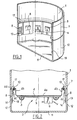
- la figure 1 est une vue partielle en perspective d'un réservoir de bouilloire conforme à un premier mode de réalisation, sans plaque de chauffe;
- la figure 2 est une vue en coupe longitudinale du réservoir de la figure 1, la plaque de chauffe étant montée dans le réservoir;
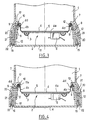
- la figure 3 est une vue analogue à la figure 2 d'un second mode de réalisation du réservoir; et
- la figure 4 est une vue analogue à la figure 3 d'un second mode de réalisation modifié du réservoir.
- Figure 1 is a partial perspective view of a kettle tank according to a first embodiment, without a heating plate;
- Figure 2 is a longitudinal sectional view of the tank of Figure 1, the heating plate being mounted in the tank;
- Figure 3 is a view similar to Figure 2 of a second embodiment of the tank; and
- Figure 4 is a view similar to Figure 3 of a second modified embodiment of the tank.
Un premier mode de réalisation va tout d'abord être décrit en référence aux figures 1 et 2.A first embodiment will first of all be described with reference to FIGS. 1 and 2.
Une bouilloire électrique comprend un réservoir 1 de liquide à chauffer, en matière plastique, généralement fermé en partie supérieure par un couvercle (non représenté).An electric kettle comprises a reservoir 1 of liquid to be heated, made of plastic material, generally closed at the top by a cover (not shown).
Un moyen de chauffe 2 comprend au moins une résistance électrique 3 associée à une plaque métallique de chauffe 4 montée à proximité du fond du réservoir 1.A heating means 2 comprises at least one
Une plaque de diffusion thermique 5 et un limiteur thermique 6 sont associés de manière connue à la plaque de chauffe 4. On pourra se reporter pour plus de détails sur le fonctionnement de ce moyen de chauffe à la demande de brevet français FR 93 09 467.A
Les parois latérales 7 du réservoir 1 comportent des moyens formant épaulement 8 adaptés à supporter un rebord périphérique 4c, 4d, de la plaque métallique de chauffe 4.The
Comme bien illustré à la figure 1, les moyens formant épaulement comprennent une série de butées 8 en saillie sur la face interne des parois latérales 7 du réservoir et réparties uniformément sur le pourtour, dans un plan transversal du réservoir 1 et à proximité du fond du réservoir.As illustrated in FIG. 1, the shoulder means comprise a series of
Le rebord périphérique de la plaque 4 comprend une aile 4c s'étendant parallèlement aux parois latérales 7 du réservoir 1 et reposant en son extrémité sur les butées 8.The peripheral rim of the
Cette aile 4c est reliée à la plaque 4 par une seconde aile 4b, s'étendant parallèlement à l'aile 4c, de sorte que la plaque 4 a sensiblement la forme d'un récipient dont le fond est constitué par la surface supérieure 4a et les bords ont une section transversale en forme de U renversé constitué par les deux ailes parallèles 4b, 4c, et une portion de liaison 4d formant la base du U.This wing 4c is connected to the
Le réservoir 1 a un fond 11 comprenant une jupe 12 adaptée à s'emboîter autour des parois latérales 7 du réservoir 1 pour retenir celles-ci comprimées autour de la plaque de chauffe 4.The tank 1 has a
La jupe 12 s'étend à partir du fond 11 du réservoir et au-delà des épaulements 8 prévus sur les parois latérales 7.The
De préférence, les parois latérales 7 ont un décrochement dans la partie inférieure du réservoir 1, de sorte que la jupe 12 vient s'emboîter autour des parois latérales 7, dans cette partie inférieure du réservoir 1, dans le prolongement de la paroi latérale 7 du reste du réservoir 1.Preferably, the
Des moyens de fixation 13, 14 sont prévus pour solidariser le fond 11 au réservoir 1.Fixing means 13, 14 are provided to secure the
De préférence, ces moyens de fixation sont réversibles, de manière à pouvoir démonter le fond 11 pour accéder et retirer la plaque de chauffe 4 pour réparation.Preferably, these fixing means are reversible, so as to be able to dismantle the
Dans cet exemple, les moyens de fixation comprennent une série de crochets 13 en saillie disposés sur la jupe 12 du fond 11 et adaptés à être insérés respectivement dans une série d'évidements 14 des parois latérales 7 du réservoir 1.In this example, the fixing means comprise a series of projecting
Ces évidements 14 sont prévus à proximité de l'extrémité inférieure des parois latérales, sous les butées 8 formant épaulement.These
Les crochets 13 et les évidements complémentaires 14 sont répartis uniformément dans un plan transversal du réservoir 1.The
Le montage de la plaque de chauffe 4 est ainsi très simple à réaliser, par "clipsage" du fond 11 autour des parois latérales 7 du réservoir 1.The mounting of the
Un joint d'étanchéité 10, tel qu'un cordon de silicone polymérisable ou d'une pièce silicone ou autre matière injectée ou découpée, est disposé entre les parois latérales 7 et la portion de liaison 4d du rebord périphérique de la plaque 4.A
Les parois latérales 7 comprennent une aile 17 s'étendant vers l'intérieur du réservoir 1, au droit du bord périphérique 4c, 4d de la plaque de chauffe 4, le joint d'étanchéité 10 étant maintenu comprimé entre l'aile 17 et le bord périphérique 4c, 4d, de la plaque 4.The
L'aile 17 s'étend parallèlement à la portion de liaison 4d du bord de la plaque de chauffe 4, le joint 10 étant intercalé entre eux.The
Dans cet exemple, et afin de maintenir en place le joint d'étanchéité 10, la portion de liaison 4d comprend un épaulement, le joint 10 étant entouré par l'aile 17, la paroi latérale 7 et cet épaulement de la portion de liaison 4d.In this example, and in order to hold the
Comme illustré à la figure 4, et à titre de variante, l'aile 17 peut comprendre, à son extrémité, un bord tombé 17a, le joint d'étanchéité 10 étant logé dans une gorge formée par la paroi latérale 7, l'aile 17 et le bord tombé 17a, et débouchant au-dessus de la portion de liaison 4d du bord de la plaque 4.As illustrated in FIG. 4, and as a variant, the
Cette gorge facilite la mise en place du joint 10 et son maintien en place, même lorsque la plaque de chauffe 4 est démontée.This groove facilitates the establishment of the
Dans les réalisations des figures 3 et 4, le montage de la plaque 4 est réalisé selon un second mode de l'invention.In the embodiments of FIGS. 3 and 4, the mounting of the
Les moyens formant épaulement comprennent une bague périphérique 9 en matière résistance à haute température supportant le rebord périphérique 4d de la plaque de chauffe 4.The shoulder means comprise a
Cette bague périphérique 9 a une section en forme de L renversé dont un bras s'étend parallèlement aux parois latérales 7 du réservoir et repose sur les butées 8 et l'autre bras supporte la portion de liaison 4d du bord de la plaque de chauffe 4.This
L'aile 4c du bord de la plaque 4 est ainsi remplacée par la bague périphérique 9, de sorte que la plaque de chauffe 4 n'est plus en contact direct avec le réservoir 1. Ce dernier peut être réalisé en une matière plastique de résistance thermique limitée, tel qu'en polypropylène, et donc à moindre coût.The wing 4c of the edge of the
Seule la bague 9 doit être susceptible de résister à des températures élevées.Only the
Dans ce second mode de réalisation, le réservoir 1 comporte en outre une portion de recouvrement 20 s'étendant sensiblement parallèlement aux parois latérales 7, la jupe 12 du fond 11 étant logée entre les parois latérales 7 et la portion de recouvrement 20 du réservoir 1.In this second embodiment, the reservoir 1 also comprises a covering
Les moyens de fixation comprennent des vis 15, la portion de recouvrement 20 comportant des alésages taraudés 21 adaptés à recevoir les vis de fixation 15.The fixing means comprise
Les vis 15 sont ainsi introduites dans une ouverture prévue dans une patte de fixation 22 solidaire du fond 11 et visées dans l'alésage 21 s'étendant parallèlement à la jupe 12 et aux parois latérales 7 du réservoir 1.The
La jupe 12 est ainsi emboîtée entre les parois latérales 7 et la portion de recouvrement 20 du réservoir 1, ce qui renforce encore la solidité de la fixation par contre-verrouillage de la plaque 4 dans le réservoir.The
Bien entendu, l'invention n'est pas limitée aux exemples décrits ci-dessus et de nombreuses modifications peuvent être apportées à ceux-ci sans sortir du cadre de l'invention.Of course, the invention is not limited to the examples described above and numerous modifications can be made to them without departing from the scope of the invention.
Ainsi, les différentes caractéristiques relatives aux moyens formant épaulement, à la fixation du joint, aux moyens de fixation... peuvent être combinées indifféremment dans des modes de réalisation différents de ceux illustrés aux figures.Thus, the various characteristics relating to the means forming the shoulder, to the fixing of the joint, to the fixing means, etc. can be combined indifferently in embodiments different from those illustrated in the figures.
Claims (8)
Applications Claiming Priority (2)
| Application Number | Priority Date | Filing Date | Title |
|---|---|---|---|
| FR9605987A FR2748645B1 (en) | 1996-05-14 | 1996-05-14 | ELECTRIC KETTLE WITH METAL PLATE OF HEATER |
| FR9605987 | 1996-05-14 |
Publications (2)
| Publication Number | Publication Date |
|---|---|
| EP0807394A1 true EP0807394A1 (en) | 1997-11-19 |
| EP0807394B1 EP0807394B1 (en) | 1999-12-22 |
Family
ID=9492115
Family Applications (1)
| Application Number | Title | Priority Date | Filing Date |
|---|---|---|---|
| EP97400983A Expired - Lifetime EP0807394B1 (en) | 1996-05-14 | 1997-04-30 | Electrical kettle with heating metallic plate |
Country Status (9)
| Country | Link |
|---|---|
| US (1) | US5908570A (en) |
| EP (1) | EP0807394B1 (en) |
| CN (1) | CN1144505C (en) |
| CA (1) | CA2205101A1 (en) |
| DE (2) | DE807394T1 (en) |
| ES (1) | ES2114520T1 (en) |
| FR (1) | FR2748645B1 (en) |
| IN (1) | IN191983B (en) |
| RU (1) | RU2176900C2 (en) |
Cited By (9)
| Publication number | Priority date | Publication date | Assignee | Title |
|---|---|---|---|---|
| WO1999063789A1 (en) * | 1998-06-03 | 1999-12-09 | Strix Limited | Liquid heating vessels |
| NL1009931C2 (en) * | 1998-08-24 | 2000-02-25 | Ferro Tech Bv | Device for heating liquids, especially kettle, contains seal radially clamped between inner wall of liquid vessel and peripheral wall of base |
| EP1002488A1 (en) * | 1998-11-17 | 2000-05-24 | Bernd Schreitmüller | Electrical boiler |
| GB2344506A (en) * | 1998-12-08 | 2000-06-14 | Otter Controls Ltd | Electrically heated vessels |
| WO2000047094A1 (en) | 1999-02-08 | 2000-08-17 | Otter Controls Limited | Improvements relating to electrically heated vessels |
| WO2000048494A1 (en) * | 1999-02-18 | 2000-08-24 | Moulinex S.A. | Electric kettle with metal heating plate |
| WO2007077105A1 (en) * | 2006-01-05 | 2007-07-12 | Arcelik Anonim Sirketi | A coffeepot |
| GB2459102A (en) * | 2008-04-08 | 2009-10-14 | Otter Controls Ltd | Mounting the heating element in a liquid heating vessel |
| EP2974630A4 (en) * | 2013-03-14 | 2016-11-09 | Zhejiang Haers Vacuum Containers Co Ltd | Vacuum electric kettle |
Families Citing this family (17)
| Publication number | Priority date | Publication date | Assignee | Title |
|---|---|---|---|---|
| FR2806283B1 (en) | 2000-03-17 | 2002-07-19 | Seb Sa | ELECTRIC KETTLE WITH METAL PLATE OF HEATER |
| NL1014983C2 (en) * | 2000-04-19 | 2001-10-24 | Ferro Tech Bv | Water kettle with handle, pouring spout and protective opening on under side, kettle base being formed by plate with central cap in which flat heating element is fitted |
| GB2363973A (en) * | 2000-06-29 | 2002-01-16 | Otter Controls Ltd | Securing planar heating element in liquid heating vessel |
| FR2817726B1 (en) | 2000-12-13 | 2003-09-12 | Seb Sa | ELECTRICAL APPARATUS WITH METAL PLATE OF HEATER FIXED UNDER A TANK |
| FR2829009B1 (en) * | 2001-09-05 | 2004-11-26 | Seb Sa | HOUSEHOLD APPLIANCE WITH HEATING DEVICE AND METHOD FOR PRODUCING SUCH A DEVICE |
| DE20119544U1 (en) | 2001-11-23 | 2002-02-21 | Fritz Eichenauer GmbH & Co. KG, 76870 Kandel | Electrically heated cooking vessel |
| CN100502741C (en) * | 2003-01-07 | 2009-06-24 | 邵志成 | Electric kettle with improved connection structure |
| FR2853411B1 (en) * | 2003-04-04 | 2006-12-08 | Actaris Sas | FLUID COUNTER IN PARTICULAR WATER METER WITH VOLUMETRIC MEASUREMENT CHAMBER |
| DE10335823A1 (en) * | 2003-08-05 | 2005-03-03 | BSH Bosch und Siemens Hausgeräte GmbH | Electrically heated cookware and method for its assembly |
| DE10335826A1 (en) * | 2003-08-05 | 2005-03-10 | Bsh Bosch Siemens Hausgeraete | Electrically heated cookware and method for its assembly |
| DE10335822A1 (en) * | 2003-08-05 | 2005-03-03 | BSH Bosch und Siemens Hausgeräte GmbH | Electrically heated cookware and method for its assembly |
| US7315692B2 (en) * | 2005-04-29 | 2008-01-01 | Hung Chow | Electrical water heater |
| FR2925275A1 (en) * | 2007-12-21 | 2009-06-26 | Seb Sa | HEATED CONTAINER AND HEATING DEVICE FOR AN ELECTRICAL APPLIANCE FOR PREPARING FOOD AND / OR BEVERAGES |
| CN202761008U (en) * | 2011-07-01 | 2013-03-06 | 皇家飞利浦电子股份有限公司 | Electric heating container and seal component for same |
| FR3005841B1 (en) * | 2013-05-21 | 2016-12-09 | Seb Sa | KETTLE COMPRISING A SEALED HOUSING |
| US9622611B2 (en) * | 2014-08-01 | 2017-04-18 | Ronald Tuan | Foldable electric kettle |
| FR3067584B1 (en) * | 2017-06-14 | 2019-08-09 | Seb S.A. | BOTTLE WITH BRAKE ELEMENT AND HOLDING OF THE COVER |
Citations (6)
| Publication number | Priority date | Publication date | Assignee | Title |
|---|---|---|---|---|
| GB2066052A (en) * | 1979-11-22 | 1981-07-08 | Gen Electric Canada | Electric kettle reservoir assembly |
| EP0285839A2 (en) * | 1987-04-07 | 1988-10-12 | E.G.O. Elektro-Geräte Blanc u. Fischer | Electric heating device |
| EP0574310A1 (en) * | 1992-06-11 | 1993-12-15 | Seb S.A. | Heating plate for a heating container, in particular for a kettle |
| FR2708407A1 (en) * | 1993-07-26 | 1995-02-03 | Seb Sa | Electric kettle comprising a simplified heating means. |
| GB2291324A (en) * | 1994-07-07 | 1996-01-17 | Pifco Ltd | Kettle for boiling small quantities of water using a non-flat bottom |
| WO1996018331A1 (en) * | 1994-12-13 | 1996-06-20 | Strix Limited | Liquid heating vessels |
Family Cites Families (4)
| Publication number | Priority date | Publication date | Assignee | Title |
|---|---|---|---|---|
| US3442199A (en) * | 1967-11-29 | 1969-05-06 | John F Mcgrail | Beverage maker |
| US3429252A (en) * | 1968-07-01 | 1969-02-25 | Angelo Colonna | Coffee maker and brewer |
| DE2443500A1 (en) * | 1974-09-11 | 1976-04-01 | Rowenta Werke Gmbh | Portable electric water heater with seal - has water tight arrangement between main vessel and heating element |
| RU2054279C1 (en) * | 1993-03-10 | 1996-02-20 | Акционерное общество "Нижегородский телевизионный завод им.В.И.Ленина" | Electric percolator |
-
1996
- 1996-05-14 FR FR9605987A patent/FR2748645B1/en not_active Expired - Lifetime
-
1997
- 1997-02-05 IN IN792CA1997 patent/IN191983B/en unknown
- 1997-04-30 DE DE0807394T patent/DE807394T1/en active Pending
- 1997-04-30 DE DE69700974T patent/DE69700974T2/en not_active Expired - Fee Related
- 1997-04-30 ES ES97400983T patent/ES2114520T1/en active Pending
- 1997-04-30 EP EP97400983A patent/EP0807394B1/en not_active Expired - Lifetime
- 1997-05-08 US US08/853,348 patent/US5908570A/en not_active Expired - Lifetime
- 1997-05-12 CA CA002205101A patent/CA2205101A1/en not_active Abandoned
- 1997-05-12 RU RU97107838/13A patent/RU2176900C2/en not_active IP Right Cessation
- 1997-05-13 CN CNB971115435A patent/CN1144505C/en not_active Expired - Lifetime
Patent Citations (6)
| Publication number | Priority date | Publication date | Assignee | Title |
|---|---|---|---|---|
| GB2066052A (en) * | 1979-11-22 | 1981-07-08 | Gen Electric Canada | Electric kettle reservoir assembly |
| EP0285839A2 (en) * | 1987-04-07 | 1988-10-12 | E.G.O. Elektro-Geräte Blanc u. Fischer | Electric heating device |
| EP0574310A1 (en) * | 1992-06-11 | 1993-12-15 | Seb S.A. | Heating plate for a heating container, in particular for a kettle |
| FR2708407A1 (en) * | 1993-07-26 | 1995-02-03 | Seb Sa | Electric kettle comprising a simplified heating means. |
| GB2291324A (en) * | 1994-07-07 | 1996-01-17 | Pifco Ltd | Kettle for boiling small quantities of water using a non-flat bottom |
| WO1996018331A1 (en) * | 1994-12-13 | 1996-06-20 | Strix Limited | Liquid heating vessels |
Cited By (13)
| Publication number | Priority date | Publication date | Assignee | Title |
|---|---|---|---|---|
| GB2354145A (en) * | 1998-06-03 | 2001-03-14 | Strix Ltd | Liquid heating vessels |
| WO1999063789A1 (en) * | 1998-06-03 | 1999-12-09 | Strix Limited | Liquid heating vessels |
| GB2354145B (en) * | 1998-06-03 | 2002-10-30 | Strix Ltd | Liquid heating vessels |
| NL1009931C2 (en) * | 1998-08-24 | 2000-02-25 | Ferro Tech Bv | Device for heating liquids, especially kettle, contains seal radially clamped between inner wall of liquid vessel and peripheral wall of base |
| EP1002488A1 (en) * | 1998-11-17 | 2000-05-24 | Bernd Schreitmüller | Electrical boiler |
| GB2344506A (en) * | 1998-12-08 | 2000-06-14 | Otter Controls Ltd | Electrically heated vessels |
| GB2344506B (en) * | 1998-12-08 | 2002-10-02 | Otter Controls Ltd | Improvements relating to electrically heated vessels |
| WO2000047094A1 (en) | 1999-02-08 | 2000-08-17 | Otter Controls Limited | Improvements relating to electrically heated vessels |
| FR2789868A1 (en) * | 1999-02-18 | 2000-08-25 | Moulinex Sa | Electric kettle has metal heating plate over element supported by skirt extending vertically inside base of cylindrical body |
| WO2000048494A1 (en) * | 1999-02-18 | 2000-08-24 | Moulinex S.A. | Electric kettle with metal heating plate |
| WO2007077105A1 (en) * | 2006-01-05 | 2007-07-12 | Arcelik Anonim Sirketi | A coffeepot |
| GB2459102A (en) * | 2008-04-08 | 2009-10-14 | Otter Controls Ltd | Mounting the heating element in a liquid heating vessel |
| EP2974630A4 (en) * | 2013-03-14 | 2016-11-09 | Zhejiang Haers Vacuum Containers Co Ltd | Vacuum electric kettle |
Also Published As
| Publication number | Publication date |
|---|---|
| CA2205101A1 (en) | 1997-11-14 |
| FR2748645A1 (en) | 1997-11-21 |
| FR2748645B1 (en) | 1998-07-24 |
| EP0807394B1 (en) | 1999-12-22 |
| CN1144505C (en) | 2004-03-31 |
| IN191983B (en) | 2004-01-31 |
| DE69700974D1 (en) | 2000-01-27 |
| DE807394T1 (en) | 1998-09-03 |
| US5908570A (en) | 1999-06-01 |
| RU2176900C2 (en) | 2001-12-20 |
| ES2114520T1 (en) | 1998-06-01 |
| DE69700974T2 (en) | 2000-05-18 |
| CN1169652A (en) | 1998-01-07 |
Similar Documents
| Publication | Publication Date | Title |
|---|---|---|
| EP0807394B1 (en) | Electrical kettle with heating metallic plate | |
| EP0044797B1 (en) | Retractable spout provided with a tamper-proof system | |
| EP2805649B1 (en) | Boiler comprising a sealed control module | |
| FR2782257A1 (en) | Pressure cooker lid safety seal; has at least one outer edge recess allowing seal to deform and release excess pressure | |
| FR3070847A1 (en) | FOOD PREPARATION AND / OR COOKING ASSEMBLY FOR HOUSEHOLD KITCHEN ROBOT | |
| EP2805650B1 (en) | Boiler comprising a sealed housing | |
| EP0786221B1 (en) | Electric kettle with heating bottom | |
| EP1154714B1 (en) | Electric kettle with metal heating plate | |
| EP3634173B1 (en) | Pot for cosmetic product | |
| FR2648694A1 (en) | REMOVABLE WATER TANK FOR HOUSEHOLD APPLIANCE AND HOUSEHOLD APPLIANCE COMPRISING SUCH A TANK | |
| FR2488200A1 (en) | CLOSING PLATE FOR A SPARE WHEEL HOUSING | |
| FR2760619A1 (en) | ELECTRIC KETTLE WITH STEAM CHANNEL LEADING TO A TEMPERATURE OR STEAM SENSOR | |
| EP1117318B1 (en) | Electrical appliance for heating liquids, comprising a heating base and glass walls | |
| FR2935305A1 (en) | REMOTE FITTING TIP FOR FUEL FILLING TUBE | |
| EP0607870B1 (en) | Steam ironing device | |
| FR2767680A1 (en) | REMOVABLE BOTTLE | |
| EP0726055B1 (en) | Electric cooking apparatus | |
| FR2629587A1 (en) | PERFECTED TYPE TRANSDUCER | |
| EP1380241B1 (en) | Pouring handle for a glass container | |
| FR3113574A3 (en) | container for cooking food provided with a thermal signaling device | |
| BE892842A (en) | Frying pan handle with integral thermometer - has suction pad with guide ring mounted on thermometer casing | |
| EP0815785B1 (en) | Lid for a cooking vessel | |
| EP1440647A1 (en) | Insulated container | |
| EP1625987B1 (en) | Hydraulic reservoir cover seal, reservoir with such a cover, and methods of assembling such a cover | |
| FR2630085A1 (en) | Lid made of synthetic material to be fitted onto a container |
Legal Events
| Date | Code | Title | Description |
|---|---|---|---|
| PUAI | Public reference made under article 153(3) epc to a published international application that has entered the european phase |
Free format text: ORIGINAL CODE: 0009012 |
|
| AK | Designated contracting states |
Kind code of ref document: A1 Designated state(s): BE DE ES GB IT NL |
|
| 17P | Request for examination filed |
Effective date: 19980306 |
|
| ITCL | It: translation for ep claims filed |
Representative=s name: BARZANO' E ZANARDO ROMA S.P.A. |
|
| 17Q | First examination report despatched |
Effective date: 19980406 |
|
| REG | Reference to a national code |
Ref country code: ES Ref legal event code: BA2A Ref document number: 2114520 Country of ref document: ES Kind code of ref document: T1 |
|
| GBC | Gb: translation of claims filed (gb section 78(7)/1977) | ||
| TCNL | Nl: translation of patent claims filed | ||
| DET | De: translation of patent claims | ||
| GRAG | Despatch of communication of intention to grant |
Free format text: ORIGINAL CODE: EPIDOS AGRA |
|
| GRAG | Despatch of communication of intention to grant |
Free format text: ORIGINAL CODE: EPIDOS AGRA |
|
| GRAH | Despatch of communication of intention to grant a patent |
Free format text: ORIGINAL CODE: EPIDOS IGRA |
|
| GRAH | Despatch of communication of intention to grant a patent |
Free format text: ORIGINAL CODE: EPIDOS IGRA |
|
| GRAA | (expected) grant |
Free format text: ORIGINAL CODE: 0009210 |
|
| AK | Designated contracting states |
Kind code of ref document: B1 Designated state(s): BE DE ES GB IT NL |
|
| PG25 | Lapsed in a contracting state [announced via postgrant information from national office to epo] |
Ref country code: NL Free format text: LAPSE BECAUSE OF FAILURE TO SUBMIT A TRANSLATION OF THE DESCRIPTION OR TO PAY THE FEE WITHIN THE PRESCRIBED TIME-LIMIT Effective date: 19991222 Ref country code: IT Free format text: LAPSE BECAUSE OF FAILURE TO SUBMIT A TRANSLATION OF THE DESCRIPTION OR TO PAY THE FEE WITHIN THE PRESCRIBED TIME-LIMIT;WARNING: LAPSES OF ITALIAN PATENTS WITH EFFECTIVE DATE BEFORE 2007 MAY HAVE OCCURRED AT ANY TIME BEFORE 2007. THE CORRECT EFFECTIVE DATE MAY BE DIFFERENT FROM THE ONE RECORDED. Effective date: 19991222 |
|
| GBT | Gb: translation of ep patent filed (gb section 77(6)(a)/1977) |
Effective date: 19991222 |
|
| REF | Corresponds to: |
Ref document number: 69700974 Country of ref document: DE Date of ref document: 20000127 |
|
| PG25 | Lapsed in a contracting state [announced via postgrant information from national office to epo] |
Ref country code: BE Free format text: LAPSE BECAUSE OF NON-PAYMENT OF DUE FEES Effective date: 20000430 |
|
| NLV1 | Nl: lapsed or annulled due to failure to fulfill the requirements of art. 29p and 29m of the patents act | ||
| PG25 | Lapsed in a contracting state [announced via postgrant information from national office to epo] |
Ref country code: ES Free format text: LAPSE BECAUSE OF FAILURE TO SUBMIT A TRANSLATION OF THE DESCRIPTION OR TO PAY THE FEE WITHIN THE PRESCRIBED TIME-LIMIT Effective date: 20000614 |
|
| PLBE | No opposition filed within time limit |
Free format text: ORIGINAL CODE: 0009261 |
|
| STAA | Information on the status of an ep patent application or granted ep patent |
Free format text: STATUS: NO OPPOSITION FILED WITHIN TIME LIMIT |
|
| BERE | Be: lapsed |
Owner name: S.A. SEB Effective date: 20000430 |
|
| 26N | No opposition filed | ||
| REG | Reference to a national code |
Ref country code: GB Ref legal event code: IF02 |
|
| PGFP | Annual fee paid to national office [announced via postgrant information from national office to epo] |
Ref country code: GB Payment date: 20060426 Year of fee payment: 10 |
|
| PGFP | Annual fee paid to national office [announced via postgrant information from national office to epo] |
Ref country code: DE Payment date: 20060427 Year of fee payment: 10 |
|
| GBPC | Gb: european patent ceased through non-payment of renewal fee |
Effective date: 20070430 |
|
| PG25 | Lapsed in a contracting state [announced via postgrant information from national office to epo] |
Ref country code: DE Free format text: LAPSE BECAUSE OF NON-PAYMENT OF DUE FEES Effective date: 20071101 |
|
| PG25 | Lapsed in a contracting state [announced via postgrant information from national office to epo] |
Ref country code: GB Free format text: LAPSE BECAUSE OF NON-PAYMENT OF DUE FEES Effective date: 20070430 |