EP0807394A1 - Elektrischer Kessel mit heizender metallischer Platte - Google Patents
Elektrischer Kessel mit heizender metallischer Platte Download PDFInfo
- Publication number
- EP0807394A1 EP0807394A1 EP97400983A EP97400983A EP0807394A1 EP 0807394 A1 EP0807394 A1 EP 0807394A1 EP 97400983 A EP97400983 A EP 97400983A EP 97400983 A EP97400983 A EP 97400983A EP 0807394 A1 EP0807394 A1 EP 0807394A1
- Authority
- EP
- European Patent Office
- Prior art keywords
- tank
- side walls
- heating plate
- kettle according
- skirt
- Prior art date
- Legal status (The legal status is an assumption and is not a legal conclusion. Google has not performed a legal analysis and makes no representation as to the accuracy of the status listed.)
- Granted
Links
- 238000010438 heat treatment Methods 0.000 title claims abstract description 41
- 230000002093 peripheral effect Effects 0.000 claims abstract description 19
- 239000002184 metal Substances 0.000 claims description 8
- 239000007788 liquid Substances 0.000 claims description 7
- 239000000463 material Substances 0.000 claims description 6
- 239000004033 plastic Substances 0.000 claims description 4
- 229920001296 polysiloxane Polymers 0.000 abstract description 3
- 230000000717 retained effect Effects 0.000 abstract 1
- 230000008439 repair process Effects 0.000 description 2
- 230000000284 resting effect Effects 0.000 description 2
- 239000004743 Polypropylene Substances 0.000 description 1
- 239000011324 bead Substances 0.000 description 1
- 230000033228 biological regulation Effects 0.000 description 1
- 230000000295 complement effect Effects 0.000 description 1
- 238000009792 diffusion process Methods 0.000 description 1
- 230000000694 effects Effects 0.000 description 1
- 230000014759 maintenance of location Effects 0.000 description 1
- 230000004048 modification Effects 0.000 description 1
- 238000012986 modification Methods 0.000 description 1
- -1 polypropylene Polymers 0.000 description 1
- 229920001155 polypropylene Polymers 0.000 description 1
- 230000002441 reversible effect Effects 0.000 description 1
Images
Classifications
-
- A—HUMAN NECESSITIES
- A47—FURNITURE; DOMESTIC ARTICLES OR APPLIANCES; COFFEE MILLS; SPICE MILLS; SUCTION CLEANERS IN GENERAL
- A47J—KITCHEN EQUIPMENT; COFFEE MILLS; SPICE MILLS; APPARATUS FOR MAKING BEVERAGES
- A47J27/00—Cooking-vessels
- A47J27/21—Water-boiling vessels, e.g. kettles
- A47J27/21008—Water-boiling vessels, e.g. kettles electrically heated
- A47J27/21041—Water-boiling vessels, e.g. kettles electrically heated with heating elements arranged outside the water vessel
Definitions
- the present invention relates to an electric kettle with a metal heating plate.
- a heating means including an electrical resistance associated with a metal heating plate which is mounted at the bottom of the tank and comes into direct contact, through its upper face, with the liquid to be heated.
- this heating plate is molded or crimped directly into the walls of the tank, near the bottom of the tank.
- French patent application 93 09 467 has described in the name of the Applicant a kettle having a heating plate resting, by means of a seal, on an internal shoulder of the tank, a central screw extending between the bottom of the tank and the center of the heating plate in order to keep the peripheral edge of the latter in contact with the gasket.
- the present invention aims to solve the aforementioned drawbacks by proposing an improved mounting system for the heating plate in the body of a kettle tank.
- the electric kettle targeted by the invention comprises a reservoir of liquid to be heated in plastic material and a heating means including at least one electrical resistance associated with a metal heating plate mounted at the bottom of the tank and in direct contact by its upper face with the liquid to be heated.
- this kettle is characterized in that the side walls of the tank include shoulder means adapted to support a peripheral rim of the metal heating plate, a seal being disposed between said side walls and the peripheral rim of the heating plate and in that the tank has a bottom comprising a skirt adapted to fit around the side walls of the tank, fixing means securing the bottom to the tank.
- the heating plate is thus held in place on the shoulder means by a counter-locking effect obtained by the skirt enclosing the side walls of the tank. Any tendency to deviate from these walls is thus carefully avoided.
- This assembly by the use of an external skirt makes it possible to make available the entire space located between the bottom of the tank and the heating plate.
- this type of assembly does not impose any shape constraint on the tank.
- the skirt extends around the side walls of the tank, from the bottom of the tank and beyond the shoulder means.
- the skirt is thus in contact with the side walls of the tank at the level of the shoulder means and has a counter-locking action directly in line with the fixing zone of the heating plate.
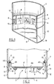
- a first embodiment will first of all be described with reference to FIGS. 1 and 2.
- An electric kettle comprises a reservoir 1 of liquid to be heated, made of plastic material, generally closed at the top by a cover (not shown).
- a heating means 2 comprises at least one electrical resistance 3 associated with a metal heating plate 4 mounted near the bottom of the tank 1.
- a thermal diffusion plate 5 and a thermal limiter 6 are associated in a known manner with the heating plate 4. Reference may be made for more details on the operation of this heating means to French patent application FR 93 09 467.
- the side walls 7 of the tank 1 include shoulder means 8 adapted to support a peripheral edge 4c, 4d, of the metal heating plate 4.
- the shoulder means comprise a series of stops 8 projecting from the internal face of the side walls 7 of the tank and distributed uniformly around the periphery, in a transverse plane of the tank 1 and near the bottom of the tank.
- the peripheral rim of the plate 4 comprises a wing 4c extending parallel to the side walls 7 of the tank 1 and resting at its end on the stops 8.
- This wing 4c is connected to the plate 4 by a second wing 4b, extending parallel to the wing 4c, so that the plate 4 has substantially the shape of a container, the bottom of which is constituted by the upper surface 4a and the edges have a cross section in the shape of an inverted U constituted by the two parallel wings 4b, 4c, and a connecting portion 4d forming the base of the U.
- the tank 1 has a bottom 11 comprising a skirt 12 adapted to fit around the side walls 7 of the tank 1 to retain these compressed around the heating plate 4.
- the skirt 12 extends from the bottom 11 of the tank and beyond the shoulders 8 provided on the side walls 7.
- the side walls 7 have a recess in the lower part of the tank 1, so that the skirt 12 comes to fit around the side walls 7, in this lower part of the tank 1, in the extension of the side wall 7 from the rest of the tank 1.
- Fixing means 13, 14 are provided to secure the bottom 11 to the tank 1.
- these fixing means are reversible, so as to be able to dismantle the base 11 to access and remove the heating plate 4 for repair.
- the fixing means comprise a series of projecting hooks 13 disposed on the skirt 12 of the bottom 11 and adapted to be inserted respectively in a series of recesses 14 in the side walls 7 of the tank 1.
- the hooks 13 and the complementary recesses 14 are distributed uniformly in a transverse plane of the reservoir 1.
- the mounting of the heating plate 4 is thus very simple to perform, by "clipping" the bottom 11 around the side walls 7 of the tank 1.
- a seal 10 such as a bead of polymerizable silicone or of a piece of silicone or other injected or cut material, is disposed between the side walls 7 and the connecting portion 4d of the peripheral rim of the plate 4.
- the side walls 7 comprise a wing 17 extending towards the inside of the tank 1, in line with the peripheral edge 4c, 4d of the heating plate 4, the seal 10 being kept compressed between the wing 17 and the peripheral edge 4c, 4d, of plate 4.
- the wing 17 extends parallel to the connecting portion 4d of the edge of the heating plate 4, the seal 10 being interposed between them.
- connection portion 4d includes a shoulder, the seal 10 being surrounded by the wing 17, the side wall 7 and this shoulder of the connecting portion 4d.
- the wing 17 may comprise, at its end, a fallen edge 17a, the seal 10 being housed in a groove formed by the side wall 7, the wing 17 and the fallen edge 17a, and opening above the connecting portion 4d from the edge of the plate 4.
- This groove facilitates the establishment of the seal 10 and its retention in place, even when the heating plate 4 is removed.
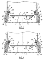
- the mounting of the plate 4 is carried out according to a second mode of the invention.
- the shoulder means comprise a peripheral ring 9 of high temperature resistance material supporting the peripheral rim 4d of the heating plate 4.
- This peripheral ring 9 has an inverted L-shaped section, one arm of which extends parallel to the side walls 7 of the tank and rests on the stops 8 and the other arm supports the connection portion 4d from the edge of the heating plate 4 .
- the wing 4c of the edge of the plate 4 is thus replaced by the peripheral ring 9, so that the heating plate 4 is no longer in direct contact with the tank 1.
- the latter can be made of a plastic of resistance limited thermal, such as polypropylene, and therefore at a lower cost.
- the reservoir 1 also comprises a covering portion 20 extending substantially parallel to the side walls 7, the skirt 12 of the bottom 11 being housed between the side walls 7 and the covering portion 20 of the reservoir 1.
- the fixing means comprise screws 15, the covering portion 20 comprising tapped bores 21 adapted to receive the fixing screws 15.
- the screws 15 are thus introduced into an opening provided in a fixing lug 22 integral with the bottom 11 and aimed in the bore 21 extending parallel to the skirt 12 and to the side walls 7 of the tank 1.
- the skirt 12 is thus fitted between the side walls 7 and the covering portion 20 of the reservoir 1, which further strengthens the solidity of the fixing by locking the plate 4 in the reservoir.
Landscapes
- Engineering & Computer Science (AREA)
- Food Science & Technology (AREA)
- Cookers (AREA)
- Details Of Rigid Or Semi-Rigid Containers (AREA)
Applications Claiming Priority (2)
| Application Number | Priority Date | Filing Date | Title |
|---|---|---|---|
| FR9605987A FR2748645B1 (fr) | 1996-05-14 | 1996-05-14 | Bouilloire electrique a plaque metallique de chauffe |
| FR9605987 | 1996-05-14 |
Publications (2)
| Publication Number | Publication Date |
|---|---|
| EP0807394A1 true EP0807394A1 (de) | 1997-11-19 |
| EP0807394B1 EP0807394B1 (de) | 1999-12-22 |
Family
ID=9492115
Family Applications (1)
| Application Number | Title | Priority Date | Filing Date |
|---|---|---|---|
| EP97400983A Expired - Lifetime EP0807394B1 (de) | 1996-05-14 | 1997-04-30 | Elektrischer Kessel mit heizender metallischer Platte |
Country Status (9)
| Country | Link |
|---|---|
| US (1) | US5908570A (de) |
| EP (1) | EP0807394B1 (de) |
| CN (1) | CN1144505C (de) |
| CA (1) | CA2205101A1 (de) |
| DE (2) | DE807394T1 (de) |
| ES (1) | ES2114520T1 (de) |
| FR (1) | FR2748645B1 (de) |
| IN (1) | IN191983B (de) |
| RU (1) | RU2176900C2 (de) |
Cited By (9)
| Publication number | Priority date | Publication date | Assignee | Title |
|---|---|---|---|---|
| WO1999063789A1 (en) * | 1998-06-03 | 1999-12-09 | Strix Limited | Liquid heating vessels |
| NL1009931C2 (nl) * | 1998-08-24 | 2000-02-25 | Ferro Tech Bv | Inrichting voor het verwarmen van vloeistof, werkwijze voor het vervaardigen van de inrichting en een hulpstuk voor toepassing bij de werkwijze. |
| EP1002488A1 (de) * | 1998-11-17 | 2000-05-24 | Bernd Schreitmüller | Elektrischer Wasserkocher |
| GB2344506A (en) * | 1998-12-08 | 2000-06-14 | Otter Controls Ltd | Electrically heated vessels |
| WO2000047094A1 (en) | 1999-02-08 | 2000-08-17 | Otter Controls Limited | Improvements relating to electrically heated vessels |
| WO2000048494A1 (fr) * | 1999-02-18 | 2000-08-24 | Moulinex S.A. | Bouilloire electrique a plaque metallique chauffante |
| WO2007077105A1 (en) * | 2006-01-05 | 2007-07-12 | Arcelik Anonim Sirketi | A coffeepot |
| GB2459102A (en) * | 2008-04-08 | 2009-10-14 | Otter Controls Ltd | Mounting the heating element in a liquid heating vessel |
| EP2974630A4 (de) * | 2013-03-14 | 2016-11-09 | Zhejiang Haers Vacuum Containers Co Ltd | Vakuumwasserkocher |
Families Citing this family (17)
| Publication number | Priority date | Publication date | Assignee | Title |
|---|---|---|---|---|
| FR2806283B1 (fr) | 2000-03-17 | 2002-07-19 | Seb Sa | Bouilloire electrique a plaque metallique de chauffe |
| NL1014983C2 (nl) * | 2000-04-19 | 2001-10-24 | Ferro Tech Bv | Koppelconstructie voor een verwarmingselement. |
| GB2363973A (en) * | 2000-06-29 | 2002-01-16 | Otter Controls Ltd | Securing planar heating element in liquid heating vessel |
| FR2817726B1 (fr) | 2000-12-13 | 2003-09-12 | Seb Sa | Appareil electrique a plaque metallique de chauffe fixee sous un reservoir |
| FR2829009B1 (fr) * | 2001-09-05 | 2004-11-26 | Seb Sa | Appareil electromenager a dispositif de chauffage et procede de realisation d'un tel dispositif |
| DE20119544U1 (de) | 2001-11-23 | 2002-02-21 | Fritz Eichenauer GmbH & Co. KG, 76870 Kandel | Elektrisch beheizbares Kochgefäß |
| CN100502741C (zh) * | 2003-01-07 | 2009-06-24 | 邵志成 | 改良连接结构的电热水壶 |
| FR2853411B1 (fr) * | 2003-04-04 | 2006-12-08 | Actaris Sas | Compteur de fluide en particulier compteur d'eau a chambre de mesure volumetrique |
| DE10335822A1 (de) * | 2003-08-05 | 2005-03-03 | BSH Bosch und Siemens Hausgeräte GmbH | Elektrisch beheizbares Kochgeschirr und Verfahren zu dessen Montage |
| DE10335823A1 (de) * | 2003-08-05 | 2005-03-03 | BSH Bosch und Siemens Hausgeräte GmbH | Elektrisch beheizbares Kochgeschirr und Verfahren zu dessen Montage |
| DE10335826A1 (de) * | 2003-08-05 | 2005-03-10 | Bsh Bosch Siemens Hausgeraete | Elektrisch beheizbares Kochgeschirr und Verfahren zu dessen Montage |
| US7315692B2 (en) * | 2005-04-29 | 2008-01-01 | Hung Chow | Electrical water heater |
| FR2925275A1 (fr) * | 2007-12-21 | 2009-06-26 | Seb Sa | Recipient chauffant et dispositif chauffant pour un appareil electromenager de preparation d'aliments et/ou de boissons |
| JP2014518122A (ja) * | 2011-07-01 | 2014-07-28 | コーニンクレッカ フィリップス エヌ ヴェ | シールを有する電気式加熱容器 |
| FR3005841B1 (fr) * | 2013-05-21 | 2016-12-09 | Seb Sa | Bouilloire comportant un boitier etanche |
| US9622611B2 (en) * | 2014-08-01 | 2017-04-18 | Ronald Tuan | Foldable electric kettle |
| FR3067584B1 (fr) * | 2017-06-14 | 2019-08-09 | Seb S.A. | Bouteille munie d'un element de frein et de maintien du couvercle |
Citations (6)
| Publication number | Priority date | Publication date | Assignee | Title |
|---|---|---|---|---|
| GB2066052A (en) * | 1979-11-22 | 1981-07-08 | Gen Electric Canada | Electric kettle reservoir assembly |
| EP0285839A2 (de) * | 1987-04-07 | 1988-10-12 | E.G.O. Elektro-Geräte Blanc u. Fischer | Elektrische Heizvorrichtung |
| EP0574310A1 (de) * | 1992-06-11 | 1993-12-15 | Seb S.A. | Heizplatte eines Kochgefässes, insbesondere für einen Kessel |
| FR2708407A1 (fr) * | 1993-07-26 | 1995-02-03 | Seb Sa | Bouilloire électrique comportant un moyen de chauffe simplifié. |
| GB2291324A (en) * | 1994-07-07 | 1996-01-17 | Pifco Ltd | Kettle for boiling small quantities of water using a non-flat bottom |
| WO1996018331A1 (en) * | 1994-12-13 | 1996-06-20 | Strix Limited | Liquid heating vessels |
Family Cites Families (4)
| Publication number | Priority date | Publication date | Assignee | Title |
|---|---|---|---|---|
| US3442199A (en) * | 1967-11-29 | 1969-05-06 | John F Mcgrail | Beverage maker |
| US3429252A (en) * | 1968-07-01 | 1969-02-25 | Angelo Colonna | Coffee maker and brewer |
| DE2443500A1 (de) * | 1974-09-11 | 1976-04-01 | Rowenta Werke Gmbh | Elektrokocher |
| RU2054279C1 (ru) * | 1993-03-10 | 1996-02-20 | Акционерное общество "Нижегородский телевизионный завод им.В.И.Ленина" | Электрокофеварка |
-
1996
- 1996-05-14 FR FR9605987A patent/FR2748645B1/fr not_active Expired - Lifetime
-
1997
- 1997-02-05 IN IN792CA1997 patent/IN191983B/en unknown
- 1997-04-30 DE DE0807394T patent/DE807394T1/de active Pending
- 1997-04-30 DE DE69700974T patent/DE69700974T2/de not_active Expired - Fee Related
- 1997-04-30 EP EP97400983A patent/EP0807394B1/de not_active Expired - Lifetime
- 1997-04-30 ES ES97400983T patent/ES2114520T1/es active Pending
- 1997-05-08 US US08/853,348 patent/US5908570A/en not_active Expired - Lifetime
- 1997-05-12 RU RU97107838/13A patent/RU2176900C2/ru not_active IP Right Cessation
- 1997-05-12 CA CA002205101A patent/CA2205101A1/en not_active Abandoned
- 1997-05-13 CN CNB971115435A patent/CN1144505C/zh not_active Expired - Lifetime
Patent Citations (6)
| Publication number | Priority date | Publication date | Assignee | Title |
|---|---|---|---|---|
| GB2066052A (en) * | 1979-11-22 | 1981-07-08 | Gen Electric Canada | Electric kettle reservoir assembly |
| EP0285839A2 (de) * | 1987-04-07 | 1988-10-12 | E.G.O. Elektro-Geräte Blanc u. Fischer | Elektrische Heizvorrichtung |
| EP0574310A1 (de) * | 1992-06-11 | 1993-12-15 | Seb S.A. | Heizplatte eines Kochgefässes, insbesondere für einen Kessel |
| FR2708407A1 (fr) * | 1993-07-26 | 1995-02-03 | Seb Sa | Bouilloire électrique comportant un moyen de chauffe simplifié. |
| GB2291324A (en) * | 1994-07-07 | 1996-01-17 | Pifco Ltd | Kettle for boiling small quantities of water using a non-flat bottom |
| WO1996018331A1 (en) * | 1994-12-13 | 1996-06-20 | Strix Limited | Liquid heating vessels |
Cited By (13)
| Publication number | Priority date | Publication date | Assignee | Title |
|---|---|---|---|---|
| GB2354145A (en) * | 1998-06-03 | 2001-03-14 | Strix Ltd | Liquid heating vessels |
| WO1999063789A1 (en) * | 1998-06-03 | 1999-12-09 | Strix Limited | Liquid heating vessels |
| GB2354145B (en) * | 1998-06-03 | 2002-10-30 | Strix Ltd | Liquid heating vessels |
| NL1009931C2 (nl) * | 1998-08-24 | 2000-02-25 | Ferro Tech Bv | Inrichting voor het verwarmen van vloeistof, werkwijze voor het vervaardigen van de inrichting en een hulpstuk voor toepassing bij de werkwijze. |
| EP1002488A1 (de) * | 1998-11-17 | 2000-05-24 | Bernd Schreitmüller | Elektrischer Wasserkocher |
| GB2344506A (en) * | 1998-12-08 | 2000-06-14 | Otter Controls Ltd | Electrically heated vessels |
| GB2344506B (en) * | 1998-12-08 | 2002-10-02 | Otter Controls Ltd | Improvements relating to electrically heated vessels |
| WO2000047094A1 (en) | 1999-02-08 | 2000-08-17 | Otter Controls Limited | Improvements relating to electrically heated vessels |
| FR2789868A1 (fr) * | 1999-02-18 | 2000-08-25 | Moulinex Sa | Bouilloire electrique a plaque metallique chauffante |
| WO2000048494A1 (fr) * | 1999-02-18 | 2000-08-24 | Moulinex S.A. | Bouilloire electrique a plaque metallique chauffante |
| WO2007077105A1 (en) * | 2006-01-05 | 2007-07-12 | Arcelik Anonim Sirketi | A coffeepot |
| GB2459102A (en) * | 2008-04-08 | 2009-10-14 | Otter Controls Ltd | Mounting the heating element in a liquid heating vessel |
| EP2974630A4 (de) * | 2013-03-14 | 2016-11-09 | Zhejiang Haers Vacuum Containers Co Ltd | Vakuumwasserkocher |
Also Published As
| Publication number | Publication date |
|---|---|
| FR2748645A1 (fr) | 1997-11-21 |
| ES2114520T1 (es) | 1998-06-01 |
| US5908570A (en) | 1999-06-01 |
| CN1144505C (zh) | 2004-03-31 |
| DE69700974D1 (de) | 2000-01-27 |
| RU2176900C2 (ru) | 2001-12-20 |
| FR2748645B1 (fr) | 1998-07-24 |
| CA2205101A1 (en) | 1997-11-14 |
| DE807394T1 (de) | 1998-09-03 |
| IN191983B (de) | 2004-01-31 |
| DE69700974T2 (de) | 2000-05-18 |
| EP0807394B1 (de) | 1999-12-22 |
| CN1169652A (zh) | 1998-01-07 |
Similar Documents
| Publication | Publication Date | Title |
|---|---|---|
| EP0807394B1 (de) | Elektrischer Kessel mit heizender metallischer Platte | |
| EP0044797B1 (de) | Einstülpbare Ausgiesstülle mit Garantieanordnung | |
| FR2820120A1 (fr) | Bouchon avec orifice verseur ferme par un couvercle et systeme d'inviolabilite du couvercle | |
| EP2805649B1 (de) | Kochtopf, der ein dichtes Steuermodul umfasst | |
| FR2782257A1 (fr) | Joint indexe pour autocuiseur, et autocuiseur equipe d'un tel joint | |
| FR3070847A1 (fr) | Ensemble de preparation et/ou de cuisson d’aliments pour robot menager de cuisine | |
| EP1154714B1 (de) | Wasserkocher mit heizplatte aus metall | |
| EP2805650A1 (de) | Kochtopf, der ein dichtes Gehäuse umfasst | |
| EP3634173B1 (de) | Tiegel für kosmetikprodukt | |
| FR2648694A1 (fr) | Reservoir d'eau amovible pour appareil menager et appareil menager comportant un tel reservoir | |
| FR2488200A1 (fr) | Plaque de fermeture pour un logement de roue de rechange | |
| FR2760619A1 (fr) | Bouilloire electrique avec canal a vapeur menant vers un detecteur de temperature ou de vapeur | |
| EP1117318B1 (de) | Elektrogerät zum erhitzen von flüssigkeiten mit einem heizboden und glaswänden | |
| FR2806283A1 (fr) | Bouilloire electrique a plaque metallique de chauffe | |
| FR2935305A1 (fr) | Embout detrompeur pour tubulure de remplissage en carburant | |
| EP1093839B1 (de) | Filtergehäuse das einen Schraubdeckel mit Schnappverbindung aufweist | |
| EP0607870B1 (de) | Dampfbügelvorrichtung | |
| FR2767680A1 (fr) | Biberon a fond amovible | |
| EP0726055B1 (de) | Elektrisches Kochgerät | |
| FR2629587A1 (fr) | Transducteur de type perfectionne | |
| EP1380241B1 (de) | Gussgriff für einen Glasbehälter | |
| FR3113574A3 (fr) | récipient pour cuire un aliment muni d'un dispositif de signalisation thermique | |
| BE892842A (fr) | Poignee amovible a thermometre pour couvercle de poeles sauteuses | |
| EP0815785B1 (de) | Deckel für ein Kochgefäss | |
| EP1440647A1 (de) | Isoliergefäss |
Legal Events
| Date | Code | Title | Description |
|---|---|---|---|
| PUAI | Public reference made under article 153(3) epc to a published international application that has entered the european phase |
Free format text: ORIGINAL CODE: 0009012 |
|
| AK | Designated contracting states |
Kind code of ref document: A1 Designated state(s): BE DE ES GB IT NL |
|
| 17P | Request for examination filed |
Effective date: 19980306 |
|
| ITCL | It: translation for ep claims filed |
Representative=s name: BARZANO' E ZANARDO ROMA S.P.A. |
|
| 17Q | First examination report despatched |
Effective date: 19980406 |
|
| REG | Reference to a national code |
Ref country code: ES Ref legal event code: BA2A Ref document number: 2114520 Country of ref document: ES Kind code of ref document: T1 |
|
| GBC | Gb: translation of claims filed (gb section 78(7)/1977) | ||
| TCNL | Nl: translation of patent claims filed | ||
| DET | De: translation of patent claims | ||
| GRAG | Despatch of communication of intention to grant |
Free format text: ORIGINAL CODE: EPIDOS AGRA |
|
| GRAG | Despatch of communication of intention to grant |
Free format text: ORIGINAL CODE: EPIDOS AGRA |
|
| GRAH | Despatch of communication of intention to grant a patent |
Free format text: ORIGINAL CODE: EPIDOS IGRA |
|
| GRAH | Despatch of communication of intention to grant a patent |
Free format text: ORIGINAL CODE: EPIDOS IGRA |
|
| GRAA | (expected) grant |
Free format text: ORIGINAL CODE: 0009210 |
|
| AK | Designated contracting states |
Kind code of ref document: B1 Designated state(s): BE DE ES GB IT NL |
|
| PG25 | Lapsed in a contracting state [announced via postgrant information from national office to epo] |
Ref country code: NL Free format text: LAPSE BECAUSE OF FAILURE TO SUBMIT A TRANSLATION OF THE DESCRIPTION OR TO PAY THE FEE WITHIN THE PRESCRIBED TIME-LIMIT Effective date: 19991222 Ref country code: IT Free format text: LAPSE BECAUSE OF FAILURE TO SUBMIT A TRANSLATION OF THE DESCRIPTION OR TO PAY THE FEE WITHIN THE PRESCRIBED TIME-LIMIT;WARNING: LAPSES OF ITALIAN PATENTS WITH EFFECTIVE DATE BEFORE 2007 MAY HAVE OCCURRED AT ANY TIME BEFORE 2007. THE CORRECT EFFECTIVE DATE MAY BE DIFFERENT FROM THE ONE RECORDED. Effective date: 19991222 |
|
| GBT | Gb: translation of ep patent filed (gb section 77(6)(a)/1977) |
Effective date: 19991222 |
|
| REF | Corresponds to: |
Ref document number: 69700974 Country of ref document: DE Date of ref document: 20000127 |
|
| PG25 | Lapsed in a contracting state [announced via postgrant information from national office to epo] |
Ref country code: BE Free format text: LAPSE BECAUSE OF NON-PAYMENT OF DUE FEES Effective date: 20000430 |
|
| NLV1 | Nl: lapsed or annulled due to failure to fulfill the requirements of art. 29p and 29m of the patents act | ||
| PG25 | Lapsed in a contracting state [announced via postgrant information from national office to epo] |
Ref country code: ES Free format text: LAPSE BECAUSE OF FAILURE TO SUBMIT A TRANSLATION OF THE DESCRIPTION OR TO PAY THE FEE WITHIN THE PRESCRIBED TIME-LIMIT Effective date: 20000614 |
|
| PLBE | No opposition filed within time limit |
Free format text: ORIGINAL CODE: 0009261 |
|
| STAA | Information on the status of an ep patent application or granted ep patent |
Free format text: STATUS: NO OPPOSITION FILED WITHIN TIME LIMIT |
|
| BERE | Be: lapsed |
Owner name: S.A. SEB Effective date: 20000430 |
|
| 26N | No opposition filed | ||
| REG | Reference to a national code |
Ref country code: GB Ref legal event code: IF02 |
|
| PGFP | Annual fee paid to national office [announced via postgrant information from national office to epo] |
Ref country code: GB Payment date: 20060426 Year of fee payment: 10 |
|
| PGFP | Annual fee paid to national office [announced via postgrant information from national office to epo] |
Ref country code: DE Payment date: 20060427 Year of fee payment: 10 |
|
| GBPC | Gb: european patent ceased through non-payment of renewal fee |
Effective date: 20070430 |
|
| PG25 | Lapsed in a contracting state [announced via postgrant information from national office to epo] |
Ref country code: DE Free format text: LAPSE BECAUSE OF NON-PAYMENT OF DUE FEES Effective date: 20071101 |
|
| PG25 | Lapsed in a contracting state [announced via postgrant information from national office to epo] |
Ref country code: GB Free format text: LAPSE BECAUSE OF NON-PAYMENT OF DUE FEES Effective date: 20070430 |