EP0726055B1 - Elektrisches Kochgerät - Google Patents
Elektrisches Kochgerät Download PDFInfo
- Publication number
- EP0726055B1 EP0726055B1 EP96400167A EP96400167A EP0726055B1 EP 0726055 B1 EP0726055 B1 EP 0726055B1 EP 96400167 A EP96400167 A EP 96400167A EP 96400167 A EP96400167 A EP 96400167A EP 0726055 B1 EP0726055 B1 EP 0726055B1
- Authority
- EP
- European Patent Office
- Prior art keywords
- lid
- cooking appliance
- appliance according
- joint
- electrical cooking
- Prior art date
- Legal status (The legal status is an assumption and is not a legal conclusion. Google has not performed a legal analysis and makes no representation as to the accuracy of the status listed.)
- Expired - Lifetime
Links
Images

Classifications
-
- A—HUMAN NECESSITIES
- A47—FURNITURE; DOMESTIC ARTICLES OR APPLIANCES; COFFEE MILLS; SPICE MILLS; SUCTION CLEANERS IN GENERAL
- A47J—KITCHEN EQUIPMENT; COFFEE MILLS; SPICE MILLS; APPARATUS FOR MAKING BEVERAGES
- A47J37/00—Baking; Roasting; Grilling; Frying
- A47J37/12—Deep fat fryers, e.g. for frying fish or chips
- A47J37/1276—Constructional details
- A47J37/128—Integrated lids or covers
Definitions
- the present invention relates to electric cooking appliances comprising a housing containing a tank heated by a heating means and equipped with a cover mounted hinged on the upper edge of the housing and capable of occupying a closed position of the tank.
- the object of the invention is to produce a seal which overcomes the drawbacks mentioned above.
- the seal comprises a part forming a foot fixed between the peripheral edge of the counter-cover and the internal wall of the cover and an external lip arranged between the tubular part and the descending edge of the cover, and extending downwards. beyond the plane containing the lower surface of the tubular part until it comes to bear on said falling edge.
- the free end of the lip comes into contact with the internal face of the edge of the descending cover.
- the tank comprises a basket equipped with a projecting handle
- the cover has at its periphery a notch for passage of the handle, the seal is formed by an extruded profile, the ends of which are fixed to a molded part forming a seal.
- the cut edge of the notch generally has an angular profile which causes folds and / or crimps in the seal and the lip and hence leaks at the corners and the lip on the cover.
- the profiled seal is preserved from any abrupt bend and the lip can therefore be applied without folds over practically the entire periphery of the descending edge of the cover, and at the level of the notch, forming a joint perfectly fits the outline of the notch.
- FIG. 1 schematically illustrates a fryer comprising a housing 1 containing a tank 2 heated by a heating means 3 such as an armored resistor and comprising a basket 4 adapted to rest on the upper edge 5 of the tank and equipped with a handle 6 projecting outwards, as well as a cover 7 mounted articulated on the upper edge 8 of the housing 1 by means of a hinge not shown and capable of occupying a closed position of the tank 2 ( Figure 1) in particular during a frying preparation.
- the tank and the cover have a circular outline, but it could of course be rectangular.
- the cover 7 has a falling edge 9 and a counter-cover 10 fixed for example by screws 11 to the internal wall 12 of the cover 7.
- the cover is equipped with a seal 13 comprising a part tubular 14 which is intended to come to rest, when the cover is in the closed position, on the upper edge 5 of the tank 2 or, in the presence of basket 4, on the upper edge of this basket, and which is connected to a part 16 forming a foot fixed between the peripheral edge 17 of the counter-cover 10 and the internal wall 12 of the cover 7.
- the cover 7 contains a filter cartridge 18 interposed in a compartment 19 formed between the counter-cover 10 and the internal wall 12.
- the housing 1 and the cover 7 are made of a plastic material capable of degrading at a high temperature such as, for example, polypropylene.
- the seal 13 also comprises an external lip 20 arranged between the tubular part 14 and the descending edge 9 of the cover 7 and extending downwards, beyond the plane P containing the lower surface of the part tubular 14, in the direction of said descending edge 9.
- the free end 21 of the lip 20 comes into contact with the face of the internal wall 12 of the descending edge 9 of the cover 7.
- the seal 13 is an extruded profile produced continuously and capable of being cut lengthwise to adapt to the different peripheries of the cooking vessels manufactured.
- the lip 20 is implanted on the external periphery of the tubular part 14.
- the seal 13 is made of a high temperature silicone.
- the seal 13 and in particular of the lip 20 one obtains, on the one hand, a good seal between the internal wall 12 of the cover 7 and the counter-cover 10 thus preventing steam from entering the space E and hence the formation of droplets of condensation which may occur in contact with the cold wall 12 of the cover, as well as vapor leaks which are not filtered by the cartridge 18, and on the other hand, in the event of the wrong position of the cover 7 with respect to the tank 2, dangerous direct contact of the edge 5 against the falling edge 9 is avoided and therefore the creation of a hot spot capable, in the case of a metal cover, of causing burns to the user, and in the case of a polypropylene cover, to melt the corresponding joint region of the cover 7.
- the upper edge 5 of the tank may have a hook shape as illustrated or a flat shape identical to that of the basket 4.
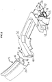
- the handle 6 projects outwardly through a passage notch 22 formed in the descending peripheral edge 9 of the cover 7. Due to this notch, the seal 13 can no longer extend over the entire periphery of the edge 5 of the tank 2 and the invention therefore provides to overcome this drawback, on the one hand, by making the seal 13 in a section whose ends 24 and 25 (Figure 2) extend to the lateral edges of the notch 22 and, on the other hand, by equipping the edge of said notch with a molded part 26 forming a seal and made of high temperature silicone.
- This molded part 26 follows the edge of the notch and, as Figure 2, has the shape of a U whose side branches 28 have tabs 30 for fixing the ends 24 and 25 of the seal 13. This fixing is preferably obtained by gluing.
- the profiled seal 13 extends practically over the entire periphery of the edge 5 of the tank 2 with the lip correctly applied, that is to say without crimping, against the falling edge 9, and the molded part 26 forms a joint perfectly matching the angular contour of the notch without also forming a fold and can thus by its underside 32 come to be applied correctly on a counter-joint 34 carried by the base of the handle 6 therefore constituting a perfect seal against level.
Landscapes
- Engineering & Computer Science (AREA)
- Food Science & Technology (AREA)
- Frying-Pans Or Fryers (AREA)
- Cookers (AREA)
Claims (10)
- Elektrisches Kochgerät mit einem Gehäuse (1), das einen durch ein Heizelement (3) beheizten Topf (2) umschließt und mit einem am oberen Rand (8) des Gehäuses angelenkten Deckel ausgestattet ist, der eine den Topf verschließende Stellung einnehmen kann, wobei der Deckel einen heruntergezogenen Rand (9) und einen Gegendeckel (10), der an der Innenwand (12) des Deckels (7) befestigt ist, sowie eine Dichtung (13) aufweist, die einen schlauchförmigen Teil (14) aufweist, der auf dem oberen Rand (5) des Topfes ruht, wenn der Deckel seine Verschlußstellung einnimmt, dadurch gekennzeichnet, daß die Dichtung (13) mit einem einen Fuß bildenden Teil (16) verbunden ist, das zwischen dem Umfangsrand (17) des Gegendeckels (10) und der Innenwand (12) des Deckels befestigt ist, und eine äußere Lippe (20) aufweist, die zwischen dem schlauchförmigen Teil (14) und dem heruntergezogenen Rand (9) des Deckels (7) angeordnet ist und sich nach unten über die Ebene P hinaus, welche die untere Fläche des schlauchförmigen Teils (14) enthält, in Richtung auf den heruntergezogenen Rand (9) erstreckt.
- Elektrisches Kochgerät nach Anspruch 1, dadurch gekennzeichnet, daß die Dichtung (13) ein Strangpreßprofil ist.
- Elektrisches Kochgerät nach Anspruch 1 oder 2, dadurch gekennzeichnet, daß die Lippe (20) an den Außenumfang des schlauchförmigen Teils (14) angesetzt ist.
- Elektrisches Kochgerät nach einem der vorangehenden Ansprüche, dadurch gekennzeichnet, daß das freie Ende (21) der Lippe (20) in Kontakt mit der Innenfläche (12) des heruntergezogenen Randes (9) des Deckels (7) kommt.
- Elektrisches Kochgerät nach den Ansprüchen 2 und 3 oder 4, worin der Topf (2) einen Korb (4) mit einem hervorstehenden Griff (6) und der Deckel (7) in seinem Unfang eine Ausnehmung (22) zum Durchtritt des Griffs aufweist, dadurch gekennzeichnet, daß die Ausnehmung (22) mit einem Formstück (26) ausgestattet ist, welches eine Dichtung bildet und sich an die Form des herausgeschnittenen Randes der Ausnehmung anpaßt, und daß die Profildichtung (13) aus einem Teilstück besteht, dessen Enden (24, 25) am Formstück (26) befestigt sind.
- Elektrisches Kochgerät nach Anspruch 5, dadurch gekennzeichnet, daß das die Dichtung bildende Formstück (26) Nasen (30) aufweist und die Enden der Dichtung (13) jeweils durch Kleben an diesen Nasen befestigt sind.
- Elektrisches Kochgerät nach Anspruch 6, dadurch gekennzeichnet, daß das die Dichtung bildende Formstück (26) aus einem Hochtemperatur-Silikon geformt ist.
- Elektrisches Kochgerät nach einem der vorangehenden Ansprüche, dadurch gekennzeichnet, daß der Deckel (7) aus einem Kunststoffmaterial gebildet ist, das bei hohen Temperaturen unbeständig ist.
- Elektrisches Kochgerät nach einem der vorangehenden Ansprüche, dadurch gekennzeichnet, daß es eine Friteuse darstellt.
- Elektrisches Kochgerät nach Anspruch 9, dadurch gekennzeichnet, daß der Deckel (7) einen Geruchsfilter (18) aufweist, der zwischen dem Gegendeckel (10) und der Innenwand (12) des Deckels (7) angeordnet ist.
Applications Claiming Priority (2)
| Application Number | Priority Date | Filing Date | Title |
|---|---|---|---|
| FR9501465A FR2730152B1 (fr) | 1995-02-08 | 1995-02-08 | Appareil electrique de cuisson |
| FR9501465 | 1995-02-08 |
Publications (2)
| Publication Number | Publication Date |
|---|---|
| EP0726055A1 EP0726055A1 (de) | 1996-08-14 |
| EP0726055B1 true EP0726055B1 (de) | 1997-10-29 |
Family
ID=9475959
Family Applications (1)
| Application Number | Title | Priority Date | Filing Date |
|---|---|---|---|
| EP96400167A Expired - Lifetime EP0726055B1 (de) | 1995-02-08 | 1996-01-24 | Elektrisches Kochgerät |
Country Status (4)
| Country | Link |
|---|---|
| EP (1) | EP0726055B1 (de) |
| DE (1) | DE69600085T2 (de) |
| ES (1) | ES2108589T3 (de) |
| FR (1) | FR2730152B1 (de) |
Families Citing this family (1)
| Publication number | Priority date | Publication date | Assignee | Title |
|---|---|---|---|---|
| FR2750312B1 (fr) * | 1996-06-27 | 1998-12-24 | Moulinex Sa | Couvercle d'appareil de cuisson |
Family Cites Families (5)
| Publication number | Priority date | Publication date | Assignee | Title |
|---|---|---|---|---|
| FR1517736A (fr) * | 1966-07-21 | 1968-03-22 | Seb Sa | Friteuse domestique |
| BE791213A (fr) * | 1972-04-17 | 1973-03-01 | Matsushita Electric Ind Co Ltd | Friteuse |
| FR2239224B1 (de) * | 1973-08-02 | 1976-06-18 | Seb Ste Emboutissage Bourgogne | |
| DE3103450C2 (de) * | 1981-02-02 | 1983-01-13 | Melitta-Werke Bentz & Sohn, 4950 Minden | Friteuse mit einem Sichtfenster-Deckel |
| GB9217090D0 (en) * | 1992-08-12 | 1992-09-23 | Morphy Ltd Richards | Fryers |
-
1995
- 1995-02-08 FR FR9501465A patent/FR2730152B1/fr not_active Expired - Fee Related
-
1996
- 1996-01-24 EP EP96400167A patent/EP0726055B1/de not_active Expired - Lifetime
- 1996-01-24 DE DE69600085T patent/DE69600085T2/de not_active Expired - Fee Related
- 1996-01-24 ES ES96400167T patent/ES2108589T3/es not_active Expired - Lifetime
Also Published As
| Publication number | Publication date |
|---|---|
| FR2730152A1 (fr) | 1996-08-09 |
| ES2108589T3 (es) | 1997-12-16 |
| FR2730152B1 (fr) | 1998-06-19 |
| DE69600085D1 (de) | 1997-12-04 |
| EP0726055A1 (de) | 1996-08-14 |
| DE69600085T2 (de) | 1998-03-05 |
Similar Documents
| Publication | Publication Date | Title |
|---|---|---|
| EP0807394B1 (de) | Elektrischer Kessel mit heizender metallischer Platte | |
| FR3070847B1 (fr) | Ensemble de preparation et/ou de cuisson d’aliments pour robot menager de cuisine | |
| WO1996004832A1 (fr) | Appareil de chauffe pour aliments, en particulier pour la realisation de fritures, comportant une contre-cuve | |
| EP2434933A2 (de) | Elektrhaushaltsgerät für speisenzubereitung mit eienr basis zur aufnahme eines arbeitsgefässes mit einer wärmeplatte | |
| EP3184007B1 (de) | Verstärkter schnellkochtopf | |
| FR2744001A1 (fr) | Bouilloire electrique a fond chauffant | |
| EP0726055B1 (de) | Elektrisches Kochgerät | |
| EP1117318B1 (de) | Elektrogerät zum erhitzen von flüssigkeiten mit einem heizboden und glaswänden | |
| EP1154714B1 (de) | Wasserkocher mit heizplatte aus metall | |
| EP1941819B1 (de) | Kochgerät | |
| EP0460618B1 (de) | Elektrischer Wasserkessel | |
| EP1557120B1 (de) | Haube von einem elektronischen Waffeleisen | |
| EP1032296B1 (de) | Druckkochgerät mit mitteln zum unterstützen eines kochbehälters in einer erhöhten position | |
| EP1795096B1 (de) | Gargerät | |
| FR2629587A1 (fr) | Transducteur de type perfectionne | |
| FR2614400A1 (fr) | Appareil autonome de cuisson par rayonnement | |
| FR2829907A1 (fr) | Yaourtiere menagere | |
| FR3070587A1 (fr) | Ustensile de cuisine | |
| EP2000066B1 (de) | Medium zum Kochen einer kleinen Menge an Lebensmitteln | |
| FR2713465A1 (fr) | Capteur CTN sur support souple pour gril-viande. | |
| FR2728450A3 (fr) | Appareil pour chauffer des liquides | |
| FR2645515A1 (fr) | Couvercle etanche, notamment pour bac a egouttures de citerne routiere | |
| FR2711500A1 (fr) | Friteuse électrique. | |
| CH495736A (fr) | Gril électrique pour aliments | |
| FR2775883A1 (fr) | Appareil a infuser |
Legal Events
| Date | Code | Title | Description |
|---|---|---|---|
| PUAI | Public reference made under article 153(3) epc to a published international application that has entered the european phase |
Free format text: ORIGINAL CODE: 0009012 |
|
| AK | Designated contracting states |
Kind code of ref document: A1 Designated state(s): BE DE ES GB IT NL |
|
| GRAG | Despatch of communication of intention to grant |
Free format text: ORIGINAL CODE: EPIDOS AGRA |
|
| 17P | Request for examination filed |
Effective date: 19970129 |
|
| GRAH | Despatch of communication of intention to grant a patent |
Free format text: ORIGINAL CODE: EPIDOS IGRA |
|
| 17Q | First examination report despatched |
Effective date: 19970324 |
|
| GRAH | Despatch of communication of intention to grant a patent |
Free format text: ORIGINAL CODE: EPIDOS IGRA |
|
| GRAA | (expected) grant |
Free format text: ORIGINAL CODE: 0009210 |
|
| AK | Designated contracting states |
Kind code of ref document: B1 Designated state(s): BE DE ES GB IT NL |
|
| GBT | Gb: translation of ep patent filed (gb section 77(6)(a)/1977) |
Effective date: 19971031 |
|
| REF | Corresponds to: |
Ref document number: 69600085 Country of ref document: DE Date of ref document: 19971204 |
|
| REG | Reference to a national code |
Ref country code: ES Ref legal event code: FG2A Ref document number: 2108589 Country of ref document: ES Kind code of ref document: T3 |
|
| ITF | It: translation for a ep patent filed |
Owner name: FUMERO BREVETTI S.N.C. |
|
| PLBE | No opposition filed within time limit |
Free format text: ORIGINAL CODE: 0009261 |
|
| STAA | Information on the status of an ep patent application or granted ep patent |
Free format text: STATUS: NO OPPOSITION FILED WITHIN TIME LIMIT |
|
| 26N | No opposition filed | ||
| REG | Reference to a national code |
Ref country code: GB Ref legal event code: IF02 |
|
| NLS | Nl: assignments of ep-patents |
Owner name: SEB S.A. |
|
| REG | Reference to a national code |
Ref country code: ES Ref legal event code: PC2A |
|
| REG | Reference to a national code |
Ref country code: GB Ref legal event code: 732E |
|
| PG25 | Lapsed in a contracting state [announced via postgrant information from national office to epo] |
Ref country code: IT Free format text: LAPSE BECAUSE OF NON-PAYMENT OF DUE FEES;WARNING: LAPSES OF ITALIAN PATENTS WITH EFFECTIVE DATE BEFORE 2007 MAY HAVE OCCURRED AT ANY TIME BEFORE 2007. THE CORRECT EFFECTIVE DATE MAY BE DIFFERENT FROM THE ONE RECORDED. Effective date: 20050124 |
|
| PGFP | Annual fee paid to national office [announced via postgrant information from national office to epo] |
Ref country code: NL Payment date: 20080131 Year of fee payment: 13 |
|
| PGFP | Annual fee paid to national office [announced via postgrant information from national office to epo] |
Ref country code: BE Payment date: 20080312 Year of fee payment: 13 |
|
| PGFP | Annual fee paid to national office [announced via postgrant information from national office to epo] |
Ref country code: ES Payment date: 20090105 Year of fee payment: 14 |
|
| PGFP | Annual fee paid to national office [announced via postgrant information from national office to epo] |
Ref country code: DE Payment date: 20090212 Year of fee payment: 14 |
|
| PGFP | Annual fee paid to national office [announced via postgrant information from national office to epo] |
Ref country code: GB Payment date: 20081201 Year of fee payment: 14 |
|
| NLV4 | Nl: lapsed or anulled due to non-payment of the annual fee |
Effective date: 20090801 |
|
| PG25 | Lapsed in a contracting state [announced via postgrant information from national office to epo] |
Ref country code: NL Free format text: LAPSE BECAUSE OF NON-PAYMENT OF DUE FEES Effective date: 20090801 |
|
| PG25 | Lapsed in a contracting state [announced via postgrant information from national office to epo] |
Ref country code: BE Free format text: LAPSE BECAUSE OF NON-PAYMENT OF DUE FEES Effective date: 20090131 |
|
| GBPC | Gb: european patent ceased through non-payment of renewal fee |
Effective date: 20100124 |
|
| PG25 | Lapsed in a contracting state [announced via postgrant information from national office to epo] |
Ref country code: DE Free format text: LAPSE BECAUSE OF NON-PAYMENT OF DUE FEES Effective date: 20100803 |
|
| PG25 | Lapsed in a contracting state [announced via postgrant information from national office to epo] |
Ref country code: GB Free format text: LAPSE BECAUSE OF NON-PAYMENT OF DUE FEES Effective date: 20100124 |
|
| REG | Reference to a national code |
Ref country code: ES Ref legal event code: FD2A Effective date: 20110224 |
|
| PG25 | Lapsed in a contracting state [announced via postgrant information from national office to epo] |
Ref country code: ES Free format text: LAPSE BECAUSE OF NON-PAYMENT OF DUE FEES Effective date: 20110223 |
|
| PG25 | Lapsed in a contracting state [announced via postgrant information from national office to epo] |
Ref country code: ES Free format text: LAPSE BECAUSE OF NON-PAYMENT OF DUE FEES Effective date: 20100125 |