EP0726055B1 - Electric cooking apparatus - Google Patents
Electric cooking apparatus Download PDFInfo
- Publication number
- EP0726055B1 EP0726055B1 EP96400167A EP96400167A EP0726055B1 EP 0726055 B1 EP0726055 B1 EP 0726055B1 EP 96400167 A EP96400167 A EP 96400167A EP 96400167 A EP96400167 A EP 96400167A EP 0726055 B1 EP0726055 B1 EP 0726055B1
- Authority
- EP
- European Patent Office
- Prior art keywords
- lid
- cooking appliance
- appliance according
- joint
- electrical cooking
- Prior art date
- Legal status (The legal status is an assumption and is not a legal conclusion. Google has not performed a legal analysis and makes no representation as to the accuracy of the status listed.)
- Expired - Lifetime
Links
Images

Classifications
-
- A—HUMAN NECESSITIES
- A47—FURNITURE; DOMESTIC ARTICLES OR APPLIANCES; COFFEE MILLS; SPICE MILLS; SUCTION CLEANERS IN GENERAL
- A47J—KITCHEN EQUIPMENT; COFFEE MILLS; SPICE MILLS; APPARATUS FOR MAKING BEVERAGES
- A47J37/00—Baking; Roasting; Grilling; Frying
- A47J37/12—Deep fat fryers, e.g. for frying fish or chips
- A47J37/1276—Constructional details
- A47J37/128—Integrated lids or covers
Landscapes
- Engineering & Computer Science (AREA)
- Food Science & Technology (AREA)
- Cookers (AREA)
- Frying-Pans Or Fryers (AREA)
Description
La présente invention se rapporte aux appareils électriques de cuisson comprenant un boîtier renfermant une cuve chauffée par un moyen de chauffage et équipée d'un couvercle monté articulé sur le bord supérieur du boîtier et susceptible d'occuper une position de fermeture de la cuve.The present invention relates to electric cooking appliances comprising a housing containing a tank heated by a heating means and equipped with a cover mounted hinged on the upper edge of the housing and capable of occupying a closed position of the tank.
Elle concerne plus précisément les appareils dans lesquels le couvercle comporte un bord descendant et un contre-couvercle fixé à distance de la paroi interne du couvercle, ainsi qu'un joint d'étanchéité comportant une partie tubulaire destinée à venir reposer sur le bord supérieur de la cuve lorsque le couvercle est en position de fermeture. Un tel appareil est connu du document FR-A-1 517 736.It relates more precisely to devices in which the cover has a descending edge and a counter-cover fixed at a distance from the internal wall of the cover, as well as a seal comprising a tubular part intended to come to rest on the upper edge of the tank when the cover is in the closed position. Such an apparatus is known from document FR-A-1,517,736.
Dans de tels appareils, il est important de garantir l'étanchéité entre la cuve et le couvercle malgré les tolérances de fabrication en grande série admises pour les différentes pièces constituant le couvercle et le boîtier. Malheureusement, il s'avère, qu'après un long usage de l'appareil, l'articulation du couvercle sur le boîtier présente des jeux indésirables qui se traduisent souvent par une non-superposition du joint sur le bord supérieur de la cuve, entraînant, d'une part, une perte d'étanchéité entre cuve et couvercle, et, d'autre part, un rapprochement d'une région du bord de cuve vers le bord descendant du couvercle occasionnant sur le couvercle un point de température élevé.In such devices, it is important to guarantee the seal between the tank and the cover despite the mass production tolerances allowed for the various parts constituting the cover and the housing. Unfortunately, it turns out that after long use of the device, the articulation of the cover on the housing presents undesirable clearances which often result in a non-overlapping of the seal on the upper edge of the tank, causing , on the one hand, a loss of tightness between the tank and the cover, and, on the other hand, an approximation of a region from the edge of the tank to the downward edge of the cover causing a high temperature point on the cover.
L'invention a pour but de réaliser un joint qui pallie les inconvénients cités ci-dessus.The object of the invention is to produce a seal which overcomes the drawbacks mentioned above.
Selon l'invention, le joint comporte une partie formant pied fixée entre le bord périphérique du contre-couvercle et la paroi interne du couvercle et une lèvre externe agencée entre la partie tubulaire et le bord descendant du couvercle, et s'étendant vers le bas au-delà du plan contenant la surface inférieure de la partie tubulaire jusqu'à venir en appui sur ledit bord descendant.According to the invention, the seal comprises a part forming a foot fixed between the peripheral edge of the counter-cover and the internal wall of the cover and an external lip arranged between the tubular part and the descending edge of the cover, and extending downwards. beyond the plane containing the lower surface of the tubular part until it comes to bear on said falling edge.
Selon une caractéristique importante de l'invention, l'extrémité libre de la lèvre vient au contact de la face interne du bord du couvercle descendant.According to an important characteristic of the invention, the free end of the lip comes into contact with the internal face of the edge of the descending cover.
Ainsi, grâce aux caractéristiques particulières décrites ci-dessus et données à la lèvre, on obtient, à la fois, une bonne étanchéité interdisant aux vapeurs de pénétrer dans l'espace périphérique délimité entre le contre-couvercle et la paroi interne du bord descendant, ainsi qu'une prévention contre les possibles points chauds par mise en contact du bord de cuve contre la lèvre et non plus contre le bord descendant du couvercle.Thus, thanks to the particular characteristics described above and given to the lip, a good seal is obtained at the same time preventing vapors from entering the peripheral space delimited between the counter-cover and the internal wall of the descending edge, as well as prevention against possible hot spots by bringing the edge of the vessel into contact against the lip and no longer against the descending edge of the cover.
Selon encore une autre caractéristique de l'invention, plus particulièrement, applicable aux appareils de cuisson dans lesquels la cuve comporte un panier équipé d'une poignée saillante, et le couvercle présente en sa périphérie une échancrure de passage de la poignée, le joint est formé par un profilé extrudé dont les extrémités sont fixées à une pièce moulée formant joint.According to yet another characteristic of the invention, more particularly, applicable to cooking appliances in which the tank comprises a basket equipped with a projecting handle, and the cover has at its periphery a notch for passage of the handle, the seal is formed by an extruded profile, the ends of which are fixed to a molded part forming a seal.
En effet, avec ce type d'appareil le bord découpé de l'échancrure présente généralement un profil anguleux qui provoque des pliures et/ou frisures du joint et de la lèvre et partant des fuites au niveau des angles et de la lèvre sur le couvercle. Ainsi grâce à cette réalisation en deux pièces, le joint profilé est préservé de tout coude brutal et la lèvre peut donc s'appliquer sans pli sur pratiquement toute la périphérie du bord descendant du couvercle, et au niveau de l'échancrure, la pièce formant joint épouse parfaitement le contour de l'échancrure.Indeed, with this type of device the cut edge of the notch generally has an angular profile which causes folds and / or crimps in the seal and the lip and hence leaks at the corners and the lip on the cover. . Thus thanks to this two-piece embodiment, the profiled seal is preserved from any abrupt bend and the lip can therefore be applied without folds over practically the entire periphery of the descending edge of the cover, and at the level of the notch, forming a joint perfectly fits the outline of the notch.
Les caractéristiques et avantages de l'invention ressortiront d'ailleurs de la description qui va suivre, à titre d'exemple, en référence aux dessins annexés dans lesquels :
- la figure 1 est une représentation partielle schématique et en coupe verticale d'un appareil de cuisson selon l'invention comportant un joint d'étanchéité interposé entre le couvercle et la cuve ;
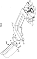
- la figure 2 est une vue partielle éclatée et en perspective illustrant le joint selon l'invention en phase de montage et monté sur une pièce formant également joint bordant une échancrure de passage d'une poignée d'un panier équipant l'appareil de cuisson.
- Figure 1 is a partial schematic representation in vertical section of a cooking appliance according to the invention comprising a seal interposed between the cover and the tank;
- Figure 2 is a partial exploded and perspective view illustrating the seal according to the invention in the assembly phase and mounted on a part also forming a seal bordering a notch for the passage of a handle of a basket fitted to the cooking appliance.
L'appareil représenté à la figure 1 illustre de façon schématique une friteuse comprenant un boîtier 1 renfermant une cuve 2 chauffée par un moyen de chauffage 3 tel qu'une résistance blindée et comportant un panier 4 apte à reposer sur le bord supérieur 5 de la cuve et équipé d'une poignée 6 saillante vers l'extérieur, ainsi qu'un couvercle 7 monté articulé sur le bord supérieur 8 du boîtier 1 au moyen d'une charnière non représentée et susceptible d'occuper une position de fermeture de la cuve 2 (figure 1) lors notamment d'une préparation de friture. Dans l'exemple schématisé, la cuve et le couvercle présentent un contour circulaire, mais il pourrait bien entendu être rectangulaire.The apparatus shown in Figure 1 schematically illustrates a fryer comprising a
Le couvercle 7 comporte un bord descendant 9 et un contre-couvercle 10 fixé par exemple par des vis 11 à la paroi interne 12 du couvercle 7. Comme on le voit mieux sur la partie gauche de la figure 1, le couvercle est équipé d'un joint d'étanchéité 13 comportant une partie tubulaire 14 qui est destinée à venir reposer, lorsque le couvercle est en position de fermeture, sur le bord supérieur 5 de la cuve 2 ou, en présence du panier 4, sur le bord supérieur de ce panier, et qui est relié à une partie 16 formant pied fixée entre le bord périphérique 17 du contre-couvercle 10 et la paroi interne 12 du couvercle 7.The
En outre, le couvercle 7 contient une cartouche filtrante 18 interposée dans un compartiment 19 ménagé entre le contre-couvercle 10 et la paroi interne 12.In addition, the
Dans une réalisation préférentielle de l'appareil de cuisson, le boîtier 1 et le couvercle 7 sont réalisés en une matière plastique susceptible de se dégrader à une température élevée telle que, par exemple, un polypropylène.In a preferred embodiment of the cooking appliance, the
Selon l'invention, le joint 13 comporte en outre une lèvre externe 20 agencée entre la partie tubulaire 14 et le bord descendant 9 du couvercle 7 et s'étendant vers le bas, au-delà du plan P contenant la surface inférieure de la partie tubulaire 14, en direction dudit bord descendant 9. En outre, l'extrémité libre 21 de la lèvre 20 vient au contact de la face de la paroi interne 12 du bord descendant 9 du couvercle 7.According to the invention, the
Comme représenté sur les figures, le joint 13 est un profilé extrudé réalisé en continu et susceptible d'être tronçonné dans la longueur pour s'adapter aux différentes périphéries des cuves de cuisson fabriquées. Dans un but d'optimisation de la fabrication du profilé, la lèvre 20 est implantée sur la périphérie externe de la partie tubulaire 14.As shown in the figures, the
Pour des raisons thermiques, le joint 13 est réalisé en un silicone haute température.For thermal reasons, the
Ainsi, grâce à la réalisation particulière du joint 13 et notamment de la lèvre 20, on obtient, d'une part, une bonne étanchéité entre la paroi interne 12 du couvercle 7 et le contre-couvercle 10 empêchant donc des entrées de vapeur dans l'espace E et partant la formation de gouttelettes de condensation qui peuvent se produire au contact de la paroi froide 12 du couvercle, ainsi que des fuites de vapeur non filtrées par la cartouche 18, et d'autre part, en cas de mauvaise position du couvercle 7 par rapport à la cuve 2, on évite un contact direct dangereux du bord 5 contre le bord descendant 9 et donc la création d'un point chaud susceptible, dans le cas d'un couvercle métallique, de provoquer des brûlures à l'usager, et dans le cas d'un couvercle en polypropylène, de faire fondre la région mitoyenne correspondante du couvercle 7. Le bord supérieur 5 de la cuve peut avoir une forme de crochet comme illustré ou une forme plate identique à celle du panier 4.Thus, thanks to the particular embodiment of the
Dans l'exemple de réalisation de l'appareil de cuisson représenté à la figure 1, la poignée 6 fait saillie vers l'extérieur au travers d'une échancrure de passage 22 pratiquée dans le bord périphérique descendant 9 du couvercle 7. Du fait de cette échancrure, le joint 13 ne peut plus s'étendre sur toute la périphérie du bord 5 de la cuve 2 et l'invention prévoit donc de pallier à cet inconvénient, d'une part, en réalisant le joint 13 selon un tronçon dont les extrémités 24 et 25 (figure 2) s'étendent jusqu'aux bords latéraux de l'échancrure 22 et, d'autre part, en équipant le bord de ladite échancrure d'une pièce moulée 26 formant joint et réalisée en silicone haute température. Cette pièce moulée 26 épouse le bord de l'échancrure et, comme figure 2, présente la forme d'un U dont les branches latérales 28 comportent des pattes 30 destinées à la fixation des extrémités 24 et 25 du joint 13. Cette fixation est de préférence obtenue par collage.In the embodiment of the cooking appliance shown in FIG. 1, the handle 6 projects outwardly through a
Ainsi, le joint profilé 13 s'étend pratiquement sur toute la périphérie du bord 5 de la cuve 2 avec la lèvre correctement appliquée, c'est-à-dire sans frisure, contre le bord descendant 9, et la pièce moulée 26 forme un joint épousant parfaitement le contour anguleux de l'échancrure sans également former de pli et peut ainsi par sa face inférieure 32 venir s'appliquer correctement sur un contre-joint 34 porté par l'embase de la poignée 6 constituant donc une étanchéité parfaite à ce niveau.Thus, the
Claims (10)
- Electric cooking appliance comprising a casing (1) enclosing a container (2) heated by a heating means (3) and equipped with a lid (7) pivotally mounted on the top edge (8) of the casing and able to occupy a position of closure of the container, the said lid having a falling edge (9) and a counter-lid (10) fixed to the internal wall (12) of the lid (7), and a sealing joint (13) having a tubular part (14) designed to come to rest on the top edge (5) of the container when the lid is in the closed position, characterised in that the joint (13) is connected to a part (16) forming a foot fixed between the peripheral edge (17) of the counter-lid (10) and the internal wall (12) of the lid, and has an external lip (20) arranged between the tubular part (14) and the falling edge (9) of the lid (7), and extending downwards, beyond the plane P containing the bottom surface of the tubular part (14), in the direction of the said falling edge (9).
- Electrical cooking appliance according to Claim 1,
characterised in that the joint (13) is an extruded profiled element. - Electrical cooking appliance according to Claim 1 or 2,
characterised in that the lip (20) is located on the external periphery of the tubular part (14). - Electrical cooking appliance according to any one of the preceding claims,
characterised in that the free end (21) of the lip (20) comes into contact with the internal face (12) of the falling edge (9) of the lid (7). - Electrical cooking appliance according to Claims 2 and Claims 3 or 4, in which the container (2) has a basket (4) equipped with a projecting handle (6), and the lid (7) has on its periphery an indentation (22) for the passage of the handle,
characterised in that the indentation (22) is equipped with a moulded part (26) forming a joint following the shape of the cut-out edge of the said indentation and the profiled element (13) is formed by a section whose ends (24, 25) are fixed to the said moulded part (26). - Electrical cooking appliance according to Claim 5,
characterised in that the part (26) forming a joint has lugs (30) and the ends of the joint (13) are fixed respectively to the said lugs by bonding. - Electrical cooking appliance according to Claim 6,
characterised in that the part (26) forming a joint is a part moulded from high-temperature silicone. - Electrical cooking appliance according to any one of the preceding claims,
characterised in that the lid (7) is produced from a plastic liable to degrade at a high temperature. - Electrical cooking appliance according to any one of the preceding claims,
characterised in that it forms a deep fryer. - Electrical cooking appliance according to Claim 9,
characterised in that the lid (7) is equipped with an anti-odour filter (18) arranged between the counter-lid (10) and the internal wall (12) of the lid (7).
Applications Claiming Priority (2)
| Application Number | Priority Date | Filing Date | Title |
|---|---|---|---|
| FR9501465A FR2730152B1 (en) | 1995-02-08 | 1995-02-08 | ELECTRIC COOKING APPLIANCE |
| FR9501465 | 1995-02-08 |
Publications (2)
| Publication Number | Publication Date |
|---|---|
| EP0726055A1 EP0726055A1 (en) | 1996-08-14 |
| EP0726055B1 true EP0726055B1 (en) | 1997-10-29 |
Family
ID=9475959
Family Applications (1)
| Application Number | Title | Priority Date | Filing Date |
|---|---|---|---|
| EP96400167A Expired - Lifetime EP0726055B1 (en) | 1995-02-08 | 1996-01-24 | Electric cooking apparatus |
Country Status (4)
| Country | Link |
|---|---|
| EP (1) | EP0726055B1 (en) |
| DE (1) | DE69600085T2 (en) |
| ES (1) | ES2108589T3 (en) |
| FR (1) | FR2730152B1 (en) |
Families Citing this family (1)
| Publication number | Priority date | Publication date | Assignee | Title |
|---|---|---|---|---|
| FR2750312B1 (en) * | 1996-06-27 | 1998-12-24 | Moulinex Sa | COOKING APPLIANCE |
Family Cites Families (5)
| Publication number | Priority date | Publication date | Assignee | Title |
|---|---|---|---|---|
| FR1517736A (en) * | 1966-07-21 | 1968-03-22 | Seb Sa | Domestic fryer |
| BE791213A (en) * | 1972-04-17 | 1973-03-01 | Matsushita Electric Ind Co Ltd | DEEP FRYER |
| FR2239224B1 (en) * | 1973-08-02 | 1976-06-18 | Seb Ste Emboutissage Bourgogne | |
| DE3103450C2 (en) * | 1981-02-02 | 1983-01-13 | Melitta-Werke Bentz & Sohn, 4950 Minden | Fryer with a viewing window lid |
| GB9217090D0 (en) * | 1992-08-12 | 1992-09-23 | Morphy Ltd Richards | Fryers |
-
1995
- 1995-02-08 FR FR9501465A patent/FR2730152B1/en not_active Expired - Fee Related
-
1996
- 1996-01-24 DE DE69600085T patent/DE69600085T2/en not_active Expired - Fee Related
- 1996-01-24 EP EP96400167A patent/EP0726055B1/en not_active Expired - Lifetime
- 1996-01-24 ES ES96400167T patent/ES2108589T3/en not_active Expired - Lifetime
Also Published As
| Publication number | Publication date |
|---|---|
| ES2108589T3 (en) | 1997-12-16 |
| EP0726055A1 (en) | 1996-08-14 |
| DE69600085T2 (en) | 1998-03-05 |
| DE69600085D1 (en) | 1997-12-04 |
| FR2730152B1 (en) | 1998-06-19 |
| FR2730152A1 (en) | 1996-08-09 |
Similar Documents
| Publication | Publication Date | Title |
|---|---|---|
| EP0807394B1 (en) | Electrical kettle with heating metallic plate | |
| FR3070847B1 (en) | FOOD PREPARATION AND / OR COOKING ASSEMBLY FOR HOUSEHOLD KITCHEN ROBOT | |
| EP0777433B1 (en) | Heating device for foodstuffs, particularly for frying, with an outer bowl | |
| WO2010136711A2 (en) | Electric domestic appliance for food preparation, comprising a base for receiving a working vessel including a heating plate | |
| EP3184007B1 (en) | Reinforced pressure cooker | |
| FR2744001A1 (en) | ELECTRIC KETTLE WITH HEATING BOTTOM | |
| EP0726055B1 (en) | Electric cooking apparatus | |
| EP1117318B1 (en) | Electrical appliance for heating liquids, comprising a heating base and glass walls | |
| EP1154714B1 (en) | Electric kettle with metal heating plate | |
| EP1941819B1 (en) | Cooking appliance | |
| EP0460618B1 (en) | Electrical boiler | |
| EP1557120B1 (en) | Hood of an electrical waffle cooker | |
| EP1032296B1 (en) | Pressure cooker comprising means supporting a cooking basket in high position | |
| EP1795096B1 (en) | Cooking device | |
| FR2629587A1 (en) | PERFECTED TYPE TRANSDUCER | |
| FR2614400A1 (en) | Autonomous radiant heat cooker - uses gas canister in base to supply vertically mounted central burner enclosed by screen-producing radiant heat | |
| FR2829907A1 (en) | Home yoghurt maker has cover with raised edges shaped to receive pot lids | |
| FR3070587A1 (en) | KITCHEN TOOL | |
| EP2000066B1 (en) | Medium for cooking a small amount of food | |
| FR2713465A1 (en) | NTC sensor on flexible support for meat grill. | |
| FR2728450A3 (en) | APPARATUS FOR HEATING LIQUIDS | |
| FR2645515A1 (en) | Leaktight cover, in particular for run off container of road tanker | |
| FR2711500A1 (en) | Electrically-heated deep fryer | |
| CH495736A (en) | Electric food grill |
Legal Events
| Date | Code | Title | Description |
|---|---|---|---|
| PUAI | Public reference made under article 153(3) epc to a published international application that has entered the european phase |
Free format text: ORIGINAL CODE: 0009012 |
|
| AK | Designated contracting states |
Kind code of ref document: A1 Designated state(s): BE DE ES GB IT NL |
|
| GRAG | Despatch of communication of intention to grant |
Free format text: ORIGINAL CODE: EPIDOS AGRA |
|
| 17P | Request for examination filed |
Effective date: 19970129 |
|
| GRAH | Despatch of communication of intention to grant a patent |
Free format text: ORIGINAL CODE: EPIDOS IGRA |
|
| 17Q | First examination report despatched |
Effective date: 19970324 |
|
| GRAH | Despatch of communication of intention to grant a patent |
Free format text: ORIGINAL CODE: EPIDOS IGRA |
|
| GRAA | (expected) grant |
Free format text: ORIGINAL CODE: 0009210 |
|
| AK | Designated contracting states |
Kind code of ref document: B1 Designated state(s): BE DE ES GB IT NL |
|
| GBT | Gb: translation of ep patent filed (gb section 77(6)(a)/1977) |
Effective date: 19971031 |
|
| REF | Corresponds to: |
Ref document number: 69600085 Country of ref document: DE Date of ref document: 19971204 |
|
| REG | Reference to a national code |
Ref country code: ES Ref legal event code: FG2A Ref document number: 2108589 Country of ref document: ES Kind code of ref document: T3 |
|
| ITF | It: translation for a ep patent filed |
Owner name: FUMERO BREVETTI S.N.C. |
|
| PLBE | No opposition filed within time limit |
Free format text: ORIGINAL CODE: 0009261 |
|
| STAA | Information on the status of an ep patent application or granted ep patent |
Free format text: STATUS: NO OPPOSITION FILED WITHIN TIME LIMIT |
|
| 26N | No opposition filed | ||
| REG | Reference to a national code |
Ref country code: GB Ref legal event code: IF02 |
|
| NLS | Nl: assignments of ep-patents |
Owner name: SEB S.A. |
|
| REG | Reference to a national code |
Ref country code: ES Ref legal event code: PC2A |
|
| REG | Reference to a national code |
Ref country code: GB Ref legal event code: 732E |
|
| PG25 | Lapsed in a contracting state [announced via postgrant information from national office to epo] |
Ref country code: IT Free format text: LAPSE BECAUSE OF NON-PAYMENT OF DUE FEES;WARNING: LAPSES OF ITALIAN PATENTS WITH EFFECTIVE DATE BEFORE 2007 MAY HAVE OCCURRED AT ANY TIME BEFORE 2007. THE CORRECT EFFECTIVE DATE MAY BE DIFFERENT FROM THE ONE RECORDED. Effective date: 20050124 |
|
| PGFP | Annual fee paid to national office [announced via postgrant information from national office to epo] |
Ref country code: NL Payment date: 20080131 Year of fee payment: 13 |
|
| PGFP | Annual fee paid to national office [announced via postgrant information from national office to epo] |
Ref country code: BE Payment date: 20080312 Year of fee payment: 13 |
|
| PGFP | Annual fee paid to national office [announced via postgrant information from national office to epo] |
Ref country code: ES Payment date: 20090105 Year of fee payment: 14 |
|
| PGFP | Annual fee paid to national office [announced via postgrant information from national office to epo] |
Ref country code: DE Payment date: 20090212 Year of fee payment: 14 |
|
| PGFP | Annual fee paid to national office [announced via postgrant information from national office to epo] |
Ref country code: GB Payment date: 20081201 Year of fee payment: 14 |
|
| NLV4 | Nl: lapsed or anulled due to non-payment of the annual fee |
Effective date: 20090801 |
|
| PG25 | Lapsed in a contracting state [announced via postgrant information from national office to epo] |
Ref country code: NL Free format text: LAPSE BECAUSE OF NON-PAYMENT OF DUE FEES Effective date: 20090801 |
|
| PG25 | Lapsed in a contracting state [announced via postgrant information from national office to epo] |
Ref country code: BE Free format text: LAPSE BECAUSE OF NON-PAYMENT OF DUE FEES Effective date: 20090131 |
|
| GBPC | Gb: european patent ceased through non-payment of renewal fee |
Effective date: 20100124 |
|
| PG25 | Lapsed in a contracting state [announced via postgrant information from national office to epo] |
Ref country code: DE Free format text: LAPSE BECAUSE OF NON-PAYMENT OF DUE FEES Effective date: 20100803 |
|
| PG25 | Lapsed in a contracting state [announced via postgrant information from national office to epo] |
Ref country code: GB Free format text: LAPSE BECAUSE OF NON-PAYMENT OF DUE FEES Effective date: 20100124 |
|
| REG | Reference to a national code |
Ref country code: ES Ref legal event code: FD2A Effective date: 20110224 |
|
| PG25 | Lapsed in a contracting state [announced via postgrant information from national office to epo] |
Ref country code: ES Free format text: LAPSE BECAUSE OF NON-PAYMENT OF DUE FEES Effective date: 20110223 |
|
| PG25 | Lapsed in a contracting state [announced via postgrant information from national office to epo] |
Ref country code: ES Free format text: LAPSE BECAUSE OF NON-PAYMENT OF DUE FEES Effective date: 20100125 |