EP2805649B1 - Boiler comprising a sealed control module - Google Patents
Boiler comprising a sealed control module Download PDFInfo
- Publication number
- EP2805649B1 EP2805649B1 EP14167258.4A EP14167258A EP2805649B1 EP 2805649 B1 EP2805649 B1 EP 2805649B1 EP 14167258 A EP14167258 A EP 14167258A EP 2805649 B1 EP2805649 B1 EP 2805649B1
- Authority
- EP
- European Patent Office
- Prior art keywords
- kettle
- control device
- cable
- seal
- wall
- Prior art date
- Legal status (The legal status is an assumption and is not a legal conclusion. Google has not performed a legal analysis and makes no representation as to the accuracy of the status listed.)
- Active
Links
Images

Classifications
-
- A—HUMAN NECESSITIES
- A47—FURNITURE; DOMESTIC ARTICLES OR APPLIANCES; COFFEE MILLS; SPICE MILLS; SUCTION CLEANERS IN GENERAL
- A47J—KITCHEN EQUIPMENT; COFFEE MILLS; SPICE MILLS; APPARATUS FOR MAKING BEVERAGES
- A47J27/00—Cooking-vessels
- A47J27/21—Water-boiling vessels, e.g. kettles
- A47J27/21008—Water-boiling vessels, e.g. kettles electrically heated
-
- A—HUMAN NECESSITIES
- A47—FURNITURE; DOMESTIC ARTICLES OR APPLIANCES; COFFEE MILLS; SPICE MILLS; SUCTION CLEANERS IN GENERAL
- A47J—KITCHEN EQUIPMENT; COFFEE MILLS; SPICE MILLS; APPARATUS FOR MAKING BEVERAGES
- A47J27/00—Cooking-vessels
- A47J27/21—Water-boiling vessels, e.g. kettles
- A47J27/21166—Constructional details or accessories
Definitions
- the present invention relates to a kettle and aims to improve the sealing of the kettle so that it can be washed completely after each use without impairing the proper functioning of the device during frequent use.
- the kettle according to WO 2009/109762 A1 comprises a body, a heating plate, a lower housing in which is housed an internal control device, sealing means being implemented between the body, the heating plate and the lower housing.
- This kettle has a control switch arranged in a sealed manner on the lower housing.
- a control switch located in a lower part of the kettle is not very accessible to the user.
- the switch has a button operated by the user by a horizontal support. Thus, such a kettle is not ergonomic.
- the Chinese patent application published under the number CN 201213711 discloses a kettle having a handle on which is arranged an external control device. This arrangement is more ergonomic. However, the assembly of such a control device in the handle is long and complicated. In addition, such a control device is not waterproof.
- the present invention aims to overcome these disadvantages by implementing a kettle which has a reliable sealed control device which is ergonomic and which is simple and economical design to implement.
- the invention relates to a kettle according to claim 1, which comprises a body, a heating plate and a lower housing in which is housed an internal control device of the heating plate. of the sealing means are implemented between the body, the plate and the lower housing.
- the kettle includes an external controller connected to the internal controller and configured to manually operate the internal controller.
- the external control device forms a sealed self-contained module.
- external control device By an external control device connected to the internal control device, it is understood that external control device interacts with the internal control device by any type of connection, in particular a cable, a magnetic link or a wireless connection by electromagnetic waves of the type Bluetooth, infrared or wifi.
- the kettle according to the invention also provides a seal from the outside, which allows to wash and rinse with water the outside of this kettle, without risk of water infiltration into the external control device which could propagate along the cable disposed inside the kettle and connected to the internal control device.
- the body comprises a handle.
- the external control device is arranged on the handle. This ergonomic design makes it easy to operate the kettle.
- the external control device is connected by a cable to the internal control device.
- sealing means are arranged between the cable and the lower housing. This enhances the watertightness of the kettle by preventing any risk of water infiltration into the lower case due to the cable connection with the internal control device disposed in the lower case.
- the external control device is connected to the internal control device by a magnetic link or a wireless connection by electromagnetic waves of the Bluetooth, infrared or wifi type.
- This arrangement makes it possible to obtain an autonomous module without physical elements of the wire type for connection to the control device.
- the tightness of the module is easy to achieve.
- the sealing means are formed by a stuffing box arranged on the lower housing.
- the sealing means are formed by a wall passage overmoulded on the cable.
- sealing means are arranged between the cable and the external control device.
- the sealing member is a gland.
- the sealing member is a cast resin surrounding the cable.
- Such a sealing member formed by a cast resin, initially in the liquid state for its introduction and which hardens to ensure good bonding between the coated parts, allows the kettle to be passed under water without risk of leaks, especially around the cable.
- the handle comprises a first portion 3a internal forming a recess in which is arranged the external control device.
- the handle has a second dressing part which caps said external control device on the handle.
- the cable extends inside the handle to the lower housing. This avoids providing an additional housing on the body of the kettle to allow the passage of the cable to the lower housing.
- the lower housing comprises a peripheral inner wall, preferably of circular shape, which extends upwards.
- the body has a lower part.
- the heating plate includes a lower face and a peripheral rim.
- An outer seal is arranged between the peripheral rim and the portion lower.
- an internal seal is arranged between the inner wall and the lower face of the heating plate to prevent water penetration into the housing, in particular water resulting from a leak due to a defect. sealing of the outer seal.
- the lower part of the body comprises a peripheral outer wall configured to receive at least an upper portion of the inner wall while maintaining a spacing between these two inner and outer walls, said spacing communicating to the outside of the kettle.
- the heating plate comprises a peripheral rim provided with an outer edge curved downwards and configured to be positioned between the inner wall and the outer wall by maintaining a spacing, a part, between the inner wall and the outer edge and, on the other hand, between the outer edge and the outer wall.
- the inner seal is arranged between the inner wall and the outer edge and the outer seal is arranged between the outer edge and the outer wall.
- the outer seal prevents water from escaping between the outer wall of the body and the outer edge of the rim of the hotplate.
- the internal seal prevents water from entering between the inner wall of the lower housing and the outer edge of the rim of the hotplate during cleaning of the kettle with water.
- the outer seal is more stressed than the inner seal when wiping the inside of the body of the kettle. This can cause damage to the outer seal more quickly than the inner seal.
- the water then passes between the outer wall of the body and the outer edge of the rim of the hotplate and discharges directly to the outside of the kettle. On the one hand, this avoids the risk of water penetration into the lower case in case the internal seal is also defective; on the other hand, it allows detect leakage of the external seal and replace it.
- the peripheral rim is also provided with an inner edge curved downwards and configured to allow the housing of the upper part of the inner wall between the inner edge and the outer edge.
- the inner seal is configured to also provide a seal between the inner edge and the upper portion of the inner wall. This enhances the seal between the hotplate and the lower housing, as well as maintaining the assembled hotplate on the lower housing.
- the outer face of the outer branch comprises at least one lip.
- the outer edge of the flange comprises an inner face provided with ridges. This strengthens the assembly and sealing between the hotplate and the lower housing.
- the outer edge of the peripheral rim comprises at its lower end an outer shoulder and the outer wall comprises an inner shoulder.
- the outer seal is positioned between the inner shoulder and the shoulder external. This allows sealing between the body and the heating plate by ensuring a stop of the body position relative to the hotplate.
- the inner wall of the lower housing comprises a lower portion, a peripheral outer shoulder being arranged between said lower portion and the upper portion of said inner wall.
- the inner shoulder of the outer wall of the body and the outer shoulder of the outer edge are configured to maintain a spacing between the peripheral lower end of the body and the outer shoulder of the lower housing during assembly, which allows the evacuation of water in case of failure of the outer seal.
- fixing means are arranged between the lower end of the outer wall of the body and the outer shoulder of the lower housing. This keeps the body, the hot plate and the lower housing together.
- the kettle object of the invention comprises a remote power supply base provided with a male connector.
- the lower housing comprises a bottom provided with a female connector configured to receive the male connector, said female connector being configured to seal the lower housing.
- the male connector and the female connector are circular. This provides 360 ° rotation of the body on the base to facilitate handling and allow positioning or removal of the kettle body in any position relative to the base.
- the kettle 1 comprises a body 2 which is advantageously plastic.
- a body 2 of plastic ensures a very low heat conduction to prevent the user burns himself when handling the kettle containing boiling water.
- a handle 3 fixed to the body 2.
- the body 2 and the handle 3 are made in one piece by molding.
- the body 2 comprises a peripheral outer wall 4, preferably of circular shape, which extends downwards.
- the upper part 4a of the outer wall 4 comprises a spout 5 for pouring boiling water when the body 2 is inclined.
- This upper part 4a comprises an opening 6 which receives a closure cap 7.
- This lid 7 comprises an opening / closing system 8 allowing the lid to be snapped onto the upper part 4a of the body when it is put in place at the opening 6.
- This opening / closing system 8 comprises lugs 9a, 9b retractable when actuating an activation button 10, these lugs 9a, 9b being positioned under the periphery 11 of the opening 6.
- the kettle 1 comprises a lower housing 12 also in a plastic material ensuring low conduction thermal.
- This lower housing 12 comprises a peripheral inner wall 13 and a bottom 14.
- the inner wall 13 extends upwards and has a shape similar to the outer wall 4 of the body 2, in this case a circular shape.
- the diameter of the inner wall 13 is smaller than that of the lower part 4b of the outer wall 4, which allows the introduction of the upper part 13a inner wall 13 inside the lower part 4b of the outer wall 4 , maintaining a spacing 15 over the entire periphery between said inner and outer walls 13 and 4.
- the kettle 1 also comprises a heating plate 16 which has a very good thermal conduction and constitutes the bottom of a chamber 17 for containing water to boil it.
- the contour 17a of this chamber 17 is constituted by the upper part 4a of the outer wall 4 of the body 2.
- the heating plate 16 comprises a peripheral rim 18 of similar shape to the inner walls 13 and outer 4, in this case of circular shape .
- This flange 18 comprises an inner edge 19 and an outer edge 20, circular in shape, both of which are curved downwards and extend over a length that makes it possible to receive the upper part 13a of the inner wall 13 between said edges. internal 19 and outer 20, as illustrated in detail on the figure 2 .
- the diameter of the inner edge 19 is sized to maintain a second spacing 21 between said inner edge 19 and the upper portion 13a of the inner wall 13, as illustrated in FIG. figure 2 .
- the diameter and the thickness of the outer edge 20 are sized to maintain, on the one hand, a third spacing 22 between the upper portion 13a of the inner wall 13 and the outer edge 20 and, on the other hand, a fourth gap 23 between the outer edge 20 and the lower part 4b of the outer wall 4, as illustrated in FIG. figure 2 .
- an internal seal 24 is arranged between the flange 18 of the heating plate 16 and the upper part 13a of the inner wall 13.
- This internal seal 24 has an annular shape and comprises an inner branch 25, a branch external 26 and a junction 27 between the inner 25 and outer 26 branches.
- the diameter of the inner face 25a of the inner branch 25 is sized to allow its tight assembly around of the outer face 19a of the inner edge 19 of the flange 18, as illustrated in FIG. figure 2 .
- the thickness of the inner branch 25 makes it possible to maintain a fifth spacing 28 between the outer face 25b of the inner branch 25 and the inner face 29a of the upper part 13a of the inner wall 13.
- the diameter of the inner face 26a of the outer branch 26 is dimensioned to allow tight fitting of the outer branch 26 on the outer face 29b of the upper portion 13a of the inner wall 13.
- the outer face 26b of the outer branch 26 comprises contiguous lips 30a, 30b which provide a tight fit on the inner face 20a of the outer edge 20 of the flange 18.
- This inner face 20a of the outer edge 20 comprises ridges 31a, 31b
- the lower face 27a of the junction 27 bears against the upper end 32 of the upper part 13a of the inner wall 13.
- the upper face 27b of the junction bears against the bottom 33 of the flange 18.
- the portion of the lower face of the heating plate 16 located at the flange 18 is kept nested and assembled, in a sealed manner, on the upper part 13a of the inner wall 13 of the lower housing 12.
- the outer edge 20 of the flange 18 comprises at its lower end an outer shoulder 34 which extends radially to the periphery of the heating plate 16.
- the lower portion 4b of the outer wall 4 of the body 2 comprises an internal shoulder 35 arranged in such a way that it is disposed above this outer shoulder 34.
- an outer seal 36 has the shape of a torus and has an internal face 36a whose diameter ensures a tight fitting around the outer face 20b of the outer edge 20, as illustrated in FIG. figure 2 .
- this seal 36 comprises an outer face 36b whose diameter provides a tight fit of the inner face 37 of the lower portion 4b of the outer wall 4, located below the inner shoulder 35, as illustrated in FIG. figure 2 .
- this external seal 36 ensures an indirect stop between the outer shoulder 34 of the outer edge 20 and the internal shoulder 35 of the wall 4, which ensures a stop in position of the body 2 relative to the heating plate 16, and thus a stop in position of the body relative to the lower housing 12.
- an outer circumferential shoulder 38 is arranged between the upper part 13a and a lower part 13b of the inner wall 13 of the lower casing 12.
- the distance separating this outer shoulder 38 from the upper end 32 of the inner wall 13 and the distance between the lower end 39 of the outer wall 4 of the body 2 and the inner shoulder 35 on said outer wall 4, are dimensioned so that when the abutment of the inner shoulder 35 with respect to the shoulder external 34 on the rim 18 of the heating plate 16, through the outer seal 36, a sixth gap 40 is preserved between the lower end 39 of the body 2 and the outer shoulder 38 of the lower housing 12.
- This sixth spacing 40 is disposed in the continuity of the first spacing 15 between the inner wall 13 and the outer wall 4.
- the lower end 39 of the outer wall 4 comprises holes 41 uniformly distributed around the body 2, which allow the passage of fastening screws (not shown).
- the lower part 13a of the inner wall 13 comprises, at the level of the outer shoulder 38, threads (not shown) uniformly distributed around the lower casing 12, in correspondence with the holes 41. These threads allow the fixing screws to be screwed in. for the assembled retention of the body 2 on the lower housing 12. This attachment also ensures the connection between the heating plate 16 and the upper portion 13a of the inner wall 13 of the lower housing 12 and between the heating plate 16 and the lower part 4b of the outer wall 4 of the body 2.
- said lower housing 12 defines an inner chamber 42 which allows in particular the housing of a resistor heater 43 fixed below the heating plate 16, an electromechanical internal control device 44 and a temperature sensor 45.
- the lower housing 12 comprises a female electrical connector 46, arranged in a sealed manner in the bottom 14 of the lower housing 12
- This electrical connector 46 is connected to the electromechanical internal control device 44 and allows its electrical connection to a base or base 63 which comprises a male connector 64 complementary to the electrical connector 46 female.
- This base is configured to be electrically connected to an external power source through a power outlet.
- the electrical connector 46 is circular, which is also the case of the electrical connector on the base. This allows a connection of the body 2 to the power supply base in any 360 ° orientation.
- Such a base is not illustrated but is known to those skilled in the art.
- the handle 3 of the kettle 1 consists of a first portion 3a completely integrated to the body 2, and a second portion 3b removable.
- the second part 3b comprises fixing tabs 47a, 47b which snap inside the first part 3a of this handle 3.
- the first part 3a of the handle 3 comprises an internal recess 48, illustrated in FIG. figure 3 , which allows the housing and the passage of a cable 65 (shown in FIGS. Figures 3 and 4 ) for its connection to the lower housing 12.
- the inner wall 13 comprises a passage hole (not shown) of the cable 65 and a gland is mounted at said passage hole to allow the introduction of the cable 65 of sealed manner inside the inner chamber 42.
- an external control device 49 is arranged in the upper part of the handle 3 and allows the activation of the electromechanical internal control device 44.
- This external control device 49 comprises a lower support 50 which is housed in the internal recess 48 of the first part 3a of the handle 3 and fixed inside this recess 48 by means of fixing screws 5 illustrated in FIG. figure 3 .
- the external control device 49 also comprises a printed circuit board 52 which incorporates an on / off switch 53 of the ON / OFF switch type.
- This card printed circuit 52 is fixed on the upper face 50a of the lower support 50 by means of fixing screws 54, as illustrated in FIG. figure 4 .
- the upper end of the cable 65 passes through the lower support 50 and is connected to the printed circuit board 52.
- the external control device 49 comprises a seal 56 of elastomeric material which comprises a central portion 56a provided with a flexible button 57, this central portion 56a being configured to cover the components on the printed circuit board 52 and the switch 53 by marrying their shape.
- the flexibility of the flexible button 57 allows its deformation when the user exerts a pressure on it and thus the activation of the switch 53.
- the seal 56 also comprises a peripheral contour 56b which is flat and which rests on the contour 52a of the printed circuit board 52.
- the external control device 49 also comprises a clamping piece 58 which comprises in its central part an opening 59 which is configured to allow the passage of the central portion 56a of the seal 56.
- clamping piece 58 comprises a peripheral and flat contour 58a which bears on top of the contour 56b of the seal 56 and makes it possible to sandwich said contour 56b of the elastomer seal 56 between the contour 52a of the printed circuit board 52 and the contour 58a of the clamping piece 58.
- the contour 52a of the printed circuit board 52 rests on the upper face 50a of the support piece 50, which implies that the contour 56b of the seal 56 is supported indirectly on said upper face 50a.
- the second portion 3b of the handle 3 comprises an opening 61 which allows the passage of the flexible button 57 and the switch 53 during its assembly with the first portion 3a of the handle.
- the contour 62 of this opening bears on the central portion 56a of the seal 56, around the flexible button 57, which ensures also a seal between the external control device 49 and the handle 3.
- the circuit board 52 is capped by the seal 56.
- the printed circuit board 52 and the seal are arranged between the locking piece 58 and the support piece 50.
- the locking piece 58 and the support piece 50 are assembled by clipping.
- the circuit board 52 has a rear face 70 which is bordered by the seal.
- a resin 155 is gravity-cast in a cavity formed by the rear face 70, the seal 56 and the locking piece 58.
- the resin 155 surrounds the cable 65 and covers the rear face 70, the seal 56 and a peripheral edge of the locking piece.
- the resin 155 is initially in the liquid state so that it can be cast into the cavity and then hardens to make a tight connection between the coated parts, in particular the tightness of the passage of the cable 65.
- the cast resin 155 will preferably be a polyurethane resin.
Description
La présente invention concerne une bouilloire et vise à améliorer l'étanchéité de la bouilloire afin de pouvoir la laver complètement après chaque utilisation sans nuire au bon fonctionnement de l'appareil lors d'un usage fréquent.The present invention relates to a kettle and aims to improve the sealing of the kettle so that it can be washed completely after each use without impairing the proper functioning of the device during frequent use.
Diverses conceptions de bouilloires étanches sont connues de l'homme du métier, parmi lesquelles, par exemple, celle décrite dans la demande internationale de brevet publiée sous le numéro
La demande de brevet chinois publiée sous le numéro
On connait également du document
La présente invention vise à pallier ces inconvénients en mettant en oeuvre une bouilloire qui présente un dispositif de commande étanche fiable qui soit ergonomique et qui soit de conception simple et économique à mettre en oeuvre.The present invention aims to overcome these disadvantages by implementing a kettle which has a reliable sealed control device which is ergonomic and which is simple and economical design to implement.
A cet effet, l'invention concerne une bouilloire selon la revendication 1, qui comprend un corps, une plaque chauffante et un boîtier inférieur dans lequel est logé un dispositif de commande interne de la plaque chauffante. Des moyens d'étanchéité sont mis en oeuvre entre le corps, la plaque et le boîtier inférieur. En outre, la bouilloire comprend un dispositif de commande externe relié au dispositif de commande interne et configuré pour actionner manuellement ledit dispositif de commande interne. Selon l'invention, le dispositif de commande externe forme un module autonome étanche. Par module autonome, on comprend que le dispositif de commande est assemblé pour former un sous ensemble qui sera ensuite rapporté sur la bouilloire. Ce module étanche peut être testé avant son montage sur la bouilloire. On obtient ainsi une bouilloire comportant un dispositif de commande de conception simple et économique à mettre en oeuvre. Un tel dispositif de commande est également très fiable.To this end, the invention relates to a kettle according to
Par un dispositif de commande externe relié au dispositif de commande interne, on comprend que dispositif de commande externe interagit avec le dispositif de commande interne par tous type de liaison, notamment un câble, une liaison magnétique ou une liaison sans fil par ondes électromagnétiques du type Bluetooth, infrarouge ou wifi.By an external control device connected to the internal control device, it is understood that external control device interacts with the internal control device by any type of connection, in particular a cable, a magnetic link or a wireless connection by electromagnetic waves of the type Bluetooth, infrared or wifi.
La bouilloire selon l'invention assure également une étanchéité par l'extérieur, ce qui permet de laver et de rincer à l'eau l'extérieur de cette bouilloire, sans risque d'infiltration d'eau dans le dispositif de commande externe qui pourrait se propager le long du câble disposé à l'intérieur de la bouilloire et raccordé au dispositif de commande interne.The kettle according to the invention also provides a seal from the outside, which allows to wash and rinse with water the outside of this kettle, without risk of water infiltration into the external control device which could propagate along the cable disposed inside the kettle and connected to the internal control device.
Selon une réalisation de la bouilloire objet de l'invention, le corps comprend une poignée. En outre, le dispositif de commande externe est agencé sur la poignée. Cette conception ergonomique facilite l'actionnement de la bouilloire.According to one embodiment of the kettle object of the invention, the body comprises a handle. In addition, the external control device is arranged on the handle. This ergonomic design makes it easy to operate the kettle.
Avantageusement, le dispositif de commande externe est raccordé par un câble au dispositif de commande interne.Advantageously, the external control device is connected by a cable to the internal control device.
Selon une mise en oeuvre de la bouilloire objet de l'invention, des moyens d'étanchéité sont agencés entre le câble et le boîtier inférieur. Cela renforce l'étanchéité de la bouilloire en empêchant tout risque d'une infiltration d'eau dans le boîtier inférieur du fait de la connexion par câble avec le dispositif de commande interne disposé dans le boîtier inférieur.According to one embodiment of the kettle object of the invention, sealing means are arranged between the cable and the lower housing. This enhances the watertightness of the kettle by preventing any risk of water infiltration into the lower case due to the cable connection with the internal control device disposed in the lower case.
Avantageusement, le dispositif de commande externe est relié au dispositif de commande interne par une liaison magnétique ou une liaison sans fil par ondes électromagnétiques du type Bluetooth, infrarouge ou wifi.Advantageously, the external control device is connected to the internal control device by a magnetic link or a wireless connection by electromagnetic waves of the Bluetooth, infrared or wifi type.
Cette disposition permet d'obtenir un module autonome sans éléments physiques du type fils pour la liaison au dispositif de commande. Ainsi, l'étanchéité du module est facile à réaliser.This arrangement makes it possible to obtain an autonomous module without physical elements of the wire type for connection to the control device. Thus, the tightness of the module is easy to achieve.
Selon une mise en oeuvre de la bouilloire, les moyens d'étanchéité sont formés par un presse-étoupe agencé sur le boîtier inférieur.According to one implementation of the kettle, the sealing means are formed by a stuffing box arranged on the lower housing.
Selon une variante de mise en oeuvre de la bouilloire, les moyens d'étanchéité sont formés par un passage de paroi surmoulé sur le câble.According to an alternative embodiment of the kettle, the sealing means are formed by a wall passage overmoulded on the cable.
Avantageusement, des moyens d'étanchéité sont agencés entre le câble et le dispositif de commande externe.Advantageously, sealing means are arranged between the cable and the external control device.
Selon une conception préférentielle, le dispositif de commande externe comprend :
- un support inférieur, le câble passant au travers du support inférieur ;
- une carte circuit imprimé comprenant un interrupteur Marche/Arrêt, la carte circuit imprimé étant positionnée sur le support inférieur ;
- un joint élastomère configuré pour recouvrir la carte circuit imprimé et l'interrupteur Marche/Arrêt, en épousant leur forme et en laissant apparaître un contour périphérique plat qui repose sur le support inférieur;
- une pièce de serrage permettant de serrer en sandwich le contour du joint élastomère entre le support inférieur et la pièce de serrage ;
- un organe d'étanchéité agencé sur le support inférieur et configuré pour permettre le passage étanche du câble, ledit câble étant raccordé à la carte circuit imprimé.
- a lower support, the cable passing through the lower support;
- a printed circuit board comprising an on / off switch, the printed circuit board being positioned on the lower support;
- an elastomeric seal configured to cover the circuit board and the on / off switch, marrying their shape and revealing a flat peripheral contour that rests on the lower support;
- a clamping piece for sandwiching the contour of the elastomeric seal between the lower support and the clamping piece;
- a sealing member arranged on the lower support and configured to allow the sealed passage of the cable, said cable being connected to the printed circuit board.
Selon une mise en oeuvre de la bouilloire, l'organe d'étanchéité est un presse étoupe.According to one implementation of the kettle, the sealing member is a gland.
Selon une variante de mise en oeuvre de la bouilloire, l'organe d'étanchéité est une résine coulée entourant le câble.According to a variant embodiment of the kettle, the sealing member is a cast resin surrounding the cable.
Avantageusement dans cette variante de réalisation, le dispositif de commande externe comprend :
- un support inférieur, le câble passant au travers du support inférieur ;
- une carte circuit imprimé comprenant un interrupteur Marche/Arrêt ;
- un joint élastomère configuré pour recouvrir la carte circuit imprimé et l'interrupteur en épousant leur forme et en laissant apparaître un contour périphérique plat ;
- une pièce de serrage permettant de serrer en sandwich le contour du joint élastomère entre le support inférieur et la pièce de serrage ;
- la résine coulée recouvre une face arrière de la carte circuit imprimé, ladite face arrière étant bordée par le joint élastomère.
- a lower support, the cable passing through the lower support;
- a printed circuit board including an on / off switch;
- an elastomeric seal configured to cover the printed circuit board and the switch by matching their shape and revealing a flat peripheral contour;
- a clamping piece for sandwiching the contour of the elastomeric seal between the lower support and the clamping piece;
- the casting resin covers a rear face of the printed circuit board, said rear face being bordered by the elastomer seal.
Un tel organe d'étanchéité formée par une résine coulée, initialement à l'état liquide pour sa mise en place puis qui durcit pour assurer une bonne liaison entre les pièces recouvertes, permet de passer la bouilloire sous l'eau sans risque de fuites, notamment autour du câble.Such a sealing member formed by a cast resin, initially in the liquid state for its introduction and which hardens to ensure good bonding between the coated parts, allows the kettle to be passed under water without risk of leaks, especially around the cable.
Selon une mise en oeuvre de la bouilloire, la poignée comporte une première partie 3a interne formant un évidement dans lequel est agencé le dispositif de commande externe. En outre, la poignée comporte une seconde partie d'habillage qui coiffe ledit dispositif de commande externe sur la poignée.According to one implementation of the kettle, the handle comprises a
Selon cette réalisation de la bouilloire, le câble s'étend à l'intérieur de la poignée jusqu'au boîtier inférieur. Cela évite de prévoir un logement supplémentaire sur le corps de la bouilloire pour permettre le passage du câble jusqu'au boîtier inférieur.According to this embodiment of the kettle, the cable extends inside the handle to the lower housing. This avoids providing an additional housing on the body of the kettle to allow the passage of the cable to the lower housing.
Selon une conception de la bouilloire objet de l'invention, le boîtier inférieur comprend une paroi interne périphérique, de préférence de forme circulaire, qui s'étend vers le haut. Le corps comporte une partie inférieure. La plaque chauffante comprend une face inférieure et un rebord périphérique. Un joint d'étanchéité externe est agencé entre le rebord périphérique et la partie inférieure. Selon l'invention, un joint d'étanchéité interne est agencé entre la paroi interne et la face inférieure de la plaque chauffante pour empêcher toute pénétration d'eau dans le boitier, notamment de l'eau issue d'une fuite due à un défaut d'étanchéité du joint d'étanchéité externe.According to a design of the kettle object of the invention, the lower housing comprises a peripheral inner wall, preferably of circular shape, which extends upwards. The body has a lower part. The heating plate includes a lower face and a peripheral rim. An outer seal is arranged between the peripheral rim and the portion lower. According to the invention, an internal seal is arranged between the inner wall and the lower face of the heating plate to prevent water penetration into the housing, in particular water resulting from a leak due to a defect. sealing of the outer seal.
Selon une conception de la bouilloire objet de l'invention, la partie inférieure du corps comprend une paroi externe périphérique configurée pour réceptionner au moins une partie supérieure de la paroi interne tout en conservant un espacement entre ces deux parois interne et externe, ledit espacement communiquant vers l'extérieur de la bouilloire.According to a design of the kettle object of the invention, the lower part of the body comprises a peripheral outer wall configured to receive at least an upper portion of the inner wall while maintaining a spacing between these two inner and outer walls, said spacing communicating to the outside of the kettle.
Selon une conception de la bouilloire objet de l'invention, la plaque chauffante comprend un rebord périphérique muni d'un bord externe recourbé vers le bas et configuré pour être positionné entre la paroi interne et la paroi externe en maintenant un espacement, d'une part, entre la paroi interne et le bord externe et, d'autre part, entre le bord externe et la paroi externe. Le joint d'étanchéité interne est agencé entre la paroi interne et le bord externe et le joint d'étanchéité externe est agencé entre le bord externe et la paroi externe.According to a design of the kettle object of the invention, the heating plate comprises a peripheral rim provided with an outer edge curved downwards and configured to be positioned between the inner wall and the outer wall by maintaining a spacing, a part, between the inner wall and the outer edge and, on the other hand, between the outer edge and the outer wall. The inner seal is arranged between the inner wall and the outer edge and the outer seal is arranged between the outer edge and the outer wall.
Ainsi, lorsque le corps de la bouilloire est rempli d'eau, le joint d'étanchéité externe évite que l'eau ne s'échappe entre la paroi externe du corps et le bord externe du rebord de la plaque chauffante. De même, le joint d'étanchéité interne permet d'éviter que l'eau ne pénètre entre la paroi interne du boîtier inférieur et le bord externe du rebord de la plaque chauffante, durant le nettoyage de la bouilloire avec de l'eau. En outre, lors d'un nettoyage fréquent, et de préférence à chaque utilisation, le joint d'étanchéité externe est plus sollicité que le joint d'étanchéité interne lors de l'essuyage de l'intérieur du corps de la bouilloire. Cela peut causer l'endommagement du joint d'étanchéité externe plus rapidement que le joint d'étanchéité interne. En cas de défectuosité du joint d'étanchéité externe, l'eau passe alors entre la paroi externe du corps et le bord externe du rebord de la plaque chauffante et s'évacue directement vers l'extérieur de la bouilloire. D'une part, cela évite le risque de pénétration d'eau dans le boîtier inférieur au cas où le joint d'étanchéité interne serait également défectueux ; d'autre part, cela permet de déceler une fuite éventuelle du joint d'étanchéité externe et de procéder à son remplacement.Thus, when the body of the kettle is filled with water, the outer seal prevents water from escaping between the outer wall of the body and the outer edge of the rim of the hotplate. Similarly, the internal seal prevents water from entering between the inner wall of the lower housing and the outer edge of the rim of the hotplate during cleaning of the kettle with water. In addition, during frequent cleaning, and preferably at each use, the outer seal is more stressed than the inner seal when wiping the inside of the body of the kettle. This can cause damage to the outer seal more quickly than the inner seal. In case of failure of the outer seal, the water then passes between the outer wall of the body and the outer edge of the rim of the hotplate and discharges directly to the outside of the kettle. On the one hand, this avoids the risk of water penetration into the lower case in case the internal seal is also defective; on the other hand, it allows detect leakage of the external seal and replace it.
Selon une conception de la bouilloire objet de l'invention, le rebord périphérique est muni également d'un bord interne recourbé vers le bas et configuré pour permettre le logement de la partie supérieure de la paroi interne entre le bord interne et le bord externe. En outre, le joint d'étanchéité interne est configuré pour assurer également une étanchéité entre le bord interne et la partie supérieure de la paroi interne. Cela renforce l'étanchéité entre la plaque chauffante et le boîtier inférieur, ainsi que le maintien de la plaque chauffante assemblée sur le boîtier inférieur.According to a design of the kettle object of the invention, the peripheral rim is also provided with an inner edge curved downwards and configured to allow the housing of the upper part of the inner wall between the inner edge and the outer edge. In addition, the inner seal is configured to also provide a seal between the inner edge and the upper portion of the inner wall. This enhances the seal between the hotplate and the lower housing, as well as maintaining the assembled hotplate on the lower housing.
Dans un mode de réalisation, selon cette conception de la bouilloire, le joint d'étanchéité interne comprend, dans un plan de vue en coupe sectionnelle :
- une branche interne qui s'étend vers le bas et est configurée pour être montée serrée autour du bord interne,
- une branche externe qui s'étend vers le bas et présente une face interne configurée pour être montée serrée autour de la partie supérieure de la paroi interne et une face externe configurée pour monter serré le bord externe autour de ladite face externe,
- une jonction entre la branche interne et la branche externe, une face inférieure de la jonction étant configurée pour prendre appui sur l'extrémité supérieure de la partie supérieure de la paroi interne et une face supérieure de la jonction étant configurée pour prendre appui sur le fond du rebord.
- an inner branch that extends downward and is configured to be tightly mounted around the inner edge,
- an outer leg extending downwardly and having an inner face configured to be tightly mounted around the upper portion of the inner wall and an outer face configured to tightly mount the outer edge around said outer face,
- a junction between the inner branch and the outer branch, a lower face of the junction being configured to bear on the upper end of the upper part of the inner wall and an upper face of the junction being configured to bear on the bottom from the edge.
Dans une réalisation préférentielle du joint d'étanchéité interne, la face externe de la branche externe comprend au moins une lèvre. En outre, le bord externe du rebord comprend une face interne munie de stries. Cela renforce l'assemblage et l'étanchéité entre la plaque chauffante et le boîtier inférieur.In a preferred embodiment of the internal seal, the outer face of the outer branch comprises at least one lip. In addition, the outer edge of the flange comprises an inner face provided with ridges. This strengthens the assembly and sealing between the hotplate and the lower housing.
Selon une conception de la bouilloire objet de l'invention, le bord externe du rebord périphérique comprend à son extrémité inférieure un épaulement externe et la paroi externe comprend un épaulement interne. En outre, le joint d'étanchéité externe est positionné entre l'épaulement interne et l'épaulement externe. Cela permet de réaliser l'étanchéité entre le corps et la plaque chauffante en assurant un arrêt de la position du corps par rapport à la plaque chauffante.According to a design of the kettle object of the invention, the outer edge of the peripheral rim comprises at its lower end an outer shoulder and the outer wall comprises an inner shoulder. In addition, the outer seal is positioned between the inner shoulder and the shoulder external. This allows sealing between the body and the heating plate by ensuring a stop of the body position relative to the hotplate.
Selon cette conception de la bouilloire, la paroi interne du boîtier inférieur comprend une partie inférieure, un épaulement externe périphérique étant agencé entre ladite partie inférieure et la partie supérieure de ladite paroi interne. En outre, l'épaulement interne de la paroi externe du corps et l'épaulement externe du bord externe sont configurés pour maintenir un espacement entre l'extrémité inférieure périphérique du corps et l'épaulement externe du boîtier inférieur lors de leur assemblage, ce qui permet l'évacuation de l'eau en cas de défectuosité du joint d'étanchéité externe.According to this design of the kettle, the inner wall of the lower housing comprises a lower portion, a peripheral outer shoulder being arranged between said lower portion and the upper portion of said inner wall. In addition, the inner shoulder of the outer wall of the body and the outer shoulder of the outer edge are configured to maintain a spacing between the peripheral lower end of the body and the outer shoulder of the lower housing during assembly, which allows the evacuation of water in case of failure of the outer seal.
Selon cette conception de la bouilloire, des moyens de fixation sont agencés entre l'extrémité inférieure de la paroi externe du corps et l'épaulement externe du boîtier inférieur. Cela permet de maintenir assemblés ensemble le corps, la plaque chauffante et le boîtier inférieur.According to this design of the kettle, fixing means are arranged between the lower end of the outer wall of the body and the outer shoulder of the lower housing. This keeps the body, the hot plate and the lower housing together.
Selon la bouilloire objet de l'invention, celle-ci comprend une base d'alimentation électrique déportée munie d'un connecteur mâle. En outre, le boîtier inférieur comprend un fond muni d'un connecteur femelle configuré pour recevoir le connecteur mâle, ledit connecteur femelle étant configuré pour assurer une étanchéité du boîtier inférieur.According to the kettle object of the invention, it comprises a remote power supply base provided with a male connector. In addition, the lower housing comprises a bottom provided with a female connector configured to receive the male connector, said female connector being configured to seal the lower housing.
Selon une conception préférentielle, le connecteur mâle et le connecteur femelle sont circulaires. Cela assure une rotation à 360° du corps sur la base pour faciliter sa manipulation et permettre le positionnement ou le retrait du corps de la bouilloire dans n'importe qu'elle position par rapport à la base.According to a preferred design, the male connector and the female connector are circular. This provides 360 ° rotation of the body on the base to facilitate handling and allow positioning or removal of the kettle body in any position relative to the base.
La description suivante met en évidence un mode préférentiel de réalisation de la bouilloire selon l'invention. Cette description s'appuie sur des figures parmi lesquelles :
- la
figure 1 est une vue en coupe de la bouilloire montrant notamment le corps, la plaque chauffante, le boîtier inférieur et le dispositif de commande externe agencé sur une poignée ; - la
figure 2 est une vue en coupe partielle de lafigure 1 montrant l'assemblage étanche entre le corps, la plaque chauffante et le boîtier intérieur ; - la
figure 3 est une vue éclatée de la bouilloire montrant les éléments du dispositif de commande externe intégrés dans la poignée ; - la
figure 4 est une vue partielle de la poignée de la bouilloire montrant l'assemblage des éléments du dispositif de commande externe illustrés enfigure 3 . - la
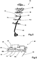
figure 5 est une vue éclatée d'une variante de réalisation du dispositif de commande externe de la bouilloire illustrée enfigure 1 . - la
figure 6 est une vue coupe du dispositif de commande externe illustré enfigure 5 .
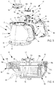
- the
figure 1 is a sectional view of the kettle showing in particular the body, the hot plate, the lower housing and the external control device arranged on a handle; - the
figure 2 is a partial sectional view of thefigure 1 showing the sealed connection between the body, the hot plate and the inner housing; - the
figure 3 is an exploded view of the kettle showing the elements of the external control device integrated into the handle; - the
figure 4 is a partial view of the handle of the kettle showing the assembly of the elements of the external control device illustrated in FIG.figure 3 . - the
figure 5 is an exploded view of an alternative embodiment of the external control device of the kettle illustrated in FIG.figure 1 . - the
figure 6 is a sectional view of the external control device illustrated in FIG.figure 5 .
Tel qu'illustré sur les
Tel qu'illustré sur les
Tel qu'illustré sur les
Tel qu'illustré en
Tel qu'illustré en
Tel qu'illustré en
Ainsi, la partie de la face inférieure de la plaque chauffante 16 située au niveau du rebord 18 est maintenue emboîtée et assemblée, de manière étanche, sur la partie supérieure 13a de la paroi interne 13 du boîtier inférieur 12.Thus, the portion of the lower face of the
Tel qu'illustré sur la
Tel qu'illustré en
Tel qu'illustré en
Tel qu'illustré en
Tel qu'illustré en
Tel qu'illustré en
Dans une variante de réalisation du dispositif de commande externe 49 illustrée aux
La résine 155 est initialement à l'état liquide pour pouvoir être coulée dans la cavité puis durcit pour réaliser une liaison étanche entre les pièces recouvertes, notamment l'étanchéité du passage du câble 65. La résine 155 coulée sera de préférence une résine polyuréthane.The
D'autres caractéristiques sont envisageables dans le cadre de l'invention. On peut notamment prévoir un voyant lumineux sur la carte circuit imprimé et un joint 56 d'étanchéité dans un élastomère transparent, pour indiquer l'allumage de la bouilloire 1. On peut également prévoir des variantes de forme pour le joint d'étanchéité interne 24 et pour le joint d'étanchéité externe 36.Other features are conceivable within the scope of the invention. In particular, it is possible to provide an indicator light on the printed circuit board and a
Claims (12)
- Kettle (1) comprising a body (2), a heating plate (16), a lower casing (12) wherein are housed an inner control device (44) and an outer control device (49) connected to the inner control device (44), and configured to manually actuate said inner control device (44), the body (2) comprising a handle (3), the outer control device (49) being arranged on the handle, the outer control device (49) forming an autonomous sealed module to enable the outside of said kettle to be washed and rinsed with water, the outer control device (49) being connected by a cable (65) to the inner control device (44), characterised in that the sealing means (55, 155) are arranged between the cable (65) and the outer control device (49).
- Kettle according to claim 1, characterised in that the sealing means are arranged between the cable (65) and said lower casing (12).
- Kettle (1) according to claim 2, characterised in that the sealing means are formed by a cable gland arranged on the lower casing.
- Kettle (1) according to claim 2, characterised in that the sealing means are formed by a wall passage (80) overmoulded on the cable.
- Kettle (1) according to claim 1, characterised in that the outer control device (49) is connected to the inner control device (44) by a magnetic connection or a wireless Bluetooth, infrared or wi-fi electromagnetic wave connection.
- Kettle (1) according to claim 1, characterised in that the outer control device (49) comprises:- a lower support (50), the cable (65) passing through the lower support;- a printed circuit board (52) comprising an On/Off switch (53);- an elastomer seal (56) configured to cover the printed circuit board and the switch by moulding their form and by letting a flat peripheral edge (56b) appear;- a tightening part (58) enabling to sandwich the elastomer seal edge between the lower support and the tightening part;- the sealing member (55) is arranged on the lower support and configured to enable the sealed passage of the cable (65), said cable (65) being connected to the printed circuit board.
- Kettle (1) according to claim 6, characterised in that the sealing member is a cable gland (55).
- Kettle (1) according to claim 6, characterised in that the sealing member is a moulded resin (155) surrounding the cable (65).
- Kettle (1) according to claim 8, characterised in that the outer control device (49) comprises:- a lower support (50), the cable (65) passing through the lower support;- a printed circuit board (52) comprising an On/Off switch (53);- an elastomer seal (56) configured to cover the printed circuit board and the switch by moulding their form and by letting a flat peripheral edge (56b) appear;- a tightening part (58) enabling to sandwich the elastomer seal edge between the lower support and the tightening part;- the moulded resin (155) covers a rear face (70) of the printed circuit board and an end of the cable (65), said rear face (70) being bordered by the elastomer seal (56).
- Kettle (1) according to claim 1, characterised in that the handle comprises a first inner part (3a) forming a recess (48) wherein is arranged the outer control device (49) and in that the handle (3) comprises a second covering part (3b) which covers the outer control device (49).
- Kettle (1) according to one of claims 1 to 10, characterised in that:- the lower casing (12) comprises an inner peripheral wall (13) which extends towards the top;- the body (2) comprises a lower part (4b);- the heating plate comprises a lower face (19a, 20a, 33) and a peripheral edge (18);- an outer seal (36) is arranged between the peripheral edge (18) and the lower part (4b), and;- an inner seal (24) is arranged between the inner wall (13) and the lower face (19a, 20a, 33) of the heating plate (2) to prevent any water entering the casing, in particular, water from a leak due to the sealing of the outer seal (36) failing.
- Kettle (1) according to one of claims 1 to 11, characterised in that it comprises a remote power supply base (63), equipped with a male connector (64), the lower casing (12) comprising a base (14) equipped with a female connector (46) configured to receive the male connector, said female connector being configured to ensure that the lower casing is sealed.
Applications Claiming Priority (1)
| Application Number | Priority Date | Filing Date | Title |
|---|---|---|---|
| FR1354548A FR3005842B1 (en) | 2013-05-21 | 2013-05-21 | KETTLE COMPRISING A SEALED CONTROL MODULE |
Publications (2)
| Publication Number | Publication Date |
|---|---|
| EP2805649A1 EP2805649A1 (en) | 2014-11-26 |
| EP2805649B1 true EP2805649B1 (en) | 2018-05-02 |
Family
ID=48906347
Family Applications (1)
| Application Number | Title | Priority Date | Filing Date |
|---|---|---|---|
| EP14167258.4A Active EP2805649B1 (en) | 2013-05-21 | 2014-05-06 | Boiler comprising a sealed control module |
Country Status (4)
| Country | Link |
|---|---|
| EP (1) | EP2805649B1 (en) |
| JP (1) | JP6510184B2 (en) |
| CN (1) | CN104172910B (en) |
| FR (1) | FR3005842B1 (en) |
Cited By (2)
| Publication number | Priority date | Publication date | Assignee | Title |
|---|---|---|---|---|
| EP3669714A1 (en) | 2018-12-17 | 2020-06-24 | Seb S.A. | Electrically insulated sealed boiler for washing in water |
| WO2020190037A1 (en) * | 2019-03-21 | 2020-09-24 | 엘지전자 주식회사 | Electric kettle |
Families Citing this family (11)
| Publication number | Priority date | Publication date | Assignee | Title |
|---|---|---|---|---|
| CN106859313A (en) * | 2015-12-11 | 2017-06-20 | 佛山市云米电器科技有限公司 | Heating vessel, liquid-heating method and device |
| JP6945849B2 (en) * | 2017-09-05 | 2021-10-06 | ピーコック魔法瓶工業株式会社 | Electric kettle |
| WO2020153826A1 (en) * | 2019-01-25 | 2020-07-30 | 엘지전자 주식회사 | Electric kettle |
| KR20200112325A (en) | 2019-03-21 | 2020-10-05 | 엘지전자 주식회사 | electric kettle |
| JP7189437B2 (en) * | 2019-02-15 | 2022-12-14 | タイガー魔法瓶株式会社 | electric water heater |
| KR20200112324A (en) | 2019-03-21 | 2020-10-05 | 엘지전자 주식회사 | electric kettle |
| KR20200112319A (en) | 2019-03-21 | 2020-10-05 | 엘지전자 주식회사 | electric kettle |
| KR20200112321A (en) | 2019-03-21 | 2020-10-05 | 엘지전자 주식회사 | electric kettle |
| KR20200112320A (en) | 2019-03-21 | 2020-10-05 | 엘지전자 주식회사 | electric kettle |
| KR20200112322A (en) | 2019-03-21 | 2020-10-05 | 엘지전자 주식회사 | electric kettle |
| KR20200112327A (en) | 2019-03-21 | 2020-10-05 | 엘지전자 주식회사 | electric kettle |
Family Cites Families (19)
| Publication number | Priority date | Publication date | Assignee | Title |
|---|---|---|---|---|
| DE3143450C2 (en) * | 1981-11-03 | 1986-05-22 | ABC-Elektrogeräte Volz, GmbH & Co, 7312 Kirchheim | Electrically heated kettle |
| JP2581127Y2 (en) * | 1991-07-09 | 1998-09-21 | 象印マホービン株式会社 | Waterproof structure of electric heating container |
| JP3992754B2 (en) * | 1997-12-02 | 2007-10-17 | コーニンクレッカ フィリップス エレクトロニクス エヌ ヴィ | Heating vessel and method for controlling the heating element of such a vessel |
| JP3026295B1 (en) * | 1999-02-26 | 2000-03-27 | 日本精機株式会社 | Sealed structure and moving object detector provided with sealed structure |
| GB2382225C (en) * | 2001-11-16 | 2007-10-10 | Kettle Solutions Ltd | Switch for water boiling appliance such as a kettle |
| JP4110383B2 (en) * | 2002-11-01 | 2008-07-02 | オムロン株式会社 | Proximity sensor |
| JP4214902B2 (en) * | 2003-12-03 | 2009-01-28 | タイガー魔法瓶株式会社 | Electric hot water storage container |
| JP5009044B2 (en) * | 2007-05-16 | 2012-08-22 | 象印マホービン株式会社 | Electric pot |
| CN201064394Y (en) * | 2007-06-21 | 2008-05-28 | 广东伟德利电器制造有限公司 | Novel heating mode electric heating kettle |
| GB2460620B (en) | 2008-03-07 | 2012-12-12 | Otter Controls Ltd | Electrical appliances and components |
| CN201213711Y (en) | 2008-05-30 | 2009-04-01 | 广东德豪润达电气股份有限公司 | Wireless electric heating kettle |
| CN201379424Y (en) * | 2009-03-10 | 2010-01-13 | 古延民 | Base of electric kettle |
| CN201398847Y (en) * | 2009-04-07 | 2010-02-10 | 冯启斌 | Electric pot controlled by a handle electronically |
| CN201510119U (en) * | 2009-09-09 | 2010-06-23 | 彭建平 | Electric pressure cooker with waterproof switch box |
| JP5821184B2 (en) * | 2010-12-16 | 2015-11-24 | タイガー魔法瓶株式会社 | Electric kettle |
| CN202168556U (en) * | 2011-08-23 | 2012-03-21 | 文创太阳能(福建)科技有限公司 | Solar water kettle |
| JP5755094B2 (en) * | 2011-09-20 | 2015-07-29 | 象印マホービン株式会社 | Hand-poured equipment |
| CN202505036U (en) * | 2012-04-19 | 2012-10-31 | 胡晋铭 | Electric kettle |
| CN202820927U (en) * | 2012-07-09 | 2013-03-27 | 广东格兰仕集团有限公司 | Leakproof electric kettle |
-
2013
- 2013-05-21 FR FR1354548A patent/FR3005842B1/en active Active
-
2014
- 2014-05-06 EP EP14167258.4A patent/EP2805649B1/en active Active
- 2014-05-19 CN CN201410210377.XA patent/CN104172910B/en active Active
- 2014-05-20 JP JP2014104375A patent/JP6510184B2/en active Active
Non-Patent Citations (1)
| Title |
|---|
| None * |
Cited By (2)
| Publication number | Priority date | Publication date | Assignee | Title |
|---|---|---|---|---|
| EP3669714A1 (en) | 2018-12-17 | 2020-06-24 | Seb S.A. | Electrically insulated sealed boiler for washing in water |
| WO2020190037A1 (en) * | 2019-03-21 | 2020-09-24 | 엘지전자 주식회사 | Electric kettle |
Also Published As
| Publication number | Publication date |
|---|---|
| JP6510184B2 (en) | 2019-05-08 |
| CN104172910A (en) | 2014-12-03 |
| FR3005842A1 (en) | 2014-11-28 |
| JP2014226555A (en) | 2014-12-08 |
| CN104172910B (en) | 2018-07-27 |
| FR3005842B1 (en) | 2015-12-04 |
| EP2805649A1 (en) | 2014-11-26 |
Similar Documents
| Publication | Publication Date | Title |
|---|---|---|
| EP2805649B1 (en) | Boiler comprising a sealed control module | |
| EP2805650B1 (en) | Boiler comprising a sealed housing | |
| EP2016878B1 (en) | Pressure cooker equipped with a fixed gripping element on the tank | |
| FR2975882A1 (en) | SAFETY VALVE FOR PRESSURIZED COOKING APPARATUS AND DEVICE INCLUDING SUCH A VALVE | |
| FR2882434A3 (en) | INDUCTIVE PRESSURE SENSOR, ESPECIALLY FOR HOUSEHOLD APPLIANCES, BOILERS AND OTHER | |
| EP2526842B1 (en) | Lid for closing a working container of a household cooking appliance | |
| EP3184007B1 (en) | Reinforced pressure cooker | |
| EP0872201B1 (en) | Electric boiler | |
| EP3088599B1 (en) | Household ironing appliance comprising a steam generator provided with a discharge opening | |
| CA2272213C (en) | Device or instrument manufacturing process by moulding from a cast and the device or tool manufactured through this process | |
| EP1117318B1 (en) | Electrical appliance for heating liquids, comprising a heating base and glass walls | |
| EP3669714B1 (en) | Electrically insulated sealed boiler for washing in water | |
| EP1504705B1 (en) | Electrical cooking appliance containing a drain base | |
| FR2806283A1 (en) | Electrically heated kettle has a separate base unit having the heating element, connections, control system and hotplate sealingly clipped to the water container | |
| FR2984713A1 (en) | CULINARY ELECTRICAL APPARATUS AND RELATED SECURITY MEANS | |
| EP2436289B1 (en) | Electrical cooking appliance comprising a hinged lid provided with a condensate-recovery device | |
| EP2609942A1 (en) | Device for checking the return of fluids built into a breast pump | |
| EP2103238B1 (en) | Cooking device cover comprising a dual-wall window | |
| WO2020115245A1 (en) | Steamer accessory with silicone-coated support device | |
| EP0188957A1 (en) | Plastic spout for a pressurized container | |
| FR3072263A1 (en) | ELECTRIC COOKING APPARATUS COMPRISING A DRAIN SUPPORT WITH A COVER | |
| FR2967879A1 (en) | Lid for e.g. multi-purpose cooking apparatus, has joint arranged at side of lid during assembling of lid with apparatus between adjacent metal elements to allow sealed closing of lid, and plastic element arranged among metal elements | |
| WO2003032795A1 (en) | Cooking appliance with a vessel comprising a draining device with a filter | |
| EP0815785B1 (en) | Lid for a cooking vessel | |
| FR3083687A1 (en) | COVER WITH A GLASS PIECE |
Legal Events
| Date | Code | Title | Description |
|---|---|---|---|
| PUAI | Public reference made under article 153(3) epc to a published international application that has entered the european phase |
Free format text: ORIGINAL CODE: 0009012 |
|
| 17P | Request for examination filed |
Effective date: 20140506 |
|
| AK | Designated contracting states |
Kind code of ref document: A1 Designated state(s): AL AT BE BG CH CY CZ DE DK EE ES FI FR GB GR HR HU IE IS IT LI LT LU LV MC MK MT NL NO PL PT RO RS SE SI SK SM TR |
|
| AX | Request for extension of the european patent |
Extension state: BA ME |
|
| R17P | Request for examination filed (corrected) |
Effective date: 20150519 |
|
| RBV | Designated contracting states (corrected) |
Designated state(s): AL AT BE BG CH CY CZ DE DK EE ES FI FR GB GR HR HU IE IS IT LI LT LU LV MC MK MT NL NO PL PT RO RS SE SI SK SM TR |
|
| 17Q | First examination report despatched |
Effective date: 20151118 |
|
| RAP1 | Party data changed (applicant data changed or rights of an application transferred) |
Owner name: SEB S.A. |
|
| GRAP | Despatch of communication of intention to grant a patent |
Free format text: ORIGINAL CODE: EPIDOSNIGR1 |
|
| INTG | Intention to grant announced |
Effective date: 20180122 |
|
| GRAS | Grant fee paid |
Free format text: ORIGINAL CODE: EPIDOSNIGR3 |
|
| GRAA | (expected) grant |
Free format text: ORIGINAL CODE: 0009210 |
|
| AK | Designated contracting states |
Kind code of ref document: B1 Designated state(s): AL AT BE BG CH CY CZ DE DK EE ES FI FR GB GR HR HU IE IS IT LI LT LU LV MC MK MT NL NO PL PT RO RS SE SI SK SM TR |
|
| REG | Reference to a national code |
Ref country code: GB Ref legal event code: FG4D Free format text: NOT ENGLISH |
|
| REG | Reference to a national code |
Ref country code: CH Ref legal event code: EP Ref country code: AT Ref legal event code: REF Ref document number: 994345 Country of ref document: AT Kind code of ref document: T Effective date: 20180515 |
|
| REG | Reference to a national code |
Ref country code: DE Ref legal event code: R096 Ref document number: 602014024750 Country of ref document: DE Ref country code: IE Ref legal event code: FG4D Free format text: LANGUAGE OF EP DOCUMENT: FRENCH |
|
| REG | Reference to a national code |
Ref country code: FR Ref legal event code: PLFP Year of fee payment: 5 |
|
| REG | Reference to a national code |
Ref country code: NL Ref legal event code: MP Effective date: 20180502 |
|
| REG | Reference to a national code |
Ref country code: LT Ref legal event code: MG4D |
|
| PG25 | Lapsed in a contracting state [announced via postgrant information from national office to epo] |
Ref country code: SE Free format text: LAPSE BECAUSE OF FAILURE TO SUBMIT A TRANSLATION OF THE DESCRIPTION OR TO PAY THE FEE WITHIN THE PRESCRIBED TIME-LIMIT Effective date: 20180502 Ref country code: ES Free format text: LAPSE BECAUSE OF FAILURE TO SUBMIT A TRANSLATION OF THE DESCRIPTION OR TO PAY THE FEE WITHIN THE PRESCRIBED TIME-LIMIT Effective date: 20180502 Ref country code: LT Free format text: LAPSE BECAUSE OF FAILURE TO SUBMIT A TRANSLATION OF THE DESCRIPTION OR TO PAY THE FEE WITHIN THE PRESCRIBED TIME-LIMIT Effective date: 20180502 Ref country code: NO Free format text: LAPSE BECAUSE OF FAILURE TO SUBMIT A TRANSLATION OF THE DESCRIPTION OR TO PAY THE FEE WITHIN THE PRESCRIBED TIME-LIMIT Effective date: 20180802 Ref country code: FI Free format text: LAPSE BECAUSE OF FAILURE TO SUBMIT A TRANSLATION OF THE DESCRIPTION OR TO PAY THE FEE WITHIN THE PRESCRIBED TIME-LIMIT Effective date: 20180502 Ref country code: BG Free format text: LAPSE BECAUSE OF FAILURE TO SUBMIT A TRANSLATION OF THE DESCRIPTION OR TO PAY THE FEE WITHIN THE PRESCRIBED TIME-LIMIT Effective date: 20180802 |
|
| PG25 | Lapsed in a contracting state [announced via postgrant information from national office to epo] |
Ref country code: RS Free format text: LAPSE BECAUSE OF FAILURE TO SUBMIT A TRANSLATION OF THE DESCRIPTION OR TO PAY THE FEE WITHIN THE PRESCRIBED TIME-LIMIT Effective date: 20180502 Ref country code: NL Free format text: LAPSE BECAUSE OF FAILURE TO SUBMIT A TRANSLATION OF THE DESCRIPTION OR TO PAY THE FEE WITHIN THE PRESCRIBED TIME-LIMIT Effective date: 20180502 Ref country code: HR Free format text: LAPSE BECAUSE OF FAILURE TO SUBMIT A TRANSLATION OF THE DESCRIPTION OR TO PAY THE FEE WITHIN THE PRESCRIBED TIME-LIMIT Effective date: 20180502 Ref country code: LV Free format text: LAPSE BECAUSE OF FAILURE TO SUBMIT A TRANSLATION OF THE DESCRIPTION OR TO PAY THE FEE WITHIN THE PRESCRIBED TIME-LIMIT Effective date: 20180502 Ref country code: GR Free format text: LAPSE BECAUSE OF FAILURE TO SUBMIT A TRANSLATION OF THE DESCRIPTION OR TO PAY THE FEE WITHIN THE PRESCRIBED TIME-LIMIT Effective date: 20180803 |
|
| REG | Reference to a national code |
Ref country code: DE Ref legal event code: R119 Ref document number: 602014024750 Country of ref document: DE |
|
| REG | Reference to a national code |
Ref country code: CH Ref legal event code: PL |
|
| REG | Reference to a national code |
Ref country code: AT Ref legal event code: MK05 Ref document number: 994345 Country of ref document: AT Kind code of ref document: T Effective date: 20180502 |
|
| REG | Reference to a national code |
Ref country code: BE Ref legal event code: MM Effective date: 20180531 |
|
| PG25 | Lapsed in a contracting state [announced via postgrant information from national office to epo] |
Ref country code: SK Free format text: LAPSE BECAUSE OF FAILURE TO SUBMIT A TRANSLATION OF THE DESCRIPTION OR TO PAY THE FEE WITHIN THE PRESCRIBED TIME-LIMIT Effective date: 20180502 Ref country code: EE Free format text: LAPSE BECAUSE OF FAILURE TO SUBMIT A TRANSLATION OF THE DESCRIPTION OR TO PAY THE FEE WITHIN THE PRESCRIBED TIME-LIMIT Effective date: 20180502 Ref country code: PL Free format text: LAPSE BECAUSE OF FAILURE TO SUBMIT A TRANSLATION OF THE DESCRIPTION OR TO PAY THE FEE WITHIN THE PRESCRIBED TIME-LIMIT Effective date: 20180502 Ref country code: DK Free format text: LAPSE BECAUSE OF FAILURE TO SUBMIT A TRANSLATION OF THE DESCRIPTION OR TO PAY THE FEE WITHIN THE PRESCRIBED TIME-LIMIT Effective date: 20180502 Ref country code: RO Free format text: LAPSE BECAUSE OF FAILURE TO SUBMIT A TRANSLATION OF THE DESCRIPTION OR TO PAY THE FEE WITHIN THE PRESCRIBED TIME-LIMIT Effective date: 20180502 Ref country code: AT Free format text: LAPSE BECAUSE OF FAILURE TO SUBMIT A TRANSLATION OF THE DESCRIPTION OR TO PAY THE FEE WITHIN THE PRESCRIBED TIME-LIMIT Effective date: 20180502 Ref country code: CZ Free format text: LAPSE BECAUSE OF FAILURE TO SUBMIT A TRANSLATION OF THE DESCRIPTION OR TO PAY THE FEE WITHIN THE PRESCRIBED TIME-LIMIT Effective date: 20180502 |
|
| REG | Reference to a national code |
Ref country code: IE Ref legal event code: MM4A |
|
| PG25 | Lapsed in a contracting state [announced via postgrant information from national office to epo] |
Ref country code: LI Free format text: LAPSE BECAUSE OF NON-PAYMENT OF DUE FEES Effective date: 20180531 Ref country code: IT Free format text: LAPSE BECAUSE OF FAILURE TO SUBMIT A TRANSLATION OF THE DESCRIPTION OR TO PAY THE FEE WITHIN THE PRESCRIBED TIME-LIMIT Effective date: 20180502 Ref country code: CH Free format text: LAPSE BECAUSE OF NON-PAYMENT OF DUE FEES Effective date: 20180531 Ref country code: SM Free format text: LAPSE BECAUSE OF FAILURE TO SUBMIT A TRANSLATION OF THE DESCRIPTION OR TO PAY THE FEE WITHIN THE PRESCRIBED TIME-LIMIT Effective date: 20180502 |
|
| PLBE | No opposition filed within time limit |
Free format text: ORIGINAL CODE: 0009261 |
|
| STAA | Information on the status of an ep patent application or granted ep patent |
Free format text: STATUS: NO OPPOSITION FILED WITHIN TIME LIMIT |
|
| PG25 | Lapsed in a contracting state [announced via postgrant information from national office to epo] |
Ref country code: MC Free format text: LAPSE BECAUSE OF FAILURE TO SUBMIT A TRANSLATION OF THE DESCRIPTION OR TO PAY THE FEE WITHIN THE PRESCRIBED TIME-LIMIT Effective date: 20180502 Ref country code: LU Free format text: LAPSE BECAUSE OF NON-PAYMENT OF DUE FEES Effective date: 20180506 |
|
| 26N | No opposition filed |
Effective date: 20190205 |
|
| PG25 | Lapsed in a contracting state [announced via postgrant information from national office to epo] |
Ref country code: DE Free format text: LAPSE BECAUSE OF NON-PAYMENT OF DUE FEES Effective date: 20181201 Ref country code: IE Free format text: LAPSE BECAUSE OF NON-PAYMENT OF DUE FEES Effective date: 20180506 |
|
| PG25 | Lapsed in a contracting state [announced via postgrant information from national office to epo] |
Ref country code: BE Free format text: LAPSE BECAUSE OF NON-PAYMENT OF DUE FEES Effective date: 20180531 Ref country code: SI Free format text: LAPSE BECAUSE OF FAILURE TO SUBMIT A TRANSLATION OF THE DESCRIPTION OR TO PAY THE FEE WITHIN THE PRESCRIBED TIME-LIMIT Effective date: 20180502 |
|
| PG25 | Lapsed in a contracting state [announced via postgrant information from national office to epo] |
Ref country code: AL Free format text: LAPSE BECAUSE OF FAILURE TO SUBMIT A TRANSLATION OF THE DESCRIPTION OR TO PAY THE FEE WITHIN THE PRESCRIBED TIME-LIMIT Effective date: 20180502 |
|
| PG25 | Lapsed in a contracting state [announced via postgrant information from national office to epo] |
Ref country code: MT Free format text: LAPSE BECAUSE OF FAILURE TO SUBMIT A TRANSLATION OF THE DESCRIPTION OR TO PAY THE FEE WITHIN THE PRESCRIBED TIME-LIMIT Effective date: 20180502 |
|
| PG25 | Lapsed in a contracting state [announced via postgrant information from national office to epo] |
Ref country code: TR Free format text: LAPSE BECAUSE OF FAILURE TO SUBMIT A TRANSLATION OF THE DESCRIPTION OR TO PAY THE FEE WITHIN THE PRESCRIBED TIME-LIMIT Effective date: 20180502 |
|
| PG25 | Lapsed in a contracting state [announced via postgrant information from national office to epo] |
Ref country code: HU Free format text: LAPSE BECAUSE OF FAILURE TO SUBMIT A TRANSLATION OF THE DESCRIPTION OR TO PAY THE FEE WITHIN THE PRESCRIBED TIME-LIMIT; INVALID AB INITIO Effective date: 20140506 Ref country code: PT Free format text: LAPSE BECAUSE OF FAILURE TO SUBMIT A TRANSLATION OF THE DESCRIPTION OR TO PAY THE FEE WITHIN THE PRESCRIBED TIME-LIMIT Effective date: 20180502 |
|
| PG25 | Lapsed in a contracting state [announced via postgrant information from national office to epo] |
Ref country code: CY Free format text: LAPSE BECAUSE OF FAILURE TO SUBMIT A TRANSLATION OF THE DESCRIPTION OR TO PAY THE FEE WITHIN THE PRESCRIBED TIME-LIMIT Effective date: 20180502 Ref country code: MK Free format text: LAPSE BECAUSE OF NON-PAYMENT OF DUE FEES Effective date: 20180502 |
|
| PG25 | Lapsed in a contracting state [announced via postgrant information from national office to epo] |
Ref country code: IS Free format text: LAPSE BECAUSE OF FAILURE TO SUBMIT A TRANSLATION OF THE DESCRIPTION OR TO PAY THE FEE WITHIN THE PRESCRIBED TIME-LIMIT Effective date: 20180902 |
|
| PGFP | Annual fee paid to national office [announced via postgrant information from national office to epo] |
Ref country code: FR Payment date: 20230523 Year of fee payment: 10 |
|
| PGFP | Annual fee paid to national office [announced via postgrant information from national office to epo] |
Ref country code: GB Payment date: 20230519 Year of fee payment: 10 |