EP2609942A1 - Device for checking the return of fluids built into a breast pump - Google Patents
Device for checking the return of fluids built into a breast pump Download PDFInfo
- Publication number
- EP2609942A1 EP2609942A1 EP12306517.9A EP12306517A EP2609942A1 EP 2609942 A1 EP2609942 A1 EP 2609942A1 EP 12306517 A EP12306517 A EP 12306517A EP 2609942 A1 EP2609942 A1 EP 2609942A1
- Authority
- EP
- European Patent Office
- Prior art keywords
- return valve
- return
- valve
- nipple
- cylindrical
- Prior art date
- Legal status (The legal status is an assumption and is not a legal conclusion. Google has not performed a legal analysis and makes no representation as to the accuracy of the status listed.)
- Withdrawn
Links
Images


Classifications
-
- A—HUMAN NECESSITIES
- A61—MEDICAL OR VETERINARY SCIENCE; HYGIENE
- A61M—DEVICES FOR INTRODUCING MEDIA INTO, OR ONTO, THE BODY; DEVICES FOR TRANSDUCING BODY MEDIA OR FOR TAKING MEDIA FROM THE BODY; DEVICES FOR PRODUCING OR ENDING SLEEP OR STUPOR
- A61M1/00—Suction or pumping devices for medical purposes; Devices for carrying-off, for treatment of, or for carrying-over, body-liquids; Drainage systems
- A61M1/06—Milking pumps
-
- A—HUMAN NECESSITIES
- A61—MEDICAL OR VETERINARY SCIENCE; HYGIENE
- A61M—DEVICES FOR INTRODUCING MEDIA INTO, OR ONTO, THE BODY; DEVICES FOR TRANSDUCING BODY MEDIA OR FOR TAKING MEDIA FROM THE BODY; DEVICES FOR PRODUCING OR ENDING SLEEP OR STUPOR
- A61M1/00—Suction or pumping devices for medical purposes; Devices for carrying-off, for treatment of, or for carrying-over, body-liquids; Drainage systems
- A61M1/71—Suction drainage systems
- A61M1/78—Means for preventing overflow or contamination of the pumping systems
Definitions
- the invention relates to the technical field of breast milk expression assemblies which are designed with a breast shield including a portion of the breast and adapting to the body of a bottle.
- the breast milk expression system (K) commonly known in the professional world as "expression kit” thus comprises a bottle (1) and a nipple (2) which is screwed by its base (2a). on the threaded portion (1a) of the neck of the bottle.
- the nipple (2) also comprises an end portion called “breast end” (2b) which is positioned on the breast of the nursing person.
- the nipple is arranged in the interior volume of the base (2a), with a cylindrical sleeve (2c) which reduces the flow passage and transfer of milk into the bottle.
- This sleeve is capable of receiving a non-return valve (3) which is made with a cylindrical ring-shaped base (3a) extended by two lips (3b) defining between them an opening (3c) for the passage of milk.
- This non-return valve is made of an elastomeric material having a certain deformation capacity and can be mounted on the sleeve (2c) to ensure its fixing and positioning.
- the two lips (3b) facing one another are also a gripping means by an operator when it is necessary to proceed with the cleaning of the non-return valve.
- the said lips as represented at Figures 2 and 3 , are inclined relative to each other, downwards, and make it possible, by forming a nozzle, to discharge the milk into the bottle.
- this non-return valve (3) is in no way protected in itself from the external environment and especially that it constitutes in itself by the seizure of the lips by the fingers of the operator the means of gripping, setting up or removing from the nipple shield.
- the hygiene conditions are therefore very unfavorable, without counting moreover the deformation of said lips by the multiplicity of seizure operations for cleaning.
- the various repeated manipulations of placing the non-return valve on the sleeve (2c) inside the base of the nipple cause deformation and widening of the base of the non-return valve with then risks of escape of the non-return valve in the bottle.
- the Applicant's approach was therefore to find a solution that allows an improvement in hygiene with respect to the handling of the nipple, the cleaning of the non-return valve, and which also avoids the risks of deterioration in the long of the valve part fitting on the receiving sleeve provided on the nipple.
- the Applicant's approach has also been to find a solution that avoids any contact of the operator or the user directly with the non-return valve and in particular during the cleaning phases.
- the fluid anti-return device incorporated in a breast milk expression assembly comprising a bottle and a breast shield having at one end part a breast end, the said nipple being arranged for the receipt of a non-return valve, is remarkable in that the said nipple is arranged for the reception of a non-return valve, and a tubular support means surrounding said check valve and overflowing with respect to the end of said check valve so as to ensure its total protection and protect it from unintentional contact of the fingers of the user.
- the fluid anti-return device incorporated in a breast milk expression assembly is remarkable in that the means of protection form support and is arranged internally to receive and maintain a non-return valve, said support means being capable of being positioned relative to the sleeve portion formed in the inner portion of the constituent base of the breast end, the said medium support being of great height and ensuring the protection of the non-return valve with a height of overflow relative to the lower end of the check valve between one millimeter and several centimeters in order to prevent contact with the fingers of the user, and constituting the means of gripping and manipulation by the user and leading into the said bottle.
- the fluid anti-return device incorporated in a breast milk expression assembly is remarkable in that the said support means comprises two components assembled together and enclosing a non-return valve, the first component being positioned on said sleeve, and the other component providing a dual function of a protective part of the non-return valve and of the other hand being the exclusive means of grip and manipulation by the user, said constituent opening into the bottle.
- the nipple is arranged directly by molding with the protection means of the non-return valve
- the breast milk expression kit is referenced by (K) and comprises as before a bottle (1), a nipple (2).
- the feeding bottle comprises a neck (1a) on which the cylindrical base (2a) of the nipple is screwed.
- the configuration thereof and in particular its part "breast end" is established in any appropriate manner.
- the base (2a) internally comprises a cylindrical portion or duct opening into the upper part of the nipple and thus allowing the transfer of the milk collected in the bottle.
- the said nipple is arranged for receiving a non-return valve, and a tubular means surrounding said check valve so as to ensure its total protection and overflow relative to the end said non-return valve to provide a function of prohibiting the passage of the user's fingers.
- said tubular means constitutes in itself a means of gripping and manipulation. Different embodiments of the invention are thus described.
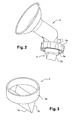
- FIG. 1 a first variant of the non-return device and fixing the non-return valve (3).
- the device comprises at least one support means (4) of tubular configuration arranged internally to receive and maintain the non-return valve (3), said support means being capable of being positioned relative to the sleeve portion (2c) formed in the inner part of the base (2a) constituting the breast end (2b).
- the said support means (4) is of great height and provides protection for the non-return valve, and constituting the gripping and manipulation means by the user and opening into said bottle.
- the support means (4) thus internally has a flange (4a) configured in the form of a with a cylindrical bearing surface (4b) on which is positioned a cylindrical ring (3a) formed on the base of the non-return valve (3).
- the support means (4) has lips (3b) which converge to define an opening space (3c) of the milk passage.
- the support means thus produced is monobloc and is obtained by molding. In its upper part, it is positioned on the sleeve portion (2c) formed in the base (2a) of the breast end.
- the height of the support means (4) is such that it overflows relative to the end (3d) of the non-return valve. Said means (4) protrudes from said end between one millimeter and several centimeters and advantageously of the order of 3 centimeters.
- the support means (4) has an opening diameter (d) at its end of between 0.5 and 3 centimeters (s).
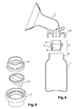
- the support means of the non-return valve is thus made from an assembly and comprises two constituents (10) and (11) which are capable of being assembled together in a fixed or removable manner and enclosing a nonreturn valve (12), the first component (10) being capable of being positioned on the inner sleeve (2c) of the base (2a) of the while the other component (11) provides a double function, on the one hand protecting the non-return valve (12) and on the other hand being the exclusive means of grip and manipulation by the user when maintenance and cleaning operations of said non-return valve, said component (11) opening into the bottle.
- the first component (10) comprises a central base (10a) of circular configuration which is extended on one side by a cylindrical bearing surface (10b), which is capable of coming to bear on the sleeve (2c) mentioned above, and of other by a cylindrical bearing (10c) of larger diameter.
- the latter has at the end on its front face (10d) a protruding extension (10e) established over the entire disc surface of said front face.
- the base (10a) also defines a horizontal support plane (10f) which is likely to be in contact with the non-return valve (12).
- the second component (11) comprises a circular central base (11a) extending on one side by a cylindrical surface (11b) able to surround the cylindrical surface (10c) of the component (10) and on the other side by a cylindrical bearing (11c) of greater length forming a protective sleeve.
- the central base (11a) is internally extended with a protruding shape (11d) projecting upwards and capable of being in contact with the non-return valve (12) by its ring (12a).
- the central base (11a) comprises a horizontal bearing plane (11e) against which the disc front face (10d) bears against the formation of a circular groove (11f) capable of receiving the projecting form (10e) above formed on the constituent (10).
- the component (10) is centered within the component (11).
- the non-return valve (12), as shown figure 8 comprises a cylindrical crown (12a) upper which is extended by two lips (12b) oriented inclined relative to each other from said crown and meeting at the end projecting. These lips leave an opening (12c) at the end for the passage of the collected milk.
- the cylindrical ring (12a) is thus positioned in the interior space formed between the constituents (10) and (11) as shown figure 6 , and more specifically in the volume defined between their bases (10a) and (11a).
- the projecting shape (11c) established on the base (11a) of the second component comes into contact and bears against the crown portion of the non-return valve.
- Said valve being made of an elastomeric material, it is deformed substantially at the point of penetration of the aforementioned projecting shape (11c) thus ensuring a locking in position.
- connection between the constituents (11) and (12) can be fixed or removable. There may be a tight fit after installation of the check valve. There may be a connection by clipping engagement configurations using complementary male-female forms formed on the facing portions of said components.
- the height of the cylindrical seat (11c) is greater than the height of the lips (12b) of the non-return valve so as to protect them.
- the device forms a single assembly constituting a kind of tip which is then positioned on the sleeve (2c) receiver provided inside the base of the nipple shield.
- This The assembly can be easily disassembled and subsequently manipulated for the purpose of cleaning the non-return valve. It is not necessary to disassemble the latter with respect to the components (10) and (11) of the device. Handling of the device is done from the outside without contact with the non-return valve and thus under optimized hygiene conditions. The non-return valve is not handled per se and is therefore not deformed with use.
- the height of the cylindrical bearing surface (11c) of the component (11) is large enough to prevent penetration of the user's fingers with contact on the non-return valve.
- Complementary sealing elements may be provided in the positioning and connection of the device on the sleeve in the base of the nipple. These are, for example, O-rings or the like.
- the constituents (10) and (11) may comprise lights, of lower section than the passage of a finger.
- the non-return valve is made of an elastomeric material and can be sterilized and, if necessary, both components (10) and (11).
- the constituents (10) and (11) may be made of any material, for example plastic by being rigid, and may have a visual effect of transparency or opaque. It can also be envisaged without departing from the scope of the invention that the constituents (10) and (11) can constitute in themselves a single piece by overmolding while allowing the introduction and clipping in position of the non-return valve .
- FIG 11 another embodiment of the invention that the nipple is directly arranged during its manufacture with on the one hand the sleeve portion (2c) for receiving the non-return valve but also with the means (4) which protects the said non-return valve by being of sufficient height to protrude from the end of the said flapper.
- FIG 12 an alternative embodiment of the non-return valve.
- the latter is capable of receiving, at the bottom end, directly or in an attached manner, a perforated means (13) in the form of a grid, for example, so as to prevent the penetration of a finger.
- This means is attached, clipped or otherwise on said end of the check valve, while allowing the flow of milk through the openings (13a).
- the height of the support means (4) or the constituent (11) is such that it allows the limited accessibility of the user to the end portion of the lips of the non-return valve for purposes of seizure .
Abstract
Description
L'invention se rattache au secteur technique des ensembles d'expression de lait maternel qui sont conçus avec une téterelle incluant une partie bout de sein et s'adaptant sur le corps d'un biberon.The invention relates to the technical field of breast milk expression assemblies which are designed with a breast shield including a portion of the breast and adapting to the body of a bottle.
On a illustré selon les
On connaît par le brevet
On connaît également par le brevet
La problématique réside dans le fait que ce clapet anti-retour (3) n'est nullement protégé en soi de l'environnement extérieur et surtout qu'il constitue en lui-même par la saisie des lèvres par les doigts de l'opérateur le moyen de préhension, de mise en place ou d'enlèvement par rapport à la téterelle. Les conditions d'hygiène sont donc très défavorables, sans compter en plus sur la déformation des dites lèvres par la multiplicité d'opérations de saisie pour nettoyage. On observe également que les différentes manipulations, à répétition, de mise en place du clapet anti-retour sur le manchon (2c) à l'intérieur de la base de la téterelle entraînent une déformation et un élargissement de la base du clapet anti-retour avec alors des risques d'échappement du clapet anti-retour dans le biberon.The problem lies in the fact that this non-return valve (3) is in no way protected in itself from the external environment and especially that it constitutes in itself by the seizure of the lips by the fingers of the operator the means of gripping, setting up or removing from the nipple shield. The hygiene conditions are therefore very unfavorable, without counting moreover the deformation of said lips by the multiplicity of seizure operations for cleaning. It is also observed that the various repeated manipulations of placing the non-return valve on the sleeve (2c) inside the base of the nipple cause deformation and widening of the base of the non-return valve with then risks of escape of the non-return valve in the bottle.
La démarche du Demandeur a donc été de rechercher une solution qui permette une amélioration de l'hygiène quant à la manipulation de la téterelle, du nettoyage du clapet anti-retour, et qui évite aussi les risques de détérioration à la longue de la partie clapet s'adaptant sur le manchon récepteur prévu sur la téterelle.The Applicant's approach was therefore to find a solution that allows an improvement in hygiene with respect to the handling of the nipple, the cleaning of the non-return valve, and which also avoids the risks of deterioration in the long of the valve part fitting on the receiving sleeve provided on the nipple.
La démarche du Demandeur a aussi été de rechercher une solution qui évite tout contact de l'opérateur ou de l'utilisateur directement avec le clapet anti-retour et notamment lors des phases de nettoyage.The Applicant's approach has also been to find a solution that avoids any contact of the operator or the user directly with the non-return valve and in particular during the cleaning phases.
La solution apportée par le Demandeur répond à ces objectifs d'une manière simple et pratique.The solution provided by the Applicant meets these objectives in a simple and practical way.
Selon une première caractéristique de l'invention, le dispositif anti-retour de fluides incorporé dans un ensemble d'expression de lait maternel comprenant un biberon et une téterelle présentant en une partie d'extrémité un bout de sein, la dite téterelle étant agencée pour la réception d'un clapet anti-retour, est remarquable en ce que la dite téterelle est agencée pour la réception d'un clapet anti-retour, et d'un moyen support tubulaire entourant le dit clapet anti-retour et débordant par rapport à l'extrémité dudit clapet anti-retour de manière à assurer sa protection totale et le protéger de tout contact involontaire des doigts de l'utilisateur.According to a first feature of the invention, the fluid anti-return device incorporated in a breast milk expression assembly comprising a bottle and a breast shield having at one end part a breast end, the said nipple being arranged for the receipt of a non-return valve, is remarkable in that the said nipple is arranged for the reception of a non-return valve, and a tubular support means surrounding said check valve and overflowing with respect to the end of said check valve so as to ensure its total protection and protect it from unintentional contact of the fingers of the user.
Selon une autre caractéristique de l'invention, le dispositif anti-retour de fluides incorporé dans un ensemble d'expression de lait maternel, la dite téterelle étant agencée dans le volume intérieur de sa base avec un manchon cylindrique, est remarquable en ce que le moyen de protection forme support et est agencé intérieurement pour recevoir et maintenir un clapet anti-retour, le dit moyen support étant susceptible d'être positionné par rapport à la partie manchon formée dans la partie intérieure de la base constitutive du bout de sein, le dit moyen support étant de grande hauteur et assurant la protection du clapet anti-retour avec une hauteur de débordement par rapport à l'extrémité inférieure du clapet anti-retour comprise entre un millimètre et plusieurs centimètres afin d'empêcher le contact avec les doigts de l'utilisateur, et constituant le moyen de préhension et de manipulation par l'utilisateur et débouchant dans le dit biberon.According to another characteristic of the invention, the fluid anti-return device incorporated in a breast milk expression assembly, the said nipple being arranged in the interior volume of its base with a cylindrical sleeve, is remarkable in that the means of protection form support and is arranged internally to receive and maintain a non-return valve, said support means being capable of being positioned relative to the sleeve portion formed in the inner portion of the constituent base of the breast end, the said medium support being of great height and ensuring the protection of the non-return valve with a height of overflow relative to the lower end of the check valve between one millimeter and several centimeters in order to prevent contact with the fingers of the user, and constituting the means of gripping and manipulation by the user and leading into the said bottle.
Selon une autre caractéristique de l'invention, le dispositif anti-retour de fluides incorporé dans un ensemble d'expression de lait maternel, la dite téterelle étant agencée dans le volume intérieur de sa base avec un manchon cylindrique, est remarquable en ce que le dit moyen support comprend deux constituants assemblés entre eux et enserrant un clapet anti-retour, le premier constituant étant positionné sur le dit manchon, et l'autre constituant assurant une double fonction d'une part de protection du clapet anti-retour et d'autre part constituant le moyen exclusif de préhension et de manipulation par l'utilisateur, le dit constituant débouchant dans le biberon.According to another characteristic of the invention, the fluid anti-return device incorporated in a breast milk expression assembly, the said nipple being arranged in the interior volume of its base with a cylindrical sleeve, is remarkable in that the said support means comprises two components assembled together and enclosing a non-return valve, the first component being positioned on said sleeve, and the other component providing a dual function of a protective part of the non-return valve and of the other hand being the exclusive means of grip and manipulation by the user, said constituent opening into the bottle.
Selon une autre caractéristique, la téterelle est agencée directement par moulage avec le moyen de protection du clapet anti-retourAccording to another characteristic, the nipple is arranged directly by molding with the protection means of the non-return valve
Ces caractéristiques et d'autres encore ressortiront bien de la suite de la description.These and other characteristics will be apparent from the rest of the description.
Pour fixer l'objet de l'invention illustré d'une manière non limitative aux figures des dessins où :
- La
figure 1 est une vue éclatée avant montage d'un kit d'expression de lait maternel selon l'art antérieur en illustrant la partie téterelle, le biberon et le clapet anti-retour, - La
figure 2 est une vue à grande échelle selon lafigure 1 illustrant le montage du clapet anti-retour sur la partie réceptrice correspondante de la téterelle, - La
figure 3 est une vue en perspective du clapet anti-retour selon lafigure 1 et2 de l'art antérieur, - La
figure 4 est une vue en coupe illustrant le moyen support réalisé dans une variante de mise en oeuvre et réceptionnant le clapet anti-retour - La
figure 5 est une vue de profil illustrant un kit d'expression de lait maternel mettant en oeuvre le dispositif anti-retour selon l'invention, - La
figure 6 est une vue du kit d'expression de lait maternel selon lafigure 4 en vue éclatée avant montage de ses composants, - La
figure 7 est une vue à grande échelle illustrant en coupe le dispositif anti-retour selon l'invention, - La
figure 8 est une vue à grande échelle, partielle et en perspective, en coupe, du dispositif selon lafigure 7 , - La
figure 9 est une vue en perspective à grande échelle du dispositif anti-retour avant montage de ses composants, - La
figure 10 est une vue en perspective illustrant le montage du dispositif anti-retour sur la téterelle. - La
figure 11 est une vue en variante selon laquelle la téterelle est agencée directement lors de sa fabrication avec le moyen de protection du clapet anti-retour. - La
figure 12 est une vue à caractère schématique d'une variante de réalisation, le moyen de protection du clapet anti-retour recevant en extrémité un moyen ajouré empêchant la pénétration de doigt de l'utilisateur.
- The
figure 1 is an exploded view before mounting of a breast milk expression kit according to the prior art by illustrating the nipple part, the bottle and the non-return valve, - The
figure 2 is a large-scale view according to thefigure 1 illustrating the fitting of the non-return valve on the corresponding receiving part of the nipple, - The
figure 3 is a perspective view of the non-return valve according to thefigure 1 and2 of the prior art, - The
figure 4 is a sectional view illustrating the support means made in an alternative embodiment and receiving the check valve - The
figure 5 is a side view illustrating a breast milk expression kit implementing the anti-return device according to the invention, - The
figure 6 is a view of the breast milk expression kit according to thefigure 4 in exploded view before assembly of its components, - The
figure 7 is a large-scale view illustrating in section the non-return device according to the invention, - The
figure 8 is a large-scale, partial and perspective view, in section, of the device according to thefigure 7 , - The
figure 9 is a large-scale perspective view of the non-return device before assembly of its components, - The
figure 10 is a perspective view illustrating the mounting of the anti-return device on the nipple. - The
figure 11 is an alternative view according to which the nipple is arranged directly during its manufacture with the protection means of the non-return valve. - The
figure 12 is a schematic view of an alternative embodiment, the protection means of the non-return valve receiving at the end a perforated means preventing finger penetration of the user.
Afin de rendre plus concret l'objet de l'invention, on le décrit maintenant d'une manière non limitative illustré aux figures des dessins.In order to make the object of the invention more concrete, it is now described in a nonlimiting manner illustrated in the figures of the drawings.
En se référant aux
Selon l'invention, la dite téterelle est agencée pour la réception d'un clapet anti-retour, et d'un moyen tubulaire entourant le dit clapet anti-retour de manière à assurer sa protection totale et en débordement par rapport à l'extrémité dudit clapet anti-retour pour assurer une fonction d'interdiction du passage des doigts de l'utilisateur. En outre, ledit moyen tubulaire constitue en lui-même un moyen de préhension et de manipulation. Différentes variantes de mise en oeuvre de l'invention sont ainsi décrites.According to the invention, the said nipple is arranged for receiving a non-return valve, and a tubular means surrounding said check valve so as to ensure its total protection and overflow relative to the end said non-return valve to provide a function of prohibiting the passage of the user's fingers. In addition, said tubular means constitutes in itself a means of gripping and manipulation. Different embodiments of the invention are thus described.
On a représenté
On a illustré aux figures suivantes une autre mise en oeuvre du dispositif anti-retour.The following figures illustrate another implementation of the anti-return device.
Le moyen support du clapet anti-retour est ainsi réalisé à partir d'un assemblage et comprend deux constituants (10) et (11) qui sont susceptibles de s'assembler entre eux de manière fixe ou démontable et enserrant un clapet anti-retour (12), le premier constituant (10), étant susceptible de se positionner sur le manchon intérieur (2c) de la base (2a) de la téterelle tandis que l'autre constituant (11) assure une double fonction, d'une part de protection du clapet anti-retour (12) et d'autre part constituant le moyen exclusif de préhension et de manipulation par l'utilisateur lors d'opérations d'entretien et de nettoyage du dit clapet anti-retour, le dit constituant (11) débouchant dans le biberon.The support means of the non-return valve is thus made from an assembly and comprises two constituents (10) and (11) which are capable of being assembled together in a fixed or removable manner and enclosing a nonreturn valve (12), the first component (10) being capable of being positioned on the inner sleeve (2c) of the base (2a) of the while the other component (11) provides a double function, on the one hand protecting the non-return valve (12) and on the other hand being the exclusive means of grip and manipulation by the user when maintenance and cleaning operations of said non-return valve, said component (11) opening into the bottle.
Le premier constituant (10) comprend une base centrale (10a) de configuration circulaire qui est prolongée d'une côté par une portée cylindrique (10b), qui est susceptible de venir s'emmancher sur le manchon (2c) précité, et de l'autre par une portée cylindrique (10c) de plus grand diamètre. Cette dernière présente en bout sur sa face avant (10d) un prolongement en saillie (10e) établi sur toute la surface discale de la dite face avant. La base (10a) définit également un plan d'appui (10f) horizontal qui sera susceptible d'être en contact avec le clapet anti-retour (12). Le second constituant (11) comprend une base centrale (11a) circulaire se prolongeant d'un côté par une portée cylindrique (11b) susceptible de venir entourer la portée cylindrique (10c) du constituant (10) et de l'autre côté par une portée cylindrique (11c) de plus grande longueur formant manchon de protection. La base centrale (11a) se prolonge intérieurement avec une forme en saillie (11d) débordante vers le haut et susceptible d'être en contact avec le clapet anti-retour (12) par sa couronne (12a). La base centrale (11a) comprend un plan d'appui (11e) horizontal contre lequel vient en appui la face avant discale (10d), avec la formation d'une rainure circulaire (11f) susceptible de recevoir la forme en saillie (10e) précitée formée sur le constituant (10). Ainsi, le constituant (10) est centré à l'intérieur du constituant (11). Le clapet anti-retour (12), comme représenté
La liaison entre les constituants (11) et (12) peut être fixe ou démontable. Il peut y avoir un emmanchement serré après mise en place du clapet anti-retour. Il peut y avoir une liaison par des configurations d'emboîtement par clipsage à l'aide de formes complémentaires mâle-femelle formées sur les parties en regard de liaison des dits constituants.The connection between the constituents (11) and (12) can be fixed or removable. There may be a tight fit after installation of the check valve. There may be a connection by clipping engagement configurations using complementary male-female forms formed on the facing portions of said components.
La hauteur de la portée cylindrique (11c) est plus importante que la hauteur des lèvres (12b) du clapet anti-retour de sorte à les protéger. Ainsi la manipulation du clapet anti-retour (12) s'effectue seulement et exclusivement par une manipulation du dispositif au niveau du constituant (12) et de sa portée cylindrique (11b).The height of the cylindrical seat (11c) is greater than the height of the lips (12b) of the non-return valve so as to protect them. Thus the manipulation of the non-return valve (12) is carried out solely and exclusively by manipulation of the device at the component (12) and its cylindrical bearing (11b).
Ainsi selon l'invention, et après assemblage des constituants (10) et (11) enserrant le clapet anti-retour (12), le dispositif forme un ensemble unique constituant en quelque sorte un embout qui est ensuite positionné sur le manchon (2c) récepteur prévu à l'intérieur de la base de la téterelle. Cet ensemble peut être démonté facilement pour être ensuite manipulé à des fins de nettoyage du clapet anti-retour. Il n'est pas nécessaire de démonter ce dernier par rapport aux constituants (10) et (11) du dispositif. La manipulation du dispositif se fait par l'extérieur sans contact avec le clapet anti-retour et ainsi dans des conditions d'hygiène optimisées. Le clapet anti-retour n'est pas manipulé en soi et il n'est donc pas déformé à l'usage. La hauteur de la portée cylindrique (11c) du constituant (11) est suffisamment importante pour éviter toute pénétration de doigts de l'utilisateur avec un contact sur le clapet anti-retour.Thus according to the invention, and after assembly of the constituents (10) and (11) enclosing the non-return valve (12), the device forms a single assembly constituting a kind of tip which is then positioned on the sleeve (2c) receiver provided inside the base of the nipple shield. This The assembly can be easily disassembled and subsequently manipulated for the purpose of cleaning the non-return valve. It is not necessary to disassemble the latter with respect to the components (10) and (11) of the device. Handling of the device is done from the outside without contact with the non-return valve and thus under optimized hygiene conditions. The non-return valve is not handled per se and is therefore not deformed with use. The height of the cylindrical bearing surface (11c) of the component (11) is large enough to prevent penetration of the user's fingers with contact on the non-return valve.
Des éléments d'étanchéité complémentaires peuvent être prévus dans le positionnement et la liaison du dispositif sur le manchon dans la base de la téterelle. Ce sont par exemple des joints toriques ou similaires.Complementary sealing elements may be provided in the positioning and connection of the device on the sleeve in the base of the nipple. These are, for example, O-rings or the like.
Les constituants (10) et (11) peuvent comporter des lumières, de section inférieure au passage d'un doigt.The constituents (10) and (11) may comprise lights, of lower section than the passage of a finger.
Le clapet anti-retour est réalisé dans un matériau élastomère et peut être stérilisé et aussi, si besoin est, les deux constituants (10) et (11).The non-return valve is made of an elastomeric material and can be sterilized and, if necessary, both components (10) and (11).
Les constituants (10) et (11) peuvent être réalisés en tous matériaux, plastique par exemple en étant rigide, et peuvent présenter un effet visuel de transparence ou opaque. On peut aussi envisager sans sortir du cadre de l'invention que les constituants (10) et (11) puissent constituer en eux-mêmes une seule pièce par surmoulage tout en permettant la mise en place et le clipsage en position du clapet anti-retour.The constituents (10) and (11) may be made of any material, for example plastic by being rigid, and may have a visual effect of transparency or opaque. It can also be envisaged without departing from the scope of the invention that the constituents (10) and (11) can constitute in themselves a single piece by overmolding while allowing the introduction and clipping in position of the non-return valve .
On a représenté
On a représenté
Sans sortir du cadre de l'invention, il reste possible pour l'utilisateur d'assurer une manipulation volontaire du clapet anti-retour mais essentiellement dans le but de son nettoyage ou de son remplacement. Dans ce cas, la hauteur du moyen support (4) ou du constituant(11) est telle qu'elle permet l'accessibilité limitée de l'utilisateur à la partie d'extrémité des lèvres du clapet anti-retour à des fins de saisie.Without departing from the scope of the invention, it remains possible for the user to ensure a deliberate manipulation of the non-return valve but essentially for the purpose of cleaning or replacement. In this case, the height of the support means (4) or the constituent (11) is such that it allows the limited accessibility of the user to the end portion of the lips of the non-return valve for purposes of seizure .
Claims (13)
Applications Claiming Priority (1)
| Application Number | Priority Date | Filing Date | Title |
|---|---|---|---|
| FR1162510A FR2985188B1 (en) | 2011-12-29 | 2011-12-29 | ANTI RETURN DEVICE FOR FLUIDS INCORPORATED IN A SET OF EXPRESSION OF BREAST MILK |
Publications (1)
| Publication Number | Publication Date |
|---|---|
| EP2609942A1 true EP2609942A1 (en) | 2013-07-03 |
Family
ID=47324008
Family Applications (1)
| Application Number | Title | Priority Date | Filing Date |
|---|---|---|---|
| EP12306517.9A Withdrawn EP2609942A1 (en) | 2011-12-29 | 2012-12-05 | Device for checking the return of fluids built into a breast pump |
Country Status (2)
| Country | Link |
|---|---|
| EP (1) | EP2609942A1 (en) |
| FR (1) | FR2985188B1 (en) |
Cited By (2)
| Publication number | Priority date | Publication date | Assignee | Title |
|---|---|---|---|---|
| WO2016128832A1 (en) * | 2015-02-10 | 2016-08-18 | Medela Holding Ag | Media separation device |
| CN110448744A (en) * | 2018-05-21 | 2019-11-15 | 湖北文理学院 | A kind of auxiliary fixing device of breast pump duckbill valve |
Families Citing this family (1)
| Publication number | Priority date | Publication date | Assignee | Title |
|---|---|---|---|---|
| FR3027807A1 (en) | 2014-11-05 | 2016-05-06 | La Diffusion Technique Francaise | MATERNAL MILK EXPRESSION SET |
Citations (2)
| Publication number | Priority date | Publication date | Assignee | Title |
|---|---|---|---|---|
| US20050154349A1 (en) | 2003-08-08 | 2005-07-14 | Playtex Products, Inc. | Manual breast pump |
| US20070179439A1 (en) | 2005-04-07 | 2007-08-02 | Stefan Vogelin | Valve, in particular for a breast shield set |
-
2011
- 2011-12-29 FR FR1162510A patent/FR2985188B1/en not_active Expired - Fee Related
-
2012
- 2012-12-05 EP EP12306517.9A patent/EP2609942A1/en not_active Withdrawn
Patent Citations (2)
| Publication number | Priority date | Publication date | Assignee | Title |
|---|---|---|---|---|
| US20050154349A1 (en) | 2003-08-08 | 2005-07-14 | Playtex Products, Inc. | Manual breast pump |
| US20070179439A1 (en) | 2005-04-07 | 2007-08-02 | Stefan Vogelin | Valve, in particular for a breast shield set |
Cited By (4)
| Publication number | Priority date | Publication date | Assignee | Title |
|---|---|---|---|---|
| WO2016128832A1 (en) * | 2015-02-10 | 2016-08-18 | Medela Holding Ag | Media separation device |
| CN107427615A (en) * | 2015-02-10 | 2017-12-01 | 梅德拉控股公司 | Media separating apparatus |
| US10773001B2 (en) | 2015-02-10 | 2020-09-15 | Medela Holding Ag | Media separation device |
| CN110448744A (en) * | 2018-05-21 | 2019-11-15 | 湖北文理学院 | A kind of auxiliary fixing device of breast pump duckbill valve |
Also Published As
| Publication number | Publication date |
|---|---|
| FR2985188B1 (en) | 2015-02-13 |
| FR2985188A1 (en) | 2013-07-05 |
Similar Documents
| Publication | Publication Date | Title |
|---|---|---|
| EP2805649B1 (en) | Boiler comprising a sealed control module | |
| EP2805650B1 (en) | Boiler comprising a sealed housing | |
| EP2609942A1 (en) | Device for checking the return of fluids built into a breast pump | |
| EP2216220B1 (en) | Protection for a brake fluid reservoir and reservoir provided with said protection | |
| FR2987607A1 (en) | CAP FOR A COLLAR OF CONTAINER | |
| EP2162663A2 (en) | Connector with improved outer washing | |
| FR2859971A1 (en) | Shutter for motor vehicle, has watertight unit with rod sliding in bore between flow position in which watertight surface of rod is distal from bore to allow water to flow and watertight position in which surface seals bore | |
| FR2933938A1 (en) | Cap insert for brake liquid tank of vehicle, has central cavity and peripheral cavities placed inside flat crown and communicated through communication holes, and air passage hole provided in central cavity at lower point | |
| WO2011007099A1 (en) | Improved injection interface device | |
| FR2605293A1 (en) | Stopper equipped with a gas release valve | |
| EP2010726B1 (en) | Trap device for a plumbing fixture | |
| FR2594206A1 (en) | PHONIC DAMPING DEVICE FOR SANITARY FACILITY DRIVING | |
| CA2490311A1 (en) | Siphon for sink or similar element | |
| EP1444051B1 (en) | Fluid dispenser | |
| FR3105054A1 (en) | DOOR ASSEMBLY ALLOWING IMPROVED MOUNTING ON THE WALLS OF AN ENCLOSURE, AND ENCLOSURE INCLUDING SUCH A DOOR ASSEMBLY | |
| EP2746471B1 (en) | Water drainage device | |
| EP2110308B1 (en) | Equipment storage container, in particular for a life raft, maintained in closed position by underpressure inside | |
| BE1009922A7 (en) | Plug for closing an orifice made in a protective casing | |
| EP2935909B1 (en) | Sealing valve for an attachment system | |
| FR2750193A1 (en) | SEALING RING OF A WIPER DRIVE SHAFT | |
| FR2816025A1 (en) | Sealing system for air inlet valve used to protect water pipe against fluctuations in pressure comprises fixed sealing ring in valve body where it fits against lip of branch pipe and second sealing ring around edge of valve body | |
| EP1690476A1 (en) | Means for supporting an utensil such as a spoon in the opening of a container | |
| EP3823114A1 (en) | Seal and electrical enclosure including such a seal | |
| FR2873611A1 (en) | Glove sealing assuring device for pharmaceutical product conditioning and packing machine, has locking unit provided as elastic sealing ring introduced in slot and pressing end zone in sealing manner against slot | |
| WO2009047396A2 (en) | Device for protecting the teat of a baby bottle |
Legal Events
| Date | Code | Title | Description |
|---|---|---|---|
| PUAI | Public reference made under article 153(3) epc to a published international application that has entered the european phase |
Free format text: ORIGINAL CODE: 0009012 |
|
| AK | Designated contracting states |
Kind code of ref document: A1 Designated state(s): AL AT BE BG CH CY CZ DE DK EE ES FI FR GB GR HR HU IE IS IT LI LT LU LV MC MK MT NL NO PL PT RO RS SE SI SK SM TR |
|
| AX | Request for extension of the european patent |
Extension state: BA ME |
|
| 17P | Request for examination filed |
Effective date: 20131227 |
|
| RBV | Designated contracting states (corrected) |
Designated state(s): AL AT BE BG CH CY CZ DE DK EE ES FI FR GB GR HR HU IE IS IT LI LT LU LV MC MK MT NL NO PL PT RO RS SE SI SK SM TR |
|
| STAA | Information on the status of an ep patent application or granted ep patent |
Free format text: STATUS: THE APPLICATION IS DEEMED TO BE WITHDRAWN |
|
| 18D | Application deemed to be withdrawn |
Effective date: 20160701 |