EP1690476A1 - Means for supporting an utensil such as a spoon in the opening of a container - Google Patents
Means for supporting an utensil such as a spoon in the opening of a container Download PDFInfo
- Publication number
- EP1690476A1 EP1690476A1 EP06002360A EP06002360A EP1690476A1 EP 1690476 A1 EP1690476 A1 EP 1690476A1 EP 06002360 A EP06002360 A EP 06002360A EP 06002360 A EP06002360 A EP 06002360A EP 1690476 A1 EP1690476 A1 EP 1690476A1
- Authority
- EP
- European Patent Office
- Prior art keywords
- neck
- container
- core
- utensil
- opening
- Prior art date
- Legal status (The legal status is an assumption and is not a legal conclusion. Google has not performed a legal analysis and makes no representation as to the accuracy of the status listed.)
- Withdrawn
Links
Images


Classifications
-
- A—HUMAN NECESSITIES
- A47—FURNITURE; DOMESTIC ARTICLES OR APPLIANCES; COFFEE MILLS; SPICE MILLS; SUCTION CLEANERS IN GENERAL
- A47G—HOUSEHOLD OR TABLE EQUIPMENT
- A47G21/00—Table-ware
- A47G21/14—Knife racks or stands; Holders for table utensils attachable to plates
- A47G21/145—Holders for table utensils attachable to plates, jars or the like
-
- A—HUMAN NECESSITIES
- A47—FURNITURE; DOMESTIC ARTICLES OR APPLIANCES; COFFEE MILLS; SPICE MILLS; SUCTION CLEANERS IN GENERAL
- A47G—HOUSEHOLD OR TABLE EQUIPMENT
- A47G19/00—Table service
- A47G19/12—Vessels or pots for table use
- A47G19/18—Containers for delivering jam, mustard, or the like
- A47G19/186—Containers for delivering jam, mustard, or the like combined with a spreading implement
Definitions
- the present invention relates to a device for holding a spoon-type utensil in the opening of a container, the latter generally comprising a neck which forms this opening, and which is otherwise suitable for containing a liquid or low-content food, sauce or jam type.
- the utensils considered by the present invention are all those of table or kitchen, generally formed of a handle and a cup or hollow portion for taking the food or to bring it to the mouth.
- Such utensil has a shape and dimensions allowing the passage of the cup through the opening of the container.
- This web flexible around its connecting line with the annular core, also allows, in connection with the cuts, a scraping of the remaining food present on the cup, on either side of the latter, when the spoon is introduced from top to bottom in said notches.
- the object of the present invention is to overcome the drawback explained above.
- the subject of the present invention is a holding device, making it possible under all circumstances, in particular whatever the use or movement of the container, to hold the utensil in the vertical position in the opening of the container, particular regardless of the geometry and dimensions of the cup of the utensil used.
- the present invention provides a two-level solution of the holding device, which can be apprehended jointly or independently of one another.
- the securing means of the core are centrifugal or axial clamping means, inside and against the neck of the container.
- the securing or clamping means are elastic axial clamping means on either side of an area of the neck, retained for such clamping, and these means comprise, on the inner side of the container, one or more radial wings in support against a part inside the neck, and the outside, antagonistic means of support against the same neck, but inside the opening of said neck or said container.
- the retaining means comprise two jaws integral with the core, disposed vis-a-vis, arranged to determine between them a housing interval of the distal portion of the cup of the 'utensil.
- the internal profiles of these jaws in different transverse planes successive and parallel respectively, along the axis of the neck or the container, allow penetration up and down this distal portion of the cup, with locking of the latter inside. and against these jaws.
- a holding device (1) is arranged to cooperate on one side with a container (3) adapted to contain a liquid or low food, sauce or jam type, and on the other side with a spoon-type utensil.
- the container (3) comprises, firstly a neck (5) forming an opening (4), for example respectively tubular and circular, and secondly a body (10) of transverse dimensions greater than that of the body (5), so that there is a recess (11) connecting the neck (5) to the body (10) of the container.
- the container (3) is associated with a closure means, of the lid type, screwable for example, optionally comprising a sealing means, of the seal type, bearing against the outer edge the opening (4) or the neck (5) of said container, and therefore closing the opening (4)
- a utensil (2) of the spoon type comprises a cup (6) or hollow portion for taking the food contained in the container through the opening (4). More particularly, for the purposes of the following description, there is in the cup (6) a distal portion (6a), delimited by two side edges (6b and 6c) converging towards the distal end (6d) of the cup, and an extrados surface (6e) of generally convex shape, opposite to the internal surface thereof, of generally concave shape.
- the geometry and dimensions of the cup are adapted to the free passage of the utensil in the opening and the neck of the container, in order to take the food contained.
- these means for securing the core are elastic axial clamping means, on either side of a clamping zone (5a) of the neck (5), chosen for this purpose.
- These axial clamping means generally comprise, on the inside of the container (3), one or more radial wings (8) of elastic support against an inner part (5b) of the neck (5), and on the outer side antagonistic means (9) bearing against the neck (5), but inside the opening (4).
- the securing means comprise several radial wings (8) distributed around the core 7.
- each wing (8) is arranged to bear on the recess (11) connecting the neck (5) to the body (10) of the container (3).
- the core (7) has the precise shape of a ring, continuous or discontinuous.
- two cases can be distinguished, according to the embodiments retained for the neck, in particular with regard to molded or blown glass containers.
- the inside diameter of the neck (5) decreases from the outside to the inside of the container (3), so as to determine a frustoconical internal surface, (see Figure 4).
- the support means (9) support comprise an outer bearing surface (12) of decreasing outer diameter from the top to the bottom of the container, and thus also having a frustoconical shape.
- the neck (5) of the container (3) determines a cylindrical internal surface.
- the opposing means (9) support comprise an outer rim (13) facing outward (see Figure 7) whose inner concave shape is adapted to conform to the convex outer shape, or radius, of the inner border but facing outwards, delimiting the opening (4) of the neck (5).
- the clamping zone (5a) retained on the neck (5) is between, on one side the recess (11) of the container, and on the other side the frustoconical internal scope of the neck , and in the second case, between the same recess and the inner edge, but facing outwards, delimiting the opening (4) of the neck (5).
- the retaining means of the holding device comprise two jaws (14). integral with the core (7), arranged facing each other, and arranged, and in particular profiled, for determining between them a housing gap (15) of the distal portion (6a) of the cup (6) of the utensil (2).
- Each jaw (14) comprises two jaws (16 and 17) facing each other, delimiting between them two bearing surfaces (18), respectively against two lateral edges (6b and 6c) of the cup (6) converging the to one another at the distal end (6d) of the same cup.
- These two internal bearing surfaces (18), facing each other, converge towards one another, from top to bottom.
- the retaining means of the cup of the utensil can take the form of a basket 40, permeable vis-à-vis the dewatering of said utensil.
- such a holding device can be made in one piece by injection of a suitable plastic material, for example for food use.
- the invention also relates to a container comprising a neck (5) forming an opening (4), adapted to contain a liquid food or little consistent, characterized in that it is equipped with a holding device (1) d an utensil (2) of the spoon type in its opening, as described above.
- the invention also relates to such a container, filled with a food, and possibly closed with a closing means closing the opening (4).
Abstract
Description
La présente invention concerne un dispositif de maintien d'un ustensile du type cuillère dans l'ouverture d'un récipient, ce dernier comprenant de manière générale un col ménageant cette ouverture, et étant adapté par ailleurs pour contenir un aliment liquide ou peu consistant, du type sauce ou confiture.The present invention relates to a device for holding a spoon-type utensil in the opening of a container, the latter generally comprising a neck which forms this opening, and which is otherwise suitable for containing a liquid or low-content food, sauce or jam type.
Les ustensiles considérés par la présente invention sont tous ceux de table ou de cuisine, formés de manière générale d'un manche et d'une coupelle ou partie creuse, servant à prélever l'aliment ou à le porter à la bouche.The utensils considered by the present invention are all those of table or kitchen, generally formed of a handle and a cup or hollow portion for taking the food or to bring it to the mouth.
Un tel ustensile a une forme et des dimensions permettant le passage de la coupelle au travers de l'ouverture du récipient.Such utensil has a shape and dimensions allowing the passage of the cup through the opening of the container.
Conformément au document DE-A-36 29 718, on a décrit et proposé un dispositif de maintien d'un ustensile du type cuillère, dans l'ouverture circulaire d'un col tubulaire d'un récipient, ce dispositif comprenant :
- une âme annulaire, ayant la forme d'une virole, dont le profil est adapté à son logement à l'intérieur et autour du col du récipient,
- des moyens de solidarisation de cette âme dans le col, consistant en un joint périphérique et extérieur, entretoisant de manière comprimée et élastique, d'un côté l'âme, et de l'autre la portée interne cylindrique du col,
- et des moyens de retenue de la coupelle de l'ustensile, agencés pour un maintien de ce dernier, par l'intermédiaire de ladite coupelle, en position verticale ; ces moyens consistent en un voile perpendiculaire à l'axe du récipient ou du col, saillant à l'intérieur de l'âme annulaire, et comportant deux entailles en vis-à-vis servant au logement des deux bordures latérales respectivement de la coupelle de l'ustensile.
- an annular core, having the shape of a shell, whose profile is adapted to its housing inside and around the neck of the container,
- means for securing this core in the neck, consisting of a peripheral and outer seal, compressively and resiliently bracing, on one side the core, and on the other side the cylindrical internal bearing surface of the neck,
- and retaining means of the cup of the utensil, arranged to hold the latter, via said cup, in a vertical position; these means consist of a web perpendicular to the axis of the container or neck, projecting inside the annular core, and having two notches facing each other for the housing of the two lateral edges respectively of the cup of the utensil.
Ce voile, flexible autour de sa ligne de liaison avec l'âme annulaire, permet également, en relation avec les entailles, un raclage de l'aliment restant présent sur la coupelle, de part et d'autre de cette dernière, lorsque la cuillère est introduite de haut en bas dans lesdites entailles.This web, flexible around its connecting line with the annular core, also allows, in connection with the cuts, a scraping of the remaining food present on the cup, on either side of the latter, when the spoon is introduced from top to bottom in said notches.
Ce dispositif de maintien ne permet pas de maintenir l'ustensile en position verticale, de manière solidaire avec le récipient, quelles que soient les positions et les conditions d'utilisation de ce dernier, pour les raisons suivantes :
- les moyens de solidarisation de l'âme annulaire, à l'intérieur du col du récipient, en l'occurrence le joint élastique comprimé, ne permettent pas en pratique de fixer l'âme annulaire à l'intérieur du col, en sorte que le dispositif de maintien est susceptible de glisser et de tomber à l'intérieur du récipient, par exemple du fait du poids de l'ustensile, ou en cas d'effort latéral appliqué sur le manche de cette dernière, agissant à la manière d'un bras de levier.
- les moyens de retenue de la coupelle à l'intérieur de l'âme annulaire, en l'occurrence les entailles en vis-à-vis du voile, permettent un maintien ferme de l'ustensile en position verticale, uniquement dans le cas où la forme en creux des entailles est complémentaire de la forme en relief des bordures latérales de la coupelle dudit ustensile ; dans tous les autres cas, le maintien de la coupelle est approximatif, et donc lâche, ce qui a pour conséquence que l'ustensile peut échapper aux moyens de retenue de la coupelle, lors des déplacements et de l'inclinaison du récipient.
- the securing means of the annular core, inside the neck of the container, in this case the compressed elastic seal, do not in practice make it possible to fix the annular core inside the neck, so that the holding device is able to slide and fall inside the container, for example because of the weight of the utensil, or in case of lateral force applied to the handle of the latter, acting in the manner of a lever arm.
- the retaining means of the cup inside the annular core, in this case the notches vis-à-vis the veil, allow a firm hold of the utensil in vertical position, only in the case where the recessed form of the notches is complementary to the raised shape of the lateral edges of the cup of said utensil; in all other cases, maintaining the cup is approximate, and therefore loose, which has the consequence that the utensil can escape the retaining means of the cup, during movement and inclination of the container.
En conséquence, la présente invention a pour objet de remédier à l'inconvénient explicité précédemment.Accordingly, the object of the present invention is to overcome the drawback explained above.
Plus particulièrement, la présente invention a pour objet un dispositif de maintien, permettant en toutes circonstances, en particulier quels que soit l'utilisation ou le déplacement du récipient, un maintien en position verticale de l'ustensile dans l'ouverture du récipient, en particulier quelles que soient la géométrie et les dimensions de la coupelle de l'ustensile mis en oeuvre.More particularly, the subject of the present invention is a holding device, making it possible under all circumstances, in particular whatever the use or movement of the container, to hold the utensil in the vertical position in the opening of the container, particular regardless of the geometry and dimensions of the cup of the utensil used.
Pour ce faire, la présente invention apporte une solution à deux niveaux du dispositif de maintien, pouvant être appréhendés conjointement ou de manière indépendante l'un de l'autre.To do this, the present invention provides a two-level solution of the holding device, which can be apprehended jointly or independently of one another.
Premièrement, selon l'invention, les moyens de solidarisation de l'âme sont des moyens de serrage centrifuge ou axial, à l'intérieur et contre le col du récipient. Préférentiellement, les moyens de solidarisation ou serrage sont des moyens de serrage axial, élastique, de part et d'autre d'une zone du col, retenue pour un tel serrage, et ces moyens comprennent, du côté intérieur du récipient, une ou plusieurs ailes radiales en appui contre une partie intérieure du col, et du côté extérieur, des moyens antagonistes d'appui contre ce même col, mais à l'intérieur de l'ouverture dudit col ou dudit récipient.First, according to the invention, the securing means of the core are centrifugal or axial clamping means, inside and against the neck of the container. Preferably, the securing or clamping means are elastic axial clamping means on either side of an area of the neck, retained for such clamping, and these means comprise, on the inner side of the container, one or more radial wings in support against a part inside the neck, and the outside, antagonistic means of support against the same neck, but inside the opening of said neck or said container.
Deuxièmement, selon un mode préféré de la présente invention, les moyens de retenue comprennent deux mâchoires solidaires de l'âme, disposées en vis-à-vis, agencées pour déterminer entre elles un intervalle de logement de la partie distale de la coupelle de l'ustensile. Les profils internes de ces mâchoires, dans différents plans transversaux successifs et parallèles respectivement, selon l'axe du col ou du récipient, permettent une pénétration de haut en bas de cette partie distale de la coupelle, avec blocage de cette dernière à l'intérieur et contre ces mâchoires.Secondly, according to a preferred embodiment of the present invention, the retaining means comprise two jaws integral with the core, disposed vis-a-vis, arranged to determine between them a housing interval of the distal portion of the cup of the 'utensil. The internal profiles of these jaws, in different transverse planes successive and parallel respectively, along the axis of the neck or the container, allow penetration up and down this distal portion of the cup, with locking of the latter inside. and against these jaws.
La présente invention est maintenant décrite par référence aux dessins annexés dans lesquels :
- la figure 1 représente en coupe verticale un ensemble constitué par un récipient, un dispositif de maintien selon un premier mode d'exécution de l'invention, et l'ustensile du type cuillère maintenu en position verticale grâce au dispositif de maintien dans l'ouverture du récipient,
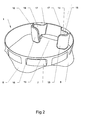
- la figure 2 représente en perspective un dispositif de maintien selon un premier mode d'exécution de l'invention,
- la figure 3 représente en perspective un dispositif de maintien selon un deuxième mode d'exécution de l'invention,
- à l'instar de la figure 1, la figure 4 représente le dispositif de maintien selon un premier mode d'exécution de l'invention, d'une part en position dans le col d'un récipient, et d'autre part maintenant en position verticale l'ustensile,
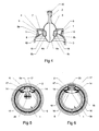
- les figures 5 et 6, en correspondance avec la figure 4, représentent deux positions relatives différentes de l'ustensile par rapport au dispositif de maintien,
- à l'instar de la figure 1, la figure 7 représente un deuxième mode d'exécution d'un dispositif de maintien selon l'invention,
- en correspondance avec la figure 7, les figures 8 et 9 représentent deux positions relatives de l'ustensile par rapport au dispositif de maintien selon figure 7,
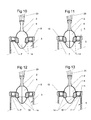
- à l'instar de la figure 1, les figures 10 à 13 représentent respectivement quatre autres modes d'exécution de la présente invention,
- les figures 14 et 15 représentent, en perspective, respectivement en dehors du récipient, et en position dans le récipient, un autre mode d'exécution des moyens de retenue de la coupelle de la cuillère.
- 1 shows in vertical section an assembly consisting of a container, a holding device according to a first embodiment of the invention, and the utensil of the spoon type held in a vertical position by the holding device in the opening of the container,
- FIG. 2 is a perspective view of a holding device according to a first embodiment of the invention,
- FIG. 3 is a perspective view of a holding device according to a second embodiment of the invention;
- as in FIG. 1, FIG. 4 represents the holding device according to a first embodiment of the invention, on the one hand in position in the neck of a container, and on the other hand now in vertical position the utensil,
- FIGS. 5 and 6, in correspondence with FIG. 4, represent two different relative positions of the utensil with respect to the holding device,
- as in FIG. 1, FIG. 7 represents a second embodiment of a holding device according to the invention,
- in correspondence with FIG. 7, FIGS. 8 and 9 represent two relative positions of the utensil with respect to the holding device according to FIG. 7,
- as in FIG. 1, FIGS. 10 to 13 respectively represent four other embodiments of the present invention,
- Figures 14 and 15 show, in perspective, respectively outside the container, and in position in the container, another embodiment of the retaining means of the cup of the spoon.
Comme le montre la figure 1, un dispositif de maintien (1) selon l'invention est agencé pour coopérer, d'un côté avec un récipient (3) adapté pour contenir un aliment liquide ou peu consistant, du type sauce ou confiture, et de l'autre côté avec un ustensile du type cuillère.As shown in Figure 1, a holding device (1) according to the invention is arranged to cooperate on one side with a container (3) adapted to contain a liquid or low food, sauce or jam type, and on the other side with a spoon-type utensil.
De manière générale, et comme considéré et exposé ci-après, le récipient (3) comporte, d'une part un col (5) ménageant une ouverture (4), par exemple respectivement tubulaire et circulaire, et d'autre part un corps (10) de dimensions transversales supérieures à celle du corps (5), en sorte qu'il existe un décrochement (11) reliant le col (5) au corps (10) du récipient. Par ailleurs, mais comme non représenté, le récipient (3) est associé à un moyen de fermeture, du type couvercle, vissable par exemple, comportant le cas échéant un moyen d'étanchéité, du type joint, venant en appui contre la bordure extérieure de l'ouverture (4) ou du col (5) dudit récipient, et par conséquent obturant l'ouverture (4)In general, and as considered and explained below, the container (3) comprises, firstly a neck (5) forming an opening (4), for example respectively tubular and circular, and secondly a body (10) of transverse dimensions greater than that of the body (5), so that there is a recess (11) connecting the neck (5) to the body (10) of the container. Moreover, but not shown, the container (3) is associated with a closure means, of the lid type, screwable for example, optionally comprising a sealing means, of the seal type, bearing against the outer edge the opening (4) or the neck (5) of said container, and therefore closing the opening (4)
Classiquement un ustensile (2) du type cuillère comporte une coupelle (6) ou partie creuse pour le prélèvement de l'aliment contenu dans le récipient au travers de l'ouverture (4). Plus particulièrement, aux fins de la description ci-après, on distingue dans la coupelle (6) une partie distale (6a), délimitée par deux bordures latérales (6b et 6c) convergeant vers l'extrémité distale (6d) de la coupelle, ainsi qu'une surface extrados (6e) de forme généralement convexe, opposée à la surface interne de cette dernière, de forme généralement concave. Bien entendu la géométrie et les dimensions de la coupelle sont adaptées au passage libre de l'ustensile dans l'ouverture et le col du récipient, afin d'y prélever l'aliment contenu.Conventionally a utensil (2) of the spoon type comprises a cup (6) or hollow portion for taking the food contained in the container through the opening (4). More particularly, for the purposes of the following description, there is in the cup (6) a distal portion (6a), delimited by two side edges (6b and 6c) converging towards the distal end (6d) of the cup, and an extrados surface (6e) of generally convex shape, opposite to the internal surface thereof, of generally concave shape. Of course the geometry and dimensions of the cup are adapted to the free passage of the utensil in the opening and the neck of the container, in order to take the food contained.
De manière générale, un dispositif (1) selon l'invention permet le maintien d'un ustensile (2) dans l'ouverture (4) du récipient (3). Et ce dispositif comprend :
- une âme (7) dont le profil, continu ou discontinu, est adapté à son logement à l'intérieur et autour du col (5) du récipient (3) ; en l'occurrence, et à titre d'exemple, l'âme a la forme générale d'un anneau,
- des moyens de solidarisation de cette âme dans le col (5),
- et des moyens de retenue de la coupelle (6) de l'ustensile (2), agencés comme décrit ci-après, pour un maintien dudit ustensile en position verticale dans l'ouverture (4) du récipient (3), ces moyens de retenue saillant à l'intérieur de l'âme annulaire (7).
- a core (7) whose profile, continuous or discontinuous, is adapted to its housing inside and around the neck (5) of the container (3); in this case, and by way of example, the soul has the general shape of a ring,
- means for securing this core in the neck (5),
- and retaining means of the cup (6) of the utensil (2), arranged as described below, for holding said utensil in a vertical position in the opening (4) of the container (3), these means of protruding retainer within the annular core (7).
Selon un mode d'exécution de l'invention, ces moyens de solidarisation de l'âme sont des moyens de serrage axial, élastique, de part et d'autre d'une zone de serrage (5a) du col (5), choisie à cet effet.According to one embodiment of the invention, these means for securing the core are elastic axial clamping means, on either side of a clamping zone (5a) of the neck (5), chosen for this purpose.
Ces moyens de serrage axial comprennent d'une manière générale, du côté intérieur du récipient (3), une ou plusieurs ailes radiales (8) d'appui élastique contre une partie intérieure (5b) du col (5), et du côté extérieur des moyens antagonistes (9) d'appui contre le col (5), mais à l'intérieur de l'ouverture (4).These axial clamping means generally comprise, on the inside of the container (3), one or more radial wings (8) of elastic support against an inner part (5b) of the neck (5), and on the outer side antagonistic means (9) bearing against the neck (5), but inside the opening (4).
Comme montré par les figures 2 et 3, les moyens de solidarisation comprennent plusieurs ailes radiales (8) distribuées autour de l'âme 7.As shown in FIGS. 2 and 3, the securing means comprise several radial wings (8) distributed around the
Comme montré par les figures 4 et 7, chaque aile (8) est agencée pour prendre appui sur le décrochement (11) reliant le col (5) au corps (10) du récipient (3).As shown in Figures 4 and 7, each wing (8) is arranged to bear on the recess (11) connecting the neck (5) to the body (10) of the container (3).
Comme montré par les figures, lorsque le col (5) du récipient a une forme tubulaire ou annulaire, l'âme (7) a précisément la forme d'un anneau, continu ou discontinu.As shown in the figures, when the neck (5) of the container has a tubular or annular shape, the core (7) has the precise shape of a ring, continuous or discontinuous.
En pratique, deux cas de figure peuvent être distingués, selon les modes de réalisation retenus pour le col, en particulier s'agissant de récipients en verre moulé ou soufflé.In practice, two cases can be distinguished, according to the embodiments retained for the neck, in particular with regard to molded or blown glass containers.
Dans un premier cas, le diamètre intérieur du col (5) décroît de l'extérieur vers l'intérieur du récipient (3), en sorte de déterminer une portée interne tronconique, (Cf. figure 4).In a first case, the inside diameter of the neck (5) decreases from the outside to the inside of the container (3), so as to determine a frustoconical internal surface, (see Figure 4).
Dans ce cas, les moyens antagonistes (9) d'appui comprennent une portée externe (12) de diamètre extérieur décroissant du haut vers le bas du récipient, et ayant donc elle aussi une forme tronconique.In this case, the support means (9) support comprise an outer bearing surface (12) of decreasing outer diameter from the top to the bottom of the container, and thus also having a frustoconical shape.
Dans un deuxième cas, le col (5) du récipient (3) détermine une portée interne cylindrique.In a second case, the neck (5) of the container (3) determines a cylindrical internal surface.
Dans ce cas, les moyens antagonistes (9) d'appui comprennent un rebord (13) extérieur tourné vers l'extérieur (Cf. figure 7) dont la forme concave interne est adaptée pour épouser la forme externe convexe, ou rayon, de la bordure intérieure mais tournée vers l'extérieur, délimitant l'ouverture (4) du col (5).In this case, the opposing means (9) support comprise an outer rim (13) facing outward (see Figure 7) whose inner concave shape is adapted to conform to the convex outer shape, or radius, of the inner border but facing outwards, delimiting the opening (4) of the neck (5).
Par conséquent, dans le premier cas, la zone (5a) de serrage retenue sur le col (5) est comprise entre, d'un côté le décrochement (11) du récipient, et de l'autre côté la portée interne tronconique du col, et dans le second cas, entre ce même décrochement et la bordure intérieure, mais tournée vers l'extérieur, délimitant l'ouverture (4) du col (5).Therefore, in the first case, the clamping zone (5a) retained on the neck (5) is between, on one side the recess (11) of the container, and on the other side the frustoconical internal scope of the neck , and in the second case, between the same recess and the inner edge, but facing outwards, delimiting the opening (4) of the neck (5).
Comme montré par les figures 10 à 13, lorsque le col 5 du récipient 3 et le reste de ce dernier déterminent ensemble une seule et même portée cylindrique :
- le profil de l'âme 7 est adapté pour un serrage centrifuge, à l'intérieur du
col 5, par exemple par coincement ou emmanchement dur ; conférer figure 10, - le cas échéant,
l'âme 7 comporte, de manière complémentaire,un rebord 13 intérieur, tourné vers l'extérieur, dont la forme concave est adaptée pour épouser la forme externe convexe de la bordure intérieure délimitant l'ouverture 4du col 5 ; conférer figures 11et 13, - le cas échéant, le dispositif de maintien est réalisé par injection bi-matière, d'une part d'un matériau thermo-plastique, et d'autre part d'un matériau élastomère, et l'âme 7 en ledit matériau thermo-plastique est associée à une ceinture externe 30 en ledit matériau élastomère ; conférer figures 12
et 13.
- the profile of the
core 7 is adapted for centrifugal clamping, inside theneck 5, for example by wedging or hard fitting; confer figure 10, - where appropriate, the
core 7 comprises, in a complementary manner, an outwardly facinginner flange 13, the concave shape of which is adapted to match the convex outer shape of the inner edge delimiting theopening 4 of theneck 5; give figures 11 and 13, - if necessary, the holding device is made by bi-material injection, firstly of a thermoplastic material, and secondly of an elastomeric material, and the
core 7 of said thermoplastic material is associated with anouter belt 30 of said elastomeric material; give figures 12 and 13.
Quelque soit le mode d'exécution retenu pour l'invention, les moyens de retenue du dispositif de maintien comprennent deux mâchoires (14) solidaires de l'âme (7), disposées en vis-à-vis, et agencées, et notamment profilées, pour déterminer entre elles un intervalle de logement (15) de la partie distale (6a) de la coupelle (6) de l'ustensile (2).Whatever the embodiment chosen for the invention, the retaining means of the holding device comprise two jaws (14). integral with the core (7), arranged facing each other, and arranged, and in particular profiled, for determining between them a housing gap (15) of the distal portion (6a) of the cup (6) of the utensil (2).
Les profils internes de cet intervalle, dans différents plans transversaux parallèles respectivement, selon l'axe du col (5), permettent une pénétration de haut en bas de la partie distale (6a) de la coupelle (6), avec blocage de cette dernière à l'intérieur et contre ces mâchoires (14).The internal profiles of this gap, in different parallel transverse planes respectively, along the axis of the neck (5), allow penetration from top to bottom of the distal portion (6a) of the cup (6), with locking of the latter inside and against these jaws (14).
Chaque mâchoire (14) comporte deux mors (16 et 17) en vis-à-vis, délimitant entre eux deux portées d'appui (18), respectivement contre deux bordures latérales (6b et 6c) de la coupelle (6) convergeant l'une vers l'autre à l'extrémité distale (6d) de cette même coupelle. Ces deux portées internes (18) d'appui, en vis-à-vis, convergent l'une vers l'autre, de haut en bas.Each jaw (14) comprises two jaws (16 and 17) facing each other, delimiting between them two bearing surfaces (18), respectively against two lateral edges (6b and 6c) of the cup (6) converging the to one another at the distal end (6d) of the same cup. These two internal bearing surfaces (18), facing each other, converge towards one another, from top to bottom.
Les deux mors (16 et 17) de chaque mâchoire (14) déterminent entre eux un interstice de blocage contre, d'un côté la surface extrados (6e) de la coupelle (6), et de l'autre côté une bordure latérale (6b, 6c) de ladite coupelle (6), ce qui permet comme montré par les figures 5 et 6, et 8 et 9 deux positions de retenue de la coupelle (6), et donc de l'ustensile (2) dans l'ouverture du récipient, à savoir :
- une position représentée aux figures 6
et 8, dans laquelle la surface extrados (6e) de la coupelle (6) est tournée vers l'intérieur du récipient, - et une position montrée aux figures 5
et 9, dans laquelle cette même surface extrados est tournée vers l'extérieur.
- a position shown in Figures 6 and 8, wherein the extrados surface (6e) of the cup (6) is turned towards the inside of the container,
- and a position shown in Figures 5 and 9, wherein the same extrados surface is facing outwards.
Comme montré par les figures 14 et 15, les moyens de retenue de la coupelle de l'ustensile peuvent prendre la forme d'un panier 40, perméable vis-à-vis de l'égouttage dudit ustensile.As shown in Figures 14 and 15, the retaining means of the cup of the utensil can take the form of a
Un dispositif de maintien tel que précédemment décrit apporte au surplus les avantages suivants :
- il supporte l'ustensile entre ces différentes utilisations, dans un emplacement situé dans la partie intérieure haute du récipient, ce qui permet d'éviter à la fois tout écoulement extérieur de l'aliment et l'immersion de l'ustensile dans le récipient,
- il permet l'égouttage libre de l'aliment souillant la coupelle de l'ustensile dans le récipient, et ce sans entrave,
- il maintient fermement l'ustensile en position verticale, ce qui assure sa stabilité lors des déplacements et de l'inclinaison du récipient,
- il ne gène pas la fermeture du récipient, et n'altère pas l'étanchéité originale de ce dernier, par exemple par fermeture avec un couvercle avec joint d'étanchéité contre la bordure de l'ouverture,
- il peut rester en place, ce qui évite toute manipulation ou lavage, indépendant,
- le faible encombrement, et le positionnement de ce dispositif rendent celui-ci très discret ; il n'entrave en rien l'utilisation et l'accessibilité du récipient, vers le produit qui y est contenu.
- it supports the utensil between these different uses, in a location located in the upper inner part of the container, which makes it possible to avoid both any external flow of the food and the immersion of the utensil in the container,
- it allows the free draining of food staining the cup of the utensil in the container, and this without hindrance,
- it holds the utensil firmly in an upright position, which ensures its stability during movement and inclination of the container,
- it does not interfere with the closure of the container, and does not affect the original seal of the latter, for example by closing with a lid with a seal against the edge of the opening,
- it can stay in place, avoiding any manipulation or washing, independent,
- the small size, and the positioning of this device makes it very discreet; it does not hinder the use and accessibility of the container, to the product contained therein.
Pour terminer, un tel dispositif de maintien peut être réalisé de manière monobloc par injection d'une matière plastique appropriée, par exemple à une utilisation alimentaire.Finally, such a holding device can be made in one piece by injection of a suitable plastic material, for example for food use.
Par ailleurs, l'invention concerne aussi un récipient comprenant un col (5) ménageant une ouverture (4), adapté pour contenir un aliment liquide ou peu consistant, caractérisé en ce qu'il est équipé avec un dispositif de maintien (1) d'un ustensile (2) du type cuillère dans son ouverture, tel que décrit précédemment.Furthermore, the invention also relates to a container comprising a neck (5) forming an opening (4), adapted to contain a liquid food or little consistent, characterized in that it is equipped with a holding device (1) d an utensil (2) of the spoon type in its opening, as described above.
Par ailleurs, l'invention concerne aussi un tel récipient, rempli avec un aliment, et éventuellement obturé avec un moyen de fermeture obturant l'ouverture (4).Furthermore, the invention also relates to such a container, filled with a food, and possibly closed with a closing means closing the opening (4).
Claims (16)
Applications Claiming Priority (1)
| Application Number | Priority Date | Filing Date | Title |
|---|---|---|---|
| FR0501212A FR2881634B1 (en) | 2005-02-07 | 2005-02-07 | DEVICE FOR MAINTAINING A SPOIL TYPE UTENSIL IN OPENING A CONTAINER |
Publications (1)
| Publication Number | Publication Date |
|---|---|
| EP1690476A1 true EP1690476A1 (en) | 2006-08-16 |
Family
ID=35094560
Family Applications (1)
| Application Number | Title | Priority Date | Filing Date |
|---|---|---|---|
| EP06002360A Withdrawn EP1690476A1 (en) | 2005-02-07 | 2006-02-06 | Means for supporting an utensil such as a spoon in the opening of a container |
Country Status (2)
| Country | Link |
|---|---|
| EP (1) | EP1690476A1 (en) |
| FR (1) | FR2881634B1 (en) |
Cited By (1)
| Publication number | Priority date | Publication date | Assignee | Title |
|---|---|---|---|---|
| US11647853B1 (en) | 2020-08-11 | 2023-05-16 | Ryan P Newland | Ring for holding knife inside jar |
Citations (5)
| Publication number | Priority date | Publication date | Assignee | Title |
|---|---|---|---|---|
| DE3629718A1 (en) | 1986-09-01 | 1988-03-03 | Johann Friedrich Raab | Wiping-off device and place of deposit for spoons used as utensils for removing viscous masses such as honey, jam and the like from known containers |
| DE3940429A1 (en) * | 1989-12-07 | 1991-06-13 | Johann Friedrich Raab | Spoon holder for packaging container - has arcuate segment fitting on container edge and resiliently adapting to different diameters |
| BE1007748A3 (en) * | 1993-11-29 | 1995-10-10 | Vanhoudt | Aid for use with containers or jars of liquid, semi-liquid and dryfoodstuffs |
| DE19718310A1 (en) * | 1997-04-30 | 1998-11-05 | Butzke Karl Friedrich | Jar clamping insert with resting and supporting rim for spoons etc. |
| DE29817273U1 (en) * | 1998-09-25 | 1998-12-24 | Liedtke Christian | Device for holding a spoon or fork-like removal device during breaks in use |
Family Cites Families (4)
| Publication number | Priority date | Publication date | Assignee | Title |
|---|---|---|---|---|
| US1752522A (en) * | 1929-01-12 | 1930-04-01 | Albert J Eckelman | Spoon-holding clip |
| GB614491A (en) * | 1946-07-16 | 1948-12-16 | Stanley Jardine Smith | Support for spoons or the like for use with jars or other containers |
| FR2574273B3 (en) * | 1984-12-11 | 1987-07-03 | Palau Michel | SPOON HOLDING DEVICE FOR JARS OF FOOD PRODUCTS FOR FRACTIONAL USE |
| DE29602339U1 (en) * | 1996-02-10 | 1996-04-04 | Goeppert Ulrich | Cutlery holder |
-
2005
- 2005-02-07 FR FR0501212A patent/FR2881634B1/en not_active Expired - Fee Related
-
2006
- 2006-02-06 EP EP06002360A patent/EP1690476A1/en not_active Withdrawn
Patent Citations (5)
| Publication number | Priority date | Publication date | Assignee | Title |
|---|---|---|---|---|
| DE3629718A1 (en) | 1986-09-01 | 1988-03-03 | Johann Friedrich Raab | Wiping-off device and place of deposit for spoons used as utensils for removing viscous masses such as honey, jam and the like from known containers |
| DE3940429A1 (en) * | 1989-12-07 | 1991-06-13 | Johann Friedrich Raab | Spoon holder for packaging container - has arcuate segment fitting on container edge and resiliently adapting to different diameters |
| BE1007748A3 (en) * | 1993-11-29 | 1995-10-10 | Vanhoudt | Aid for use with containers or jars of liquid, semi-liquid and dryfoodstuffs |
| DE19718310A1 (en) * | 1997-04-30 | 1998-11-05 | Butzke Karl Friedrich | Jar clamping insert with resting and supporting rim for spoons etc. |
| DE29817273U1 (en) * | 1998-09-25 | 1998-12-24 | Liedtke Christian | Device for holding a spoon or fork-like removal device during breaks in use |
Cited By (1)
| Publication number | Priority date | Publication date | Assignee | Title |
|---|---|---|---|---|
| US11647853B1 (en) | 2020-08-11 | 2023-05-16 | Ryan P Newland | Ring for holding knife inside jar |
Also Published As
| Publication number | Publication date |
|---|---|
| FR2881634A1 (en) | 2006-08-11 |
| FR2881634B1 (en) | 2009-04-17 |
Similar Documents
| Publication | Publication Date | Title |
|---|---|---|
| BE1006495A3 (en) | Closure for container assembly. | |
| EP0839735B1 (en) | Articulated closure cap with improved connecting element | |
| EP0667301B1 (en) | Dispensing device for liquid or powder products | |
| CA2118388C (en) | Dispensing equipment with one way closing element | |
| FR2909544A1 (en) | COOLING DEVICE | |
| FR2891707A1 (en) | Seal for lid of cosmetic product container has two inner lips that converge to grip container ring when pressed in place | |
| FR2979099A1 (en) | PRODUCT DISPENSING HEAD FOR A CONTAINER AND ASSOCIATED DISTRIBUTION DEVICE | |
| EP1868901A1 (en) | Multiple pivoting flask | |
| WO2009019393A2 (en) | Device for cosmetic product including a tank and an applicator | |
| EP1406041A2 (en) | Security device for puncturable cartridge | |
| EP1690476A1 (en) | Means for supporting an utensil such as a spoon in the opening of a container | |
| EP1071477B1 (en) | Device for packaging and treating bactericide for contact lenses | |
| FR2632612A1 (en) | ANTI-FILLING CLOSURE FOR BOTTLES AND CONTAINERS | |
| FR2629996A1 (en) | Screen which can be adapted to a bathtub, incorporating a device for vertical sliding of the walls | |
| FR2774364A1 (en) | CLOSING DEVICE FOR A TIN OF BEVERAGE, ESPECIALLY SOFT DRINK | |
| FR2738897A1 (en) | SET OF A LIQUEFIED, COMPRESSED OR DISSOLVED GAS STORAGE CONTAINER UNDER PRESSURE, PRESSURIZED GAS STORAGE CONTAINER AND HANDLING CAP FOR SUCH CONTAINER | |
| WO2003035273A1 (en) | Fluid dispenser | |
| EP3621893B1 (en) | Spacer ring for positioning between a container and a stopper and assembly of said container and stopper | |
| FR2871442A1 (en) | Cooking device for bottle containing sparking wine or soda, has pumping unit introducing gas within bottle and partly housed within hollow cylindrical body, and corking device partly inserted within bottle | |
| FR2744004A1 (en) | DEVICE FOR GRIPPING AND ATTACHING A COVER, IN PARTICULAR ON A CULINARY CONTAINER | |
| FR3076696A1 (en) | TOWEL SUSPENSION DEVICE for bottle | |
| FR2733487A1 (en) | CLOSING DEVICE FOR A SIDE OPENING OF AN AXIALLY RETRACTABLE DISTRIBUTION, CONTAINER AND METHOD | |
| EP0143704A2 (en) | Pouring device for a container and container provided with such a device | |
| EP4029416A1 (en) | Removable infuser for tea or another plant for infusion capable of and intended for equipping an infuser container and infuser container provided with an infuser | |
| FR2540467A1 (en) | Closure for container with a generous nozzle |
Legal Events
| Date | Code | Title | Description |
|---|---|---|---|
| PUAI | Public reference made under article 153(3) epc to a published international application that has entered the european phase |
Free format text: ORIGINAL CODE: 0009012 |
|
| 17P | Request for examination filed |
Effective date: 20060206 |
|
| AK | Designated contracting states |
Kind code of ref document: A1 Designated state(s): AT BE BG CH CY CZ DE DK EE ES FI FR GB GR HU IE IS IT LI LT LU LV MC NL PL PT RO SE SI SK TR |
|
| AX | Request for extension of the european patent |
Extension state: AL BA HR MK YU |
|
| 17Q | First examination report despatched |
Effective date: 20061011 |
|
| AKX | Designation fees paid |
Designated state(s): AT BE BG CH CY CZ DE DK EE ES FI FR GB GR HU IE IS IT LI LT LU LV MC NL PL PT RO SE SI SK TR |
|
| STAA | Information on the status of an ep patent application or granted ep patent |
Free format text: STATUS: THE APPLICATION IS DEEMED TO BE WITHDRAWN |
|
| 18D | Application deemed to be withdrawn |
Effective date: 20090901 |