EP3669714A1 - Electrically insulated sealed boiler for washing in water - Google Patents
Electrically insulated sealed boiler for washing in water Download PDFInfo
- Publication number
- EP3669714A1 EP3669714A1 EP19214576.1A EP19214576A EP3669714A1 EP 3669714 A1 EP3669714 A1 EP 3669714A1 EP 19214576 A EP19214576 A EP 19214576A EP 3669714 A1 EP3669714 A1 EP 3669714A1
- Authority
- EP
- European Patent Office
- Prior art keywords
- kettle
- external control
- conduit
- control device
- control unit
- Prior art date
- Legal status (The legal status is an assumption and is not a legal conclusion. Google has not performed a legal analysis and makes no representation as to the accuracy of the status listed.)
- Granted
Links
- XLYOFNOQVPJJNP-UHFFFAOYSA-N water Substances O XLYOFNOQVPJJNP-UHFFFAOYSA-N 0.000 title description 8
- 238000005406 washing Methods 0.000 title description 2
- 238000010438 heat treatment Methods 0.000 claims abstract description 16
- 239000000463 material Substances 0.000 claims description 21
- 230000002093 peripheral effect Effects 0.000 claims description 17
- 229920001296 polysiloxane Polymers 0.000 claims description 14
- 238000012360 testing method Methods 0.000 claims description 4
- 238000007789 sealing Methods 0.000 abstract description 10
- 238000010292 electrical insulation Methods 0.000 abstract description 7
- 239000011324 bead Substances 0.000 description 3
- 230000007547 defect Effects 0.000 description 3
- 238000009835 boiling Methods 0.000 description 2
- 230000002950 deficient Effects 0.000 description 2
- 238000009434 installation Methods 0.000 description 2
- 238000003908 quality control method Methods 0.000 description 2
- 206010014405 Electrocution Diseases 0.000 description 1
- 230000004913 activation Effects 0.000 description 1
- 230000015556 catabolic process Effects 0.000 description 1
- 230000000295 complement effect Effects 0.000 description 1
- 238000006731 degradation reaction Methods 0.000 description 1
- 239000013536 elastomeric material Substances 0.000 description 1
- 210000004907 gland Anatomy 0.000 description 1
- 230000007257 malfunction Effects 0.000 description 1
- 238000004519 manufacturing process Methods 0.000 description 1
- 238000000034 method Methods 0.000 description 1
- 238000013021 overheating Methods 0.000 description 1
- 238000003825 pressing Methods 0.000 description 1
- 229920005989 resin Polymers 0.000 description 1
- 239000011347 resin Substances 0.000 description 1
- 230000000284 resting effect Effects 0.000 description 1
- 238000000926 separation method Methods 0.000 description 1
Images


Classifications
-
- A—HUMAN NECESSITIES
- A47—FURNITURE; DOMESTIC ARTICLES OR APPLIANCES; COFFEE MILLS; SPICE MILLS; SUCTION CLEANERS IN GENERAL
- A47J—KITCHEN EQUIPMENT; COFFEE MILLS; SPICE MILLS; APPARATUS FOR MAKING BEVERAGES
- A47J27/00—Cooking-vessels
- A47J27/21—Water-boiling vessels, e.g. kettles
- A47J27/21008—Water-boiling vessels, e.g. kettles electrically heated
- A47J27/2105—Water-boiling vessels, e.g. kettles electrically heated of the cordless type, i.e. whereby the water vessel can be plugged into an electrically-powered base element
-
- A—HUMAN NECESSITIES
- A47—FURNITURE; DOMESTIC ARTICLES OR APPLIANCES; COFFEE MILLS; SPICE MILLS; SUCTION CLEANERS IN GENERAL
- A47J—KITCHEN EQUIPMENT; COFFEE MILLS; SPICE MILLS; APPARATUS FOR MAKING BEVERAGES
- A47J27/00—Cooking-vessels
- A47J27/21—Water-boiling vessels, e.g. kettles
- A47J27/21008—Water-boiling vessels, e.g. kettles electrically heated
-
- A—HUMAN NECESSITIES
- A47—FURNITURE; DOMESTIC ARTICLES OR APPLIANCES; COFFEE MILLS; SPICE MILLS; SUCTION CLEANERS IN GENERAL
- A47J—KITCHEN EQUIPMENT; COFFEE MILLS; SPICE MILLS; APPARATUS FOR MAKING BEVERAGES
- A47J27/00—Cooking-vessels
- A47J27/21—Water-boiling vessels, e.g. kettles
- A47J27/21166—Constructional details or accessories
- A47J27/21175—Covers
-
- A—HUMAN NECESSITIES
- A47—FURNITURE; DOMESTIC ARTICLES OR APPLIANCES; COFFEE MILLS; SPICE MILLS; SUCTION CLEANERS IN GENERAL
- A47J—KITCHEN EQUIPMENT; COFFEE MILLS; SPICE MILLS; APPARATUS FOR MAKING BEVERAGES
- A47J36/00—Parts, details or accessories of cooking-vessels
- A47J36/02—Selection of specific materials, e.g. heavy bottoms with copper inlay or with insulating inlay
- A47J36/04—Selection of specific materials, e.g. heavy bottoms with copper inlay or with insulating inlay the materials being non-metallic
Definitions
- the present invention relates to an electric kettle and aims to improve the sealing and the electrical insulation of the kettle in order to be able to wash it completely under water, without impairing the proper functioning of the appliance and without danger of electric shock to the 'user.
- a kettle which comprises a body, a heating plate, a lower housing in which is housed an internal control device and sealing means implemented between the body, the heating plate and the lower housing.
- This kettle has a control switch arranged in a sealed manner on the lower case.
- the control switch is located in a lower part of the kettle, which makes it difficult to access for the user who, moreover, must actuate said button by a horizontal press. Thus, such a kettle is not ergonomic.
- This kettle comprises a body provided with a handle, a hot plate, a sealed lower case in which is housed an internal control device for the hot plate and a sealed external control box arranged on the handle.
- the external control unit includes an external control device electrically connected by at least one cable to the internal control device and configured to manually actuate said internal control device. Sealing means are provided between the lower housing and the cable, on the one hand, and between the control unit and the cable, on the other hand, these sealing means being implemented by cable glands or resin or silicone overmoldings on the ends of the cable.
- the kettle is subjected to a tightness test before being put into service which, according to this implementation, requires checking the tightness at the level of the lower casing, on the one hand, and at the level of the control casing. , on the other hand, which increases the quality control costs of such a kettle.
- the invention overcomes the aforementioned drawbacks by using a kettle which comprises a body provided with a handle, a hot plate, a sealed lower case in which is housed an internal control device designed to control the hot plate.
- the kettle also comprises a sealed external control unit arranged on the handle, said external control unit comprising an external control device electrically connected by at least one cable to the internal control device and configured to manually actuate said internal control device.
- the lower unit is connected to the external control unit in a leaktight manner by an electrically insulating conduit in which the at least one cable is arranged, the lower unit, the control unit and the conduit forming a sealed area.
- the seal between the cable and the lower box, on the one hand, and between the cable and the control box, on the other hand, is preserved despite the possible disassembly and reassembly between said elements, thanks to the presence of the conduit which receives the cable and which sealingly connects the lower housing and the control unit to form the sealed zone.
- the kettle remains suitably electrically insulated, including when the cable sheath is damaged and the conductive core of said cable is visible.
- the creation of this watertight zone allows the realization of a single leak test for the whole, which reduces the quality control costs of the kettle.
- the internal control device comprises a non-isolated electrical supply.
- a non-isolated electrical supply can be, by way of nonlimiting example, a capacitive supply, a resistive supply or a switching supply of the BUCK or BOOST type.
- the use of a non-isolated electrical supply is made possible by the constitution of the sealed zone ensuring the electrical insulation of the kettle.
- the internal control device would include an isolated electrical supply, which would however increase the cost of manufacturing the kettle.
- the duct is made of a flexible material, in particular silicone.
- a flexible material in particular silicone.
- the use of other flexible materials is possible, as well as the use of rigid material.
- the advantage of a flexible conduit rather than a rigid conduit is however to be able to bend it easily to give it a shape corresponding to that of the handle in order to place it therein.
- Another advantage of a flexible conduit, in particular made of silicone is that this flexibility contributes to the sealing between the conduit and the lower housing, on the one hand, and between the conduit and the external control unit, on the other hand . Indeed, it is thus possible to fit the pipe tightly and tightly onto an end piece of the lower housing and onto a end piece of the external control unit.
- the duct has a diameter greater than 3 mm, preferably greater than 5 mm. This avoids overheating of the cable and facilitates its installation and removal from the conduit, in particular in the presence of connectors at the ends of the cable for the connection of said ends to the external control device and to the internal control device.
- the external control unit comprises a tubular protuberance to which the duct is tightly connected.
- a rigid connection element is arranged between the tubular protuberance and the conduit, but one could provide a direct connection between the tubular protuberance and the conduit, according to another alternative embodiment.
- the external control device comprises an operating member and a switch, the external control unit comprising a flexible wall arranged between the operating member and the switch.
- the external control unit comprises a flexible body.
- the flexible body has a through opening provided with a peripheral lip.
- the external control unit comprises a frame and a closing cover, the peripheral lip being pinched between the cover and the frame to make the flexible body watertight.
- the internal control device comprises a temperature sensor arranged under the hot plate. Said heating plate participates in the watertight closure of the upper part of the lower case. Thus, the temperature sensor allows to measure the temperature inside the lower case.
- the lower housing has an orifice intended for testing the tightness of the lower housing and of the control unit connected by the conduit, the orifice being closed sealingly by a plug.
- the kettle has a lower cover which is arranged on the lower case, the lower cover holding the plug on the orifice.
- the kettle 1 comprises a plastic body 2 which provides very low thermal conduction in order to prevent the user from being burned when handling the kettle containing boiling water.
- a handle 3 fixed to the body 2.
- the body 2 comprises an external peripheral wall 4, preferably of circular shape, which extends vertically when the kettle 1 rests on a plane horizontal working, and the upper part 4a includes a pouring spout 5 for pouring boiling water when the body 2 is inclined.
- This upper part 4a comprises an opening 6 which removably receives a closing cover 75 (illustrated on the figure 5 ).
- the kettle 1 comprises a lower housing 7 also in a plastic material ensuring low thermal conduction.
- This lower housing 7 comprises a container 8 provided with a peripheral wall 9 and a bottom 10.
- the peripheral wall 9 has a shape similar to the external wall 4 of the body 2, in this case a circular shape, and comes lodge in the lower part 4b of the external wall 4.
- This peripheral wall 9 extends upwards and comprises an upper part 9a.
- the kettle 1 comprises a heating plate 11 which has very good thermal conduction and constitutes the bottom of a chamber 12 making it possible to contain water in the body 2 in order to boil it.
- the heating plate 11 includes a peripheral flange 13 similar in shape to the peripheral wall 9 and to the external wall 4, in this case circular in shape.
- This rim 13 includes an internal edge 14 and an external edge 15, of circular shape, which are both curved downwards extending over a length making it possible to receive the upper part 9a of the peripheral wall 9, between said internal 14 and external 15 edges, by means of an internal seal 16 having an annular shape.
- This internal seal 16 assembles and seals between the rim 13 of the heating plate 11 and the upper part 9a of the peripheral wall 9 of the lower housing 7.
- the external edge 15 of the rim 13 comprises at its lower end an external shoulder 17 which extends radially to the periphery of the heating plate 11.
- the lower part 4b of the external wall 4 of the body 2 comprises on one side internal 20 an internal shoulder 18 arranged so that it is disposed above this external shoulder 17 when the internal housing 7 and the heating plate 11 are in position in the body 2.
- an external seal 19 of annular shape ensures a tight and sealed assembly between said external edge 15 and said internal face 20.
- the presence of the external shoulder 17 and the internal shoulder 18 delimit the stop positions of the external seal 19 on said outer edge 15 and on said inner face 20.
- the implementation of this seal between the body 2, the lower housing 7 and the heating plate 11 by means of the internal seal 16 and the external seal 19, makes it possible to define an interior chamber 21 that is sealed which allows in particular the housing of a heating resistor 22 fixed under the heating plate 11, an internal control device 23 and a temperature sensor 24 also fixed under the heating plate 11 and making it possible to measure the temperature of this chamber interior 21.
- the lower housing 7 comprises a female electrical connector 25, arranged in a sealed manner in the bottom 10 of said lower housing 7.
- This electrical connector 25 is connected to the internal control device 23 and allows its electrical connection to a base 26 which comprises a male electrical connector 27 complementary to the female electrical connector 25.
- This base 26 is configured to be electrically connected to an external electrical source by through a power outlet (not shown).
- the design of the external seal 19 differs from that of the figure 1 , the principle however remaining the same.
- the lower case 7 has a shape slightly different from that of the figure 1 and has additional technical characteristics relating to the invention, as will appear in the following description.
- the handle 3 of the kettle 1 consists of a first part 3a completely integrated into the body 2, and a second removable part 3b.
- the second part 3b includes fixing lugs 28 ( figures 1 and 2 ) which cooperate with the first part 3a of this handle 3.
- This first part 3a of the handle 3 comprises an internal recess 29.
- a sealed external control unit 30 is arranged in the upper part of the handle 3 and allows activation of the device internal control 23 housed in the lower housing 7.
- the internal recess 29 on the first part 3a of the handle 3 allows the housing and the passage of a conduit 31.
- the conduit 31 has a diameter of three millimeters (3 mm), preferably five millimeters (5 mm) , the internal recess 29 being dimensioned accordingly.
- This duct 31 is made of a flexible material, preferably silicone, which makes it possible to give it a shape similar to that of the internal recess 29 in which said conduit 31 is housed. It would be possible to use a rigid conduit 31 having a shape identical to that of the internal recess 29.
- the use of this silicone material also provides electrical insulation to the conduit 31 and contributes to sealing for the connection. from the lower case 7 to the sealed external control box 30, as will appear in the following description.
- the lower housing 7 comprises a tip 32 which extends radially with respect to a lower part 9b of the peripheral wall 9.
- the lower end 31a of the conduit 31 passes through the lower part 4b of the wall external 4 of the body 2 and is positioned outside the lower housing 7.
- the lower end 31a of the conduit 31 is mounted clamped by fitting on this end piece 32, which ensures a seal between the lower housing 7 and the conduit 31 of the made use of a silicone material.
- beads 33a, 33b ensuring a tightening of the lower end 31a of the conduit 31 which is fitted onto the end piece 32, or even a clamp (not illustrated).
- the lower box 7 communicates in leaktight manner with the conduit 31, which allows the passage of a cable 74 in the said conduit 31 for its connection to the internal control device 23 housed inside the said lower housing 7.
- the sealed external control box 30 comprises an external control device 33 which comprises a frame 34, a body 35 and a cover 36.
- the frame 34 and the cover 36 are made of a rigid material, preferably a plastic material, and the body 35 is designed in a flexible material, preferably a silicone material.
- the external control device 33 also includes a printed circuit board 37, a cover 38 and an operating member 39.
- the printed circuit board 37 incorporates an on / off switch 40, of the ON / OFF switch type, and a connection pin 41 which extends longitudinally with respect to an edge 42 on said printed circuit board 37.
- the cover 36 defines a first chamber 43 open at its upper part 43a and dimensioned to receive the printed circuit board 37, only the connection pin 41 passing through a contour wall 44 of said cover 36.
- the cover 38 defines a second chamber 45 open at its lower part 45a and dimensioned to also receive the printed circuit board 37 and to be housed in the first chamber 43 by closing the upper part 43a of said first chamber 43, the lower part 45a of the second chamber 45 bearing against a bottom 46 of said cover 36.
- the cover 38 has a bottom 47 which closes said upper part 43a and has a through hole 48 in which a button 49 of the on / off switch 40 is positioned.
- connection pin 41 of the printed circuit board 37 also passes through a contour wall 50 of said cover 38.
- the printed circuit board 37 comprises a light-emitting diode (not shown) which, preferably, lights up in white when the button 49 is pressed.
- the cover 38 is made of a material having a colored tint, for example a blue or red tint, the lighting of the light-emitting diode associated with the tint of the cover 38 giving a luminous background of the color of said cover 38, that the user visualizes by switching on the kettle 1.
- the body 35 is hollow and provided with an opening 51 delimited by a peripheral lip 52 on its lower wall 53, thus allowing access to the interior of said body 35 and to accommodate there the pre-assembled assembly formed by the cover 36 , of the printed circuit board 37 and of the cover 38, as explained previously and as illustrated on the figure 4 .
- the button 49 of the on / off switch 40 is in contact with the underside of the upper wall 54 of the body 35.
- the connection pin 41 passes through a contour wall 55 of the body 35 , tightly and tightly thanks to the use of a silicone material.
- a tubular protrusion 56 also made of silicone material, preferably forms a single piece with the body 35 and laterally extends the contour wall 55 of said body 35, the connection pin 41 being housed in this tubular protrusion 56, like the illustrate the figures 4 and 5 .
- the assembly thus produced and illustrated in particular in figure 4 allows physical separation between the body 35 of silicone material and the printed circuit board 37, which advantageously ensures that the material silicone of said body 35 does not charge electrically and, thus, protects against electrostatic discharges.
- the frame 34 is hollow and dimensioned to receive the pre-assembled assembly formed by the cover 36, the printed circuit board 37, the cover 38 and the body 35, as explained above and as illustrated in the figures 4 and 5 .
- the tubular protuberance 56 passes through a contour wall 57 of said frame 34, with the connection pin 41 housed in said tubular protrusion 56.
- the peripheral lip 52 of the flexible body 35 is sandwiched between the bottom 46 of the cover 36 and a bottom 58 of said chassis 34, these two bottoms 46, 58 being fixed together by fixing screws 59 (illustrated in figure 2 ), this screwing between said bottoms 46, 58 making it possible to pinch the peripheral lip 52 of the body 35 and to ensure a seal of the external control device 33.
- the fixing screws 59 pass through the bottom 58 of the chassis 34 and come in taken in non-opening threads (not shown) in the bottom 46 of the cover 36, so as not to compromise the tightness of the external control device 33.
- the operating member 39 is mounted on the chassis 34 and has a stud 76 disposed in contact with the top of the upper wall 54 of the body 35, in alignment with the button 49 of the on / off switch 40.
- the operating member 39 comprises a pusher 60 which can be pressed with a finger of the user, pressing the pusher 60 enabling the pad 76 to be pressed in and deforming the upper wall 54 of the body 35, which enables said button 49 of the on / off switch 40 to be actuated.
- a connection element 61 has the form of a tubular end piece 62 made of a rigid material, in particular a plastic material, the two end portions 62a, 62b of this tubular end piece 62 comprising external beads 63, 64.
- This end piece tubular 62 is dimensioned to be force fitted, on one side, in the tubular protrusion 56 and, on the other side, in the upper end 31b of the conduit 31.
- the flexibility of the silicone material used for the conduit 31 and the tubular protrusion 56 and the presence of the external beads 63, 64 on the rigid tubular endpiece 62 make it possible to ensure a tight connection between the upper end 31b of the duct 31, the connection element 61 and the external control unit 30.
- Circular stops 65, 66 on the tubular endpiece 62 delimit the stop positions of the upper end 31b of the duct and tubular protuberance 56 which are fitted onto said tubular end-piece 62.
- the end 41a of the connection pin 41 of the printed circuit board 37 is housed in the tubular protrusion 56, near the tubular end-piece 62, as illustrate them figures 4 and 5 . This makes it possible to electrically connect, with a perfect seal, the end of a cable 74 passing through the conduit 31, with the connection pin 41 of the printed circuit board 37, said cable 74 having its second end connected to the internal control 23 in the lower housing 7.
- connection pin 41 with the cable 74 is preferably made by a connector (not illustrated) which is connected to the end of said cable 74 and which removably plugs into said connection pin 41. This facilitates disassembly between the conduit 31, the cable 74 and the external control unit 30, in the event of a defect in a component of said external control unit 30.
- the assembly forms a completely sealed zone, owing to the fact that the lower casing 7 is mounted in leaktight manner with the body 2 of the kettle 1, as explained above, and that the external control box 30 is in itself watertight by its aforementioned design.
- This sealed zone is thus electrically insulated, which advantageously allows the use of a non-insulated electrical supply on the internal control device 23 in the lower housing 7, without any risk of electrocution during the handling of the kettle 1 and of the operating member 39.
- the chassis 34 of the external control device 33 is housed in the internal recess 29 of the first part 3a of the handle 3 and fixed inside this recess 29 by means of fixing screws 67 (illustrated in figure 2 ).
- the second part 3b of the handle 3 comprises an opening 68 which allows the passage of the pusher 60 of the operating member 39, during its assembly with the first part 3a of the handle.
- the flexibility of the conduit 31 which is tightly connected to the external control unit 30, allows its deformation in order to place it suitably in the internal recess 29 of the first part 3a of the handle before the installation of the second part 3b of this handle 3.
- the tightness of the assembly consisting of the lower housing 7, the conduit 31 and the external control unit 30, forming said sealed zone, can be checked by virtue of the presence of an orifice 69 arranged on the bottom 10 of the container 8 of the lower case 7, as illustrated in figure 3 , which makes it possible to inject pressurized air and to check for possible leaks on said assembly, before placing the kettle on the market 1.
- this orifice 69 is closed in leaktight manner by a plug 70, illustrated in figure 2 , made of elastomeric material. Maintaining the plug 70 in position is guaranteed by the presence of a lower cover 71 which is fixed with the bottom 10 of said container 8 by means of fixing screws 72, said lower cover 71 being further assembled with the lower end. 2a of the body 2 thanks to assembly tabs 73.
Landscapes
- Engineering & Computer Science (AREA)
- Food Science & Technology (AREA)
- Cookers (AREA)
Abstract
L'invention concerne une bouilloire (1) disposant d'une étanchéité et d'une isolation électrique optimisées. La bouilloire comprend un corps (2) muni d'une poignée (3), une plaque chauffante (11), un boîtier inférieur (7) étanche dans lequel est logé un dispositif de commande interne (23) et un boitier de commande externe (30) étanche agencé sur la poignée. Le boitier de commande externe comporte un dispositif de commande externe (33) relié électriquement par au moins un câble au dispositif de commande interne et configuré pour actionner manuellement ledit dispositif de commande interne. Le boitier inférieur (7) est relié au boitier de commande externe (30) de manière étanche par un conduit (31) électriquement isolant dans lequel est agencé l'au moins un câble, le boitier inférieur, le boitier de commande et le conduit formant une zone étanche.The invention relates to a kettle (1) having optimized sealing and electrical insulation. The kettle comprises a body (2) provided with a handle (3), a heating plate (11), a sealed lower case (7) in which is housed an internal control device (23) and an external control box ( 30) waterproof arranged on the handle. The external control unit includes an external control device (33) electrically connected by at least one cable to the internal control device and configured to manually actuate said internal control device. The lower box (7) is connected to the external control box (30) in a leaktight manner by an electrically insulating conduit (31) in which the at least one cable is arranged, the lower box, the control box and the conduit forming a sealed area.
Description
La présente invention concerne une bouilloire électrique et vise à améliorer l'étanchéité et l'isolation électrique de la bouilloire afin de pouvoir la laver complètement sous l'eau, sans nuire au bon fonctionnement de l'appareil et sans danger d'électrocution pour l'utilisateur.The present invention relates to an electric kettle and aims to improve the sealing and the electrical insulation of the kettle in order to be able to wash it completely under water, without impairing the proper functioning of the appliance and without danger of electric shock to the 'user.
Diverses conceptions de bouilloires étanches sont connues de l'homme du métier. A titre d'exemple, la demande internationale de brevet publiée sous le numéro
La demande de brevet chinoise publiée sous le numéro
La demanderesse a déjà pallié les divers inconvénients précités en développant une bouilloire présentant les perfectionnements objets des brevets européens
Bien que cette conception de bouilloire selon
L'invention pallie les inconvénients précités en mettant en oeuvre une bouilloire qui comprend un corps muni d'une poignée, une plaque chauffante, un boîtier inférieur étanche dans lequel est logé un dispositif de commande interne conçu pour commander la plaque chauffante. La bouilloire comprend également un boitier de commande externe étanche agencé sur la poignée, ledit boitier de commande externe comportant un dispositif de commande externe relié électriquement par au moins un câble au dispositif de commande interne et configuré pour actionner manuellement ledit dispositif de commande interne. En outre, le boitier inférieur est relié au boitier de commande externe de manière étanche par un conduit électriquement isolant dans lequel est agencé l'au moins un câble, le boitier inférieur, le boitier de commande et le conduit formant une zone étanche.The invention overcomes the aforementioned drawbacks by using a kettle which comprises a body provided with a handle, a hot plate, a sealed lower case in which is housed an internal control device designed to control the hot plate. The kettle also comprises a sealed external control unit arranged on the handle, said external control unit comprising an external control device electrically connected by at least one cable to the internal control device and configured to manually actuate said internal control device. In addition, the lower unit is connected to the external control unit in a leaktight manner by an electrically insulating conduit in which the at least one cable is arranged, the lower unit, the control unit and the conduit forming a sealed area.
Ainsi, l'étanchéité entre le câble et le boîtier inférieur, d'une part, et entre le câble et le boîtier de commande, d'autre part, est préservé malgré les démontages et remontages éventuels entre lesdits éléments, grâce à la présence du conduit qui reçoit le câble et qui raccorde de manière étanche le boîtier inférieur et le boîtier de commande pour former la zone étanche. En outre, la bouilloire reste convenablement isolée électriquement, y compris lorsque la gaine du câble est abimée et que l'âme conductrice dudit câble est apparente. Par ailleurs, la création de cette zone étanche permet la réalisation d'un seul test d'étanchéité pour l'ensemble, ce qui réduit les coûts de contrôle qualité de la bouilloire.Thus, the seal between the cable and the lower box, on the one hand, and between the cable and the control box, on the other hand, is preserved despite the possible disassembly and reassembly between said elements, thanks to the presence of the conduit which receives the cable and which sealingly connects the lower housing and the control unit to form the sealed zone. In addition, the kettle remains suitably electrically insulated, including when the cable sheath is damaged and the conductive core of said cable is visible. In addition, the creation of this watertight zone allows the realization of a single leak test for the whole, which reduces the quality control costs of the kettle.
Selon une réalisation de la bouilloire, le dispositif de commande interne comporte une alimentation électrique non isolée. Une telle alimentation électrique non isolée peut être, à titre d'exemple non limitatif, une alimentation capacitive, une alimentation résistive ou une alimentation à découpage de type BUCK ou BOOST. L'utilisation d'une alimentation électrique non isolée est rendue possible grâce à la constitution de la zone étanche assurant l'isolation électrique de la bouilloire. Bien entendu, il serait possible de prévoir des variantes de réalisation de la bouilloire selon l'invention pour lesquelles le dispositif de commande interne comporterait une alimentation électrique isolée, ce qui augmenterait cependant le coût de fabrication de la bouilloire.According to an embodiment of the kettle, the internal control device comprises a non-isolated electrical supply. Such a non-isolated electrical supply can be, by way of nonlimiting example, a capacitive supply, a resistive supply or a switching supply of the BUCK or BOOST type. The use of a non-isolated electrical supply is made possible by the constitution of the sealed zone ensuring the electrical insulation of the kettle. Of course, it would be possible to provide alternative embodiments of the kettle according to the invention for which the internal control device would include an isolated electrical supply, which would however increase the cost of manufacturing the kettle.
Selon une réalisation de la bouilloire, le conduit est réalisé en une matière souple, notamment en silicone. L'utilisation d'autres matières souples est envisageable, de même que l'utilisation de matière rigide. L'avantage d'un conduit souple plutôt que d'un conduit rigide est toutefois de pouvoir le courber facilement pour lui donner une forme correspondant à celle de la poignée afin de le placer dans celle-ci. Un autre avantage d'un conduit souple, notamment en silicone, est que cette souplesse participe à l'étanchéité entre le conduit et le boîtier inférieur, d'une part, et entre le conduit et le boîtier de commande externe, d'autre part. En effet, il est ainsi possible d'emboîter de manière serrée et étanche le conduit sur un embout du boîtier inférieur et sur un embout du boîtier de commande externe.According to one embodiment of the kettle, the duct is made of a flexible material, in particular silicone. The use of other flexible materials is possible, as well as the use of rigid material. The advantage of a flexible conduit rather than a rigid conduit is however to be able to bend it easily to give it a shape corresponding to that of the handle in order to place it therein. Another advantage of a flexible conduit, in particular made of silicone, is that this flexibility contributes to the sealing between the conduit and the lower housing, on the one hand, and between the conduit and the external control unit, on the other hand . Indeed, it is thus possible to fit the pipe tightly and tightly onto an end piece of the lower housing and onto a end piece of the external control unit.
Selon une réalisation de la bouilloire, le conduit présente un diamètre supérieur à 3 mm, de préférence supérieur à 5 mm. Cela évite les échauffements du câble et facilite sa mise en place et son retrait du conduit, en particulier en la présence de connecteurs aux extrémités du câble pour le raccordement desdites extrémités au dispositif de commande externe et au dispositif de commande interne.According to one embodiment of the kettle, the duct has a diameter greater than 3 mm, preferably greater than 5 mm. This avoids overheating of the cable and facilitates its installation and removal from the conduit, in particular in the presence of connectors at the ends of the cable for the connection of said ends to the external control device and to the internal control device.
Selon une réalisation de la bouilloire, le boitier de commande externe comporte une excroissance tubulaire sur laquelle le conduit est connecté de manière étanche. De préférence, un élément de connexion rigide est agencé entre l'excroissance tubulaire et le conduit, mais on pourrait prévoir une connexion directe entre l'excroissance tubulaire et le conduit, selon une autre variante de réalisation.According to one embodiment of the kettle, the external control unit comprises a tubular protuberance to which the duct is tightly connected. Preferably, a rigid connection element is arranged between the tubular protuberance and the conduit, but one could provide a direct connection between the tubular protuberance and the conduit, according to another alternative embodiment.
Selon une réalisation de la bouilloire, le dispositif de commande externe comporte un organe de manœuvre et un interrupteur, le boitier de commande externe comportant une paroi souple agencée entre l'organe de manœuvre et l'interrupteur.According to one embodiment of the kettle, the external control device comprises an operating member and a switch, the external control unit comprising a flexible wall arranged between the operating member and the switch.
Selon une réalisation de la bouilloire, le boitier de commande externe comporte un corps souple. En outre, le corps souple comporte une ouverture traversante munie d'une lèvre périphérique. En outre, le boitier de commande externe comporte un châssis et un couvercle de fermeture, la lèvre périphérique étant pincée entre le couvercle et le châssis pour rendre le corps souple étanche. Selon une réalisation de la bouilloire, le dispositif de commande interne comporte un capteur de température agencé sous la plaque chauffante. Ladite plaque chauffante participe à la fermeture étanche de la partie supérieure du boitier inférieur. Ainsi, le capteur de température permet de mesurer la température à l'intérieur du boitier inférieur.According to one embodiment of the kettle, the external control unit comprises a flexible body. In addition, the flexible body has a through opening provided with a peripheral lip. In addition, the external control unit comprises a frame and a closing cover, the peripheral lip being pinched between the cover and the frame to make the flexible body watertight. According to an embodiment of the kettle, the internal control device comprises a temperature sensor arranged under the hot plate. Said heating plate participates in the watertight closure of the upper part of the lower case. Thus, the temperature sensor allows to measure the temperature inside the lower case.
Selon une réalisation de la bouilloire, le boîtier inférieur comporte un orifice destiné à tester l'étanchéité du boîtier inférieur et du boitier de commande reliés par le conduit, l'orifice étant fermé étanchement par un bouchon.According to one embodiment of the kettle, the lower housing has an orifice intended for testing the tightness of the lower housing and of the control unit connected by the conduit, the orifice being closed sealingly by a plug.
Selon une réalisation de la bouilloire, celle-ci comporte un couvercle inférieur qui est agencé sur le boitier inférieur, le couvercle inférieur maintenant le bouchon sur l'orifice.According to an embodiment of the kettle, it has a lower cover which is arranged on the lower case, the lower cover holding the plug on the orifice.
Les caractéristiques et avantages de l'invention apparaîtront à la lecture de la description suivante s'appuyant sur des figures, parmi lesquelles :
- [
Fig. 1 ] Lafigure 1 est une vue d'une bouilloire selon l'art antérieur, dont une grande partie des caractéristiques techniques s'applique à la bouilloire objet de l'invention ; - [
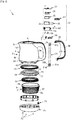
Fig. 2 ] Lafigure 2 est une vue éclatée mettant en évidence, notamment, le boîtier inférieur et le boîtier de commande externe de la bouilloire objet de l'invention ; - [
Fig. 3 ] Lafigure 3 est une vue montrant de dessous le boîtier inférieur ; - [
Fig. 4 ] Lafigure 4 est une vue montrant en coupe le boîtier de commande externe. - [
Fig. 5 ] lafigure 5 est une vue en coupe d'une bouilloire selon l'invention, montrant notamment le conduit reliant le boîtier inférieur au boîtier de commande.
- [
Fig. 1 ] Thefigure 1 is a view of a kettle according to the prior art, a large part of the technical characteristics of which applies to the kettle which is the subject of the invention; - [
Fig. 2 ] Thefigure 2 is an exploded view showing, in particular, the lower housing and the external control unit of the kettle object of the invention; - [
Fig. 3 ] Thefigure 3 is a view showing from below the lower case; - [
Fig. 4 ] Thefigure 4 is a view showing in section the external control unit. - [
Fig. 5 ] thefigure 5 is a sectional view of a kettle according to the invention, showing in particular the conduit connecting the lower housing to the control unit.
Dans la suite de la description, les mêmes références sont utilisées pour décrire les mêmes caractéristiques ou leurs équivalents selon les diverses conceptions possibles de la bouilloire selon l'invention.In the following description, the same references are used to describe the same characteristics or their equivalents according to the various possible designs of the kettle according to the invention.
Dans la suite de la description, les termes tels que « haut », « bas », « inférieur », « supérieur », « vertical », « horizontal » ... seront utilisés en considération de la position normale de la bouilloire reposant sur un plan de travail horizontal.In the following description, terms such as "top", "bottom", "bottom", "top", "vertical", "horizontal" ... will be used in consideration of the normal position of the kettle resting on a horizontal work plan.
Sur la
Sur la
Tel qu'illustré sur la
Tel qu'illustré sur la
Tel qu'illustré sur la
Tel qu'illustré en
L'homme du métier pourra se référer au brevet
En regard des
La description qui suit va maintenant s'attacher à décrire plus précisément les caractéristiques techniques propres à l'invention, à l'appui des
Tel qu'illustré sur les
Tel qu'illustré en regard des
Tel qu'illustré en regard des
Tel qu'illustré en regard des
Tel qu'illustré en regard des
Tel qu'illustré en regard des
Une fois l'extrémité inférieure 31a du conduit 31 raccordée de manière étanche avec l'embout 32 du boîtier inférieur 7 d'une part et l'extrémité supérieure 31b du conduit 31 raccordée de manière étanche avec le boîtier de commande externe 30 d'autre part, l'ensemble forme une zone complètement étanche, du fait que le boîtier inférieur 7 est monté de manière étanche avec le corps 2 de la bouilloire 1, comme expliqué précédemment, et que le boîtier de commande externe 30 est en lui-même étanche de par sa conception précitée. Cette zone étanche est ainsi isolée électriquement, ce qui permet avantageusement l'utilisation d'une alimentation électrique non isolée sur le dispositif de commande interne 23 dans le boîtier inférieur 7, sans aucun risque d'électrocution durant la manipulation de la bouilloire 1 et de l'organe de manœuvre 39.Once the
Le châssis 34 du dispositif de commande externe 33 est logé dans l'évidement interne 29 de la première partie 3a de la poignée 3 et fixé à l'intérieur de cet évidement 29 au moyen de vis de fixation 67 (illustrées en
L'étanchéité de l'ensemble constitué du boîtier inférieur 7, du conduit 31 et du boîtier de commande externe 30, formant ladite zone étanche, peut être contrôlée grâce à la présence d'un orifice 69 agencé sur le fond 10 du contenant 8 du boîtier inférieur 7, tel qu'illustré en
D'autres caractéristiques sont envisageables dans le cadre de l'invention. On peut prévoir des variantes de conception de l'étanchéité entre le boîtier inférieur 7 et le corps 2 de la bouilloire 1, et aussi prévoir des variantes de conception du boîtier de commande externe 30, tout en conservant la constitution de la zone étanche entre le boîtier inférieur 7, le conduit 31 et le boîtier de commande externe 30 pour le raccordement électrique du dispositif de commande interne 23 disposé dans le boîtier inférieur 7 au dispositif de commande externe 33 disposé dans le boîtier de commande externe 30, au moyen d'un câble logé dans ledit conduit 31.Other characteristics can be envisaged in the context of the invention. It is possible to provide design variants of the seal between the
Claims (14)
Applications Claiming Priority (1)
| Application Number | Priority Date | Filing Date | Title |
|---|---|---|---|
| FR1873081A FR3089776B1 (en) | 2018-12-17 | 2018-12-17 | ELECTRICALLY INSULATED SEALED KETTLE FOR WASHING UNDER WATER |
Publications (2)
| Publication Number | Publication Date |
|---|---|
| EP3669714A1 true EP3669714A1 (en) | 2020-06-24 |
| EP3669714B1 EP3669714B1 (en) | 2021-11-03 |
Family
ID=66530232
Family Applications (1)
| Application Number | Title | Priority Date | Filing Date |
|---|---|---|---|
| EP19214576.1A Active EP3669714B1 (en) | 2018-12-17 | 2019-12-09 | Electrically insulated sealed boiler for washing in water |
Country Status (4)
| Country | Link |
|---|---|
| EP (1) | EP3669714B1 (en) |
| JP (1) | JP7323429B2 (en) |
| CN (2) | CN211511451U (en) |
| FR (1) | FR3089776B1 (en) |
Families Citing this family (1)
| Publication number | Priority date | Publication date | Assignee | Title |
|---|---|---|---|---|
| FR3089776B1 (en) * | 2018-12-17 | 2020-11-20 | Seb Sa | ELECTRICALLY INSULATED SEALED KETTLE FOR WASHING UNDER WATER |
Citations (6)
| Publication number | Priority date | Publication date | Assignee | Title |
|---|---|---|---|---|
| GB2249472A (en) * | 1988-03-10 | 1992-05-13 | Haden D H Ltd | Electric kettles |
| CN201213711Y (en) | 2008-05-30 | 2009-04-01 | 广东德豪润达电气股份有限公司 | Wireless electric heating kettle |
| WO2009109762A1 (en) | 2008-03-07 | 2009-09-11 | Otter Controls Limited | Electrical appliances and components |
| US20100314379A1 (en) * | 2009-06-10 | 2010-12-16 | Lin Hsi-Mei | Temperature control device for vehicle thermal cup |
| EP2805649A1 (en) * | 2013-05-21 | 2014-11-26 | Seb S.A. | Boiler comprising a sealed control module |
| EP2805650B1 (en) | 2013-05-21 | 2016-03-16 | Seb S.A. | Boiler comprising a sealed housing |
Family Cites Families (12)
| Publication number | Priority date | Publication date | Assignee | Title |
|---|---|---|---|---|
| JPS6142249U (en) * | 1984-08-21 | 1986-03-18 | マツダ株式会社 | Waterproofing device for machine tool motors |
| JP5009044B2 (en) * | 2007-05-16 | 2012-08-22 | 象印マホービン株式会社 | Electric pot |
| CN201058138Y (en) * | 2007-06-18 | 2008-05-14 | 邓以翔 | Water oxygen champignon machine |
| JP5239354B2 (en) * | 2008-01-23 | 2013-07-17 | タイガー魔法瓶株式会社 | Electric kettle |
| CN201987340U (en) * | 2011-01-20 | 2011-09-28 | 佛山市顺德区建丰行贸易有限公司 | Double-layer heat-insulating container used in coffee maker and tea boiling machine |
| GB2517485A (en) * | 2013-08-22 | 2015-02-25 | Otter Controls Ltd | Appliances and components therefor |
| CN204146859U (en) * | 2014-11-10 | 2015-02-11 | 佛山市汇莱德电器有限公司 | The electric kettle of water on a kind of handle |
| CN205125939U (en) * | 2015-10-29 | 2016-04-06 | 叶元奖 | Energy -conserving insulating pot of safe type |
| JP6142249B2 (en) | 2016-03-08 | 2017-06-07 | 株式会社高尾 | Circulating game machine |
| KR20180015438A (en) * | 2016-08-03 | 2018-02-13 | 김광엽 | The water separation cover |
| CN207005939U (en) * | 2017-08-10 | 2018-02-13 | 任乔岳 | A kind of heat sinking Waterproof LED Down lamp |
| FR3089776B1 (en) * | 2018-12-17 | 2020-11-20 | Seb Sa | ELECTRICALLY INSULATED SEALED KETTLE FOR WASHING UNDER WATER |
-
2018
- 2018-12-17 FR FR1873081A patent/FR3089776B1/en active Active
-
2019
- 2019-11-06 JP JP2019201531A patent/JP7323429B2/en active Active
- 2019-12-09 EP EP19214576.1A patent/EP3669714B1/en active Active
- 2019-12-13 CN CN201922233273.1U patent/CN211511451U/en active Active
- 2019-12-13 CN CN201911280062.1A patent/CN111317361B/en active Active
Patent Citations (7)
| Publication number | Priority date | Publication date | Assignee | Title |
|---|---|---|---|---|
| GB2249472A (en) * | 1988-03-10 | 1992-05-13 | Haden D H Ltd | Electric kettles |
| WO2009109762A1 (en) | 2008-03-07 | 2009-09-11 | Otter Controls Limited | Electrical appliances and components |
| CN201213711Y (en) | 2008-05-30 | 2009-04-01 | 广东德豪润达电气股份有限公司 | Wireless electric heating kettle |
| US20100314379A1 (en) * | 2009-06-10 | 2010-12-16 | Lin Hsi-Mei | Temperature control device for vehicle thermal cup |
| EP2805649A1 (en) * | 2013-05-21 | 2014-11-26 | Seb S.A. | Boiler comprising a sealed control module |
| EP2805650B1 (en) | 2013-05-21 | 2016-03-16 | Seb S.A. | Boiler comprising a sealed housing |
| EP2805649B1 (en) | 2013-05-21 | 2018-05-02 | Seb S.A. | Boiler comprising a sealed control module |
Also Published As
| Publication number | Publication date |
|---|---|
| CN111317361B (en) | 2022-12-20 |
| EP3669714B1 (en) | 2021-11-03 |
| FR3089776B1 (en) | 2020-11-20 |
| JP2020096818A (en) | 2020-06-25 |
| CN211511451U (en) | 2020-09-18 |
| CN111317361A (en) | 2020-06-23 |
| FR3089776A1 (en) | 2020-06-19 |
| JP7323429B2 (en) | 2023-08-08 |
Similar Documents
| Publication | Publication Date | Title |
|---|---|---|
| EP2805649B1 (en) | Boiler comprising a sealed control module | |
| EP2805650B1 (en) | Boiler comprising a sealed housing | |
| EP2005869B1 (en) | Cooking appliance comprising a safety system | |
| FR2882434A3 (en) | INDUCTIVE PRESSURE SENSOR, ESPECIALLY FOR HOUSEHOLD APPLIANCES, BOILERS AND OTHER | |
| FR2975882A1 (en) | SAFETY VALVE FOR PRESSURIZED COOKING APPARATUS AND DEVICE INCLUDING SUCH A VALVE | |
| EP3669714B1 (en) | Electrically insulated sealed boiler for washing in water | |
| FR2889890A3 (en) | COVER FOR A CONNECTING DEVICE | |
| EP3088599B1 (en) | Household ironing appliance comprising a steam generator provided with a discharge opening | |
| EP1848066A2 (en) | Secured watertight electrical connection device | |
| EP1192888B1 (en) | Removable water reservoir, in particular for a steam cooking device | |
| EP1117318B1 (en) | Electrical appliance for heating liquids, comprising a heating base and glass walls | |
| FR2710790A1 (en) | Sealed feedthrough (penetration) device | |
| EP2915928B1 (en) | Detachable siphon | |
| EP4065907B1 (en) | Tank of liquid able to be heated | |
| FR3070404B1 (en) | IRONING APPARATUS COMPRISING A BASE CONNECTED BY A CORD TO AN IRON | |
| FR3070403B1 (en) | IRON CONTAINING AN ELECTRIC RESISTANCE AND A FUSE FOR CUTTING THE POWER SUPPLY OF THE ELECTRICAL RESISTANCE | |
| EP0712450B1 (en) | Steam iron | |
| FR3070405B1 (en) | IRON CONTAINING AN HOUSING, A HEATING BODY AND A FUNCTIONAL PLATINUM INTERPOSED BETWEEN THE HEATING BODY AND THE HOUSING | |
| EP2103238B1 (en) | Cooking device cover comprising a dual-wall window | |
| WO2003032795A1 (en) | Cooking appliance with a vessel comprising a draining device with a filter | |
| EP2782845B1 (en) | Closure device for a refillable diffuser housing and diffuser housing comprising same | |
| FR2868882A1 (en) | ELECTRICAL CONNECTION DEVICE SEALED | |
| EP3524107A1 (en) | Kitchen appliance comprising a drainage core controlled by a hydraulic control | |
| FR2781313A1 (en) | Air evacuation arrangement for electrical connector assembly uses sealing strip with flexible upper sides to allow trapped air to escape from inside the connector during insertion coupling movement | |
| FR2728450A3 (en) | APPARATUS FOR HEATING LIQUIDS |
Legal Events
| Date | Code | Title | Description |
|---|---|---|---|
| PUAI | Public reference made under article 153(3) epc to a published international application that has entered the european phase |
Free format text: ORIGINAL CODE: 0009012 |
|
| STAA | Information on the status of an ep patent application or granted ep patent |
Free format text: STATUS: THE APPLICATION HAS BEEN PUBLISHED |
|
| AK | Designated contracting states |
Kind code of ref document: A1 Designated state(s): AL AT BE BG CH CY CZ DE DK EE ES FI FR GB GR HR HU IE IS IT LI LT LU LV MC MK MT NL NO PL PT RO RS SE SI SK SM TR |
|
| AX | Request for extension of the european patent |
Extension state: BA ME |
|
| STAA | Information on the status of an ep patent application or granted ep patent |
Free format text: STATUS: REQUEST FOR EXAMINATION WAS MADE |
|
| 17P | Request for examination filed |
Effective date: 20201116 |
|
| RBV | Designated contracting states (corrected) |
Designated state(s): AL AT BE BG CH CY CZ DE DK EE ES FI FR GB GR HR HU IE IS IT LI LT LU LV MC MK MT NL NO PL PT RO RS SE SI SK SM TR |
|
| STAA | Information on the status of an ep patent application or granted ep patent |
Free format text: STATUS: EXAMINATION IS IN PROGRESS |
|
| 17Q | First examination report despatched |
Effective date: 20210430 |
|
| GRAP | Despatch of communication of intention to grant a patent |
Free format text: ORIGINAL CODE: EPIDOSNIGR1 |
|
| STAA | Information on the status of an ep patent application or granted ep patent |
Free format text: STATUS: GRANT OF PATENT IS INTENDED |
|
| INTG | Intention to grant announced |
Effective date: 20210625 |
|
| GRAS | Grant fee paid |
Free format text: ORIGINAL CODE: EPIDOSNIGR3 |
|
| GRAA | (expected) grant |
Free format text: ORIGINAL CODE: 0009210 |
|
| STAA | Information on the status of an ep patent application or granted ep patent |
Free format text: STATUS: THE PATENT HAS BEEN GRANTED |
|
| AK | Designated contracting states |
Kind code of ref document: B1 Designated state(s): AL AT BE BG CH CY CZ DE DK EE ES FI FR GB GR HR HU IE IS IT LI LT LU LV MC MK MT NL NO PL PT RO RS SE SI SK SM TR |
|
| REG | Reference to a national code |
Ref country code: GB Ref legal event code: FG4D Free format text: NOT ENGLISH |
|
| REG | Reference to a national code |
Ref country code: AT Ref legal event code: REF Ref document number: 1443203 Country of ref document: AT Kind code of ref document: T Effective date: 20211115 Ref country code: CH Ref legal event code: EP |
|
| REG | Reference to a national code |
Ref country code: IE Ref legal event code: FG4D Free format text: LANGUAGE OF EP DOCUMENT: FRENCH |
|
| REG | Reference to a national code |
Ref country code: DE Ref legal event code: R096 Ref document number: 602019008942 Country of ref document: DE |
|
| REG | Reference to a national code |
Ref country code: LT Ref legal event code: MG9D |
|
| REG | Reference to a national code |
Ref country code: NL Ref legal event code: MP Effective date: 20211103 |
|
| REG | Reference to a national code |
Ref country code: AT Ref legal event code: MK05 Ref document number: 1443203 Country of ref document: AT Kind code of ref document: T Effective date: 20211103 |
|
| PG25 | Lapsed in a contracting state [announced via postgrant information from national office to epo] |
Ref country code: RS Free format text: LAPSE BECAUSE OF FAILURE TO SUBMIT A TRANSLATION OF THE DESCRIPTION OR TO PAY THE FEE WITHIN THE PRESCRIBED TIME-LIMIT Effective date: 20211103 Ref country code: LT Free format text: LAPSE BECAUSE OF FAILURE TO SUBMIT A TRANSLATION OF THE DESCRIPTION OR TO PAY THE FEE WITHIN THE PRESCRIBED TIME-LIMIT Effective date: 20211103 Ref country code: FI Free format text: LAPSE BECAUSE OF FAILURE TO SUBMIT A TRANSLATION OF THE DESCRIPTION OR TO PAY THE FEE WITHIN THE PRESCRIBED TIME-LIMIT Effective date: 20211103 Ref country code: BG Free format text: LAPSE BECAUSE OF FAILURE TO SUBMIT A TRANSLATION OF THE DESCRIPTION OR TO PAY THE FEE WITHIN THE PRESCRIBED TIME-LIMIT Effective date: 20220203 Ref country code: AT Free format text: LAPSE BECAUSE OF FAILURE TO SUBMIT A TRANSLATION OF THE DESCRIPTION OR TO PAY THE FEE WITHIN THE PRESCRIBED TIME-LIMIT Effective date: 20211103 |
|
| PG25 | Lapsed in a contracting state [announced via postgrant information from national office to epo] |
Ref country code: IS Free format text: LAPSE BECAUSE OF FAILURE TO SUBMIT A TRANSLATION OF THE DESCRIPTION OR TO PAY THE FEE WITHIN THE PRESCRIBED TIME-LIMIT Effective date: 20220303 Ref country code: SE Free format text: LAPSE BECAUSE OF FAILURE TO SUBMIT A TRANSLATION OF THE DESCRIPTION OR TO PAY THE FEE WITHIN THE PRESCRIBED TIME-LIMIT Effective date: 20211103 Ref country code: PT Free format text: LAPSE BECAUSE OF FAILURE TO SUBMIT A TRANSLATION OF THE DESCRIPTION OR TO PAY THE FEE WITHIN THE PRESCRIBED TIME-LIMIT Effective date: 20220303 Ref country code: PL Free format text: LAPSE BECAUSE OF FAILURE TO SUBMIT A TRANSLATION OF THE DESCRIPTION OR TO PAY THE FEE WITHIN THE PRESCRIBED TIME-LIMIT Effective date: 20211103 Ref country code: NO Free format text: LAPSE BECAUSE OF FAILURE TO SUBMIT A TRANSLATION OF THE DESCRIPTION OR TO PAY THE FEE WITHIN THE PRESCRIBED TIME-LIMIT Effective date: 20220203 Ref country code: NL Free format text: LAPSE BECAUSE OF FAILURE TO SUBMIT A TRANSLATION OF THE DESCRIPTION OR TO PAY THE FEE WITHIN THE PRESCRIBED TIME-LIMIT Effective date: 20211103 Ref country code: LV Free format text: LAPSE BECAUSE OF FAILURE TO SUBMIT A TRANSLATION OF THE DESCRIPTION OR TO PAY THE FEE WITHIN THE PRESCRIBED TIME-LIMIT Effective date: 20211103 Ref country code: HR Free format text: LAPSE BECAUSE OF FAILURE TO SUBMIT A TRANSLATION OF THE DESCRIPTION OR TO PAY THE FEE WITHIN THE PRESCRIBED TIME-LIMIT Effective date: 20211103 Ref country code: GR Free format text: LAPSE BECAUSE OF FAILURE TO SUBMIT A TRANSLATION OF THE DESCRIPTION OR TO PAY THE FEE WITHIN THE PRESCRIBED TIME-LIMIT Effective date: 20220204 Ref country code: ES Free format text: LAPSE BECAUSE OF FAILURE TO SUBMIT A TRANSLATION OF THE DESCRIPTION OR TO PAY THE FEE WITHIN THE PRESCRIBED TIME-LIMIT Effective date: 20211103 |
|
| PG25 | Lapsed in a contracting state [announced via postgrant information from national office to epo] |
Ref country code: SM Free format text: LAPSE BECAUSE OF FAILURE TO SUBMIT A TRANSLATION OF THE DESCRIPTION OR TO PAY THE FEE WITHIN THE PRESCRIBED TIME-LIMIT Effective date: 20211103 Ref country code: SK Free format text: LAPSE BECAUSE OF FAILURE TO SUBMIT A TRANSLATION OF THE DESCRIPTION OR TO PAY THE FEE WITHIN THE PRESCRIBED TIME-LIMIT Effective date: 20211103 Ref country code: RO Free format text: LAPSE BECAUSE OF FAILURE TO SUBMIT A TRANSLATION OF THE DESCRIPTION OR TO PAY THE FEE WITHIN THE PRESCRIBED TIME-LIMIT Effective date: 20211103 Ref country code: EE Free format text: LAPSE BECAUSE OF FAILURE TO SUBMIT A TRANSLATION OF THE DESCRIPTION OR TO PAY THE FEE WITHIN THE PRESCRIBED TIME-LIMIT Effective date: 20211103 Ref country code: DK Free format text: LAPSE BECAUSE OF FAILURE TO SUBMIT A TRANSLATION OF THE DESCRIPTION OR TO PAY THE FEE WITHIN THE PRESCRIBED TIME-LIMIT Effective date: 20211103 Ref country code: CZ Free format text: LAPSE BECAUSE OF FAILURE TO SUBMIT A TRANSLATION OF THE DESCRIPTION OR TO PAY THE FEE WITHIN THE PRESCRIBED TIME-LIMIT Effective date: 20211103 |
|
| REG | Reference to a national code |
Ref country code: DE Ref legal event code: R097 Ref document number: 602019008942 Country of ref document: DE |
|
| PG25 | Lapsed in a contracting state [announced via postgrant information from national office to epo] |
Ref country code: MC Free format text: LAPSE BECAUSE OF FAILURE TO SUBMIT A TRANSLATION OF THE DESCRIPTION OR TO PAY THE FEE WITHIN THE PRESCRIBED TIME-LIMIT Effective date: 20211103 |
|
| PLBE | No opposition filed within time limit |
Free format text: ORIGINAL CODE: 0009261 |
|
| STAA | Information on the status of an ep patent application or granted ep patent |
Free format text: STATUS: NO OPPOSITION FILED WITHIN TIME LIMIT |
|
| REG | Reference to a national code |
Ref country code: BE Ref legal event code: MM Effective date: 20211231 |
|
| 26N | No opposition filed |
Effective date: 20220804 |
|
| PG25 | Lapsed in a contracting state [announced via postgrant information from national office to epo] |
Ref country code: LU Free format text: LAPSE BECAUSE OF NON-PAYMENT OF DUE FEES Effective date: 20211209 Ref country code: IE Free format text: LAPSE BECAUSE OF NON-PAYMENT OF DUE FEES Effective date: 20211209 Ref country code: AL Free format text: LAPSE BECAUSE OF FAILURE TO SUBMIT A TRANSLATION OF THE DESCRIPTION OR TO PAY THE FEE WITHIN THE PRESCRIBED TIME-LIMIT Effective date: 20211103 |
|
| PG25 | Lapsed in a contracting state [announced via postgrant information from national office to epo] |
Ref country code: SI Free format text: LAPSE BECAUSE OF FAILURE TO SUBMIT A TRANSLATION OF THE DESCRIPTION OR TO PAY THE FEE WITHIN THE PRESCRIBED TIME-LIMIT Effective date: 20211103 Ref country code: BE Free format text: LAPSE BECAUSE OF NON-PAYMENT OF DUE FEES Effective date: 20211231 |
|
| PG25 | Lapsed in a contracting state [announced via postgrant information from national office to epo] |
Ref country code: IT Free format text: LAPSE BECAUSE OF FAILURE TO SUBMIT A TRANSLATION OF THE DESCRIPTION OR TO PAY THE FEE WITHIN THE PRESCRIBED TIME-LIMIT Effective date: 20211103 |
|
| PG25 | Lapsed in a contracting state [announced via postgrant information from national office to epo] |
Ref country code: CY Free format text: LAPSE BECAUSE OF FAILURE TO SUBMIT A TRANSLATION OF THE DESCRIPTION OR TO PAY THE FEE WITHIN THE PRESCRIBED TIME-LIMIT Effective date: 20211103 |
|
| PG25 | Lapsed in a contracting state [announced via postgrant information from national office to epo] |
Ref country code: HU Free format text: LAPSE BECAUSE OF FAILURE TO SUBMIT A TRANSLATION OF THE DESCRIPTION OR TO PAY THE FEE WITHIN THE PRESCRIBED TIME-LIMIT; INVALID AB INITIO Effective date: 20191209 |
|
| REG | Reference to a national code |
Ref country code: CH Ref legal event code: PL |
|
| PG25 | Lapsed in a contracting state [announced via postgrant information from national office to epo] |
Ref country code: LI Free format text: LAPSE BECAUSE OF NON-PAYMENT OF DUE FEES Effective date: 20221231 Ref country code: CH Free format text: LAPSE BECAUSE OF NON-PAYMENT OF DUE FEES Effective date: 20221231 |
|
| PGFP | Annual fee paid to national office [announced via postgrant information from national office to epo] |
Ref country code: GB Payment date: 20231221 Year of fee payment: 5 |
|
| PGFP | Annual fee paid to national office [announced via postgrant information from national office to epo] |
Ref country code: FR Payment date: 20231220 Year of fee payment: 5 Ref country code: DE Payment date: 20231208 Year of fee payment: 5 |
|
| PG25 | Lapsed in a contracting state [announced via postgrant information from national office to epo] |
Ref country code: MK Free format text: LAPSE BECAUSE OF FAILURE TO SUBMIT A TRANSLATION OF THE DESCRIPTION OR TO PAY THE FEE WITHIN THE PRESCRIBED TIME-LIMIT Effective date: 20211103 |
|
| PG25 | Lapsed in a contracting state [announced via postgrant information from national office to epo] |
Ref country code: TR Free format text: LAPSE BECAUSE OF FAILURE TO SUBMIT A TRANSLATION OF THE DESCRIPTION OR TO PAY THE FEE WITHIN THE PRESCRIBED TIME-LIMIT Effective date: 20211103 |
|
| PG25 | Lapsed in a contracting state [announced via postgrant information from national office to epo] |
Ref country code: MT Free format text: LAPSE BECAUSE OF FAILURE TO SUBMIT A TRANSLATION OF THE DESCRIPTION OR TO PAY THE FEE WITHIN THE PRESCRIBED TIME-LIMIT Effective date: 20211103 |