EP0806812B1 - Connecteur à ressort pour conducteur électrique ayant des nervures de butée - Google Patents
Connecteur à ressort pour conducteur électrique ayant des nervures de butée Download PDFInfo
- Publication number
- EP0806812B1 EP0806812B1 EP97106686A EP97106686A EP0806812B1 EP 0806812 B1 EP0806812 B1 EP 0806812B1 EP 97106686 A EP97106686 A EP 97106686A EP 97106686 A EP97106686 A EP 97106686A EP 0806812 B1 EP0806812 B1 EP 0806812B1
- Authority
- EP
- European Patent Office
- Prior art keywords
- tension spring
- abutment elements
- housing
- recesses
- Prior art date
- Legal status (The legal status is an assumption and is not a legal conclusion. Google has not performed a legal analysis and makes no representation as to the accuracy of the status listed.)
- Expired - Lifetime
Links
- 239000004020 conductor Substances 0.000 title claims abstract description 16
- 238000003780 insertion Methods 0.000 claims abstract description 18
- 230000037431 insertion Effects 0.000 claims abstract description 18
- 239000002184 metal Substances 0.000 abstract description 2
- 239000000463 material Substances 0.000 abstract 1
- 210000002414 leg Anatomy 0.000 description 16
- 241000722921 Tulipa gesneriana Species 0.000 description 3
- 238000010276 construction Methods 0.000 description 3
- 238000005452 bending Methods 0.000 description 2
- 238000009434 installation Methods 0.000 description 2
- 229910000639 Spring steel Inorganic materials 0.000 description 1
- 238000010521 absorption reaction Methods 0.000 description 1
- 230000006735 deficit Effects 0.000 description 1
- 238000006073 displacement reaction Methods 0.000 description 1
- 238000005516 engineering process Methods 0.000 description 1
- 238000002347 injection Methods 0.000 description 1
- 239000007924 injection Substances 0.000 description 1
- 238000004519 manufacturing process Methods 0.000 description 1
- 230000013011 mating Effects 0.000 description 1
- 238000000034 method Methods 0.000 description 1
- 230000000284 resting effect Effects 0.000 description 1
- 238000007493 shaping process Methods 0.000 description 1
- 239000000243 solution Substances 0.000 description 1
- 210000000689 upper leg Anatomy 0.000 description 1
Images

Classifications
-
- H—ELECTRICITY
- H01—ELECTRIC ELEMENTS
- H01R—ELECTRICALLY-CONDUCTIVE CONNECTIONS; STRUCTURAL ASSOCIATIONS OF A PLURALITY OF MUTUALLY-INSULATED ELECTRICAL CONNECTING ELEMENTS; COUPLING DEVICES; CURRENT COLLECTORS
- H01R4/00—Electrically-conductive connections between two or more conductive members in direct contact, i.e. touching one another; Means for effecting or maintaining such contact; Electrically-conductive connections having two or more spaced connecting locations for conductors and using contact members penetrating insulation
- H01R4/28—Clamped connections, spring connections
- H01R4/48—Clamped connections, spring connections utilising a spring, clip, or other resilient member
- H01R4/4809—Clamped connections, spring connections utilising a spring, clip, or other resilient member using a leaf spring to bias the conductor toward the busbar
- H01R4/4811—Spring details
- H01R4/4816—Spring details the spring shape preventing insertion of the conductor end when the spring is unbiased
-
- H—ELECTRICITY
- H01—ELECTRIC ELEMENTS
- H01R—ELECTRICALLY-CONDUCTIVE CONNECTIONS; STRUCTURAL ASSOCIATIONS OF A PLURALITY OF MUTUALLY-INSULATED ELECTRICAL CONNECTING ELEMENTS; COUPLING DEVICES; CURRENT COLLECTORS
- H01R4/00—Electrically-conductive connections between two or more conductive members in direct contact, i.e. touching one another; Means for effecting or maintaining such contact; Electrically-conductive connections having two or more spaced connecting locations for conductors and using contact members penetrating insulation
- H01R4/28—Clamped connections, spring connections
- H01R4/48—Clamped connections, spring connections utilising a spring, clip, or other resilient member
- H01R4/4809—Clamped connections, spring connections utilising a spring, clip, or other resilient member using a leaf spring to bias the conductor toward the busbar
- H01R4/484—Spring housing details
- H01R4/4844—Spring housing details the spring housing being provided with multiple openings for insertion of a spring-activating tool
Definitions
- Tension spring connections of this type are known in their construction and are commercially available. For such tension spring connections, it is of great importance when operating the Tension spring for inserting a conductor to ensure that the Tension spring does not exceed permissible values and due to plastic deformation the tension spring does not deteriorate. This is the mainspring supported in their position on the conductor rail so that when they are actuated, in particular during their opening movement, an overextension of the spring is prevented.
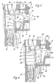
- the insertion opening 9 is above the tension spring 1 in the housing Pocket 4 indicated, through which the tension spring 1 in the direction of assembly direction 7 in the housing pocket 4 can be inserted.
- the Tension spring 1 is provided with recesses 2 and relative to stop elements 3 is arranged, also fixed to the housing in the lower region of the housing pocket 4 are shown in principle.
- the tension spring 1 is in its lower end
- the area assigned to the housing pocket 4 has been provided with recesses 2 in such a way that that the recesses 2 release 1 space in the inserted position of the tension spring for the stop elements 3, which are arranged on the front of the tension spring 1 Walls of the housing pocket 4 are formed.
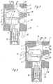
- the movable leg of the tension spring 1 has more Sections 18 which, when this leg is deformed, correspond to the associated Surfaces of the stop elements 3 can, as in FIG. 4, otherwise is identical to FIG. 3.
- the permissible pivoted position of the freely movable Leg of the tension spring 1 results in a more or less flat Contact between the more ready sections 18 of the movable leg of the Tension spring 1 and the contact surfaces of the stop elements 3. This is a inadmissible actuation of the free leg of the tension spring 1 in the direction of the actuation directions 8 safely prevented.
- FIGS. 5 and 6 show a connection element analogous to FIGS. 4 and 5, the undeformed position in FIG. 5 and the deformed position in FIG. 6 the tension spring 1 is indicated.
- the connection element of Figures 5 and 6 acts it is a connection element with an actuation primarily in accordance Figure 5 horizontal direction according to arrow VIII.
- This results in constructive Changes in the busbar 11 and of housing components in this context are not important.
- the dimensional design of the stop elements 3 which due to the assembly of the Tension spring 1 in the direction of the mounting direction 7 not so far into that of the tension spring 1 enclosed interior protrude and therefore, as can be seen in Figure 6, a not so clearly large support of the movable leg of the tension spring 1 allow.
- Through constructive measures, especially the shape of the Busbar 11 and the tension spring 1 can also the stop element 3 according to figures 5 and 6 varies and there is greater coverage between the wider ones Sections 18 of the tension spring 1 and the stop elements 3 can be reached.
Landscapes
- Multi-Conductor Connections (AREA)
- Details Of Connecting Devices For Male And Female Coupling (AREA)
- Connector Housings Or Holding Contact Members (AREA)
- Connections Arranged To Contact A Plurality Of Conductors (AREA)
- Window Of Vehicle (AREA)
Claims (9)
- Connexion à ressort de traction pour conducteurs électriques, notamment dans un boítier à pôles fixes, comportant un ressort de traction (1) plié approximativement en forme de boucle, dont une zone terminale forme une branche destinée à reposer sur un rail électrique (11) et dont l'autre zone terminale forme une branche orientée approximativement perpendiculairement au rail électrique (11), dans laquelle se trouve une fenêtre (10) pour le passage du rail électrique (11), dont le bord inférieur forme un bord de serrage pour le serrage d'un conducteur sous le rail électrique (11), ainsi que des éléments de butée (3) qui coopèrent avec le ressort de traction (1), pour délimiter la course du ressort de traction (1) lorsque celui-ci est actionné,
caractérisée en ce que
le ressort de traction (1) est enfiché dans une poche (4) formée par le boítier (19) et comporte des portions de plus petite largeur, comportant des évidements (2) proches des bords, dans lesquels s'engagent des deux côtés des éléments de butée (3) solidaires de la poche, qui dépassent chacun dans l'espace délimité par le ressort de traction (1) et en ce que le ressort de traction (1) peut s'appliquer, lorsqu'il est actionné, contre les éléments de butée (3), par des portions (18) de plus grande largeur. - Connexion à ressort de traction selon la revendication 1, caractérisée en ce que les évidements (2) proches des bords sont disposés dans la zone du ressort de traction (1) qui pénètre en premier, lors de l'enfichage, dans la poche (4) solidaire du boítier.
- Connexion à ressort de raction selon l'une des revendications 1 ou 2, caractérisée en ce que la forme et l'orientation des évidements (2) peuvent être conçues en fonction du sens d'enfichage (7) du ressort de traction (1) dans la poche de boítier (4).
- Connexion à ressort de traction selon la revendication 1, caractérisée en ce que les portions pus larges (18) du ressort de traction (1), qui peuvent s'appliquer contre les éléments de butée (3), sont disposées au voisinage des évidements (2) proches des bords.
- Connexion à ressort de traction, selon l'une des revendications précédentes, caractérisée en ce que les éléments de butée (3) s'étendent dans le sens d'enfichage (7) du ressort de traction (1) suffisamment loin pour qu'une butée s'établisse entre des portions plus larges (18) du ressort de traction (1) et des éléments de butée (3), de préférence dans la zone bombée (17) du ressort de traction (1).
- Connexion à ressort de traction selon l'une des revendications précédentes, caractérisée en ce que les éléments de butée (3) s'étendent dans le sens d'enfichage (7) du ressort de traction (1), suffisamment loin pour qu'une butée s'établisse entre des portions plus larges (18) du ressort de traction (1) et des éléments de butée (3), juste au-dessus de l'extrémité de la zone des rayons (21) du ressort de traction (1).
- Connexion à ressort de traction selon l'une des revendications précédentes, caractérisée en ce que les bords de contact des éléments de butée (3) sont disposés dans la poche de boítier (4) de manière qu'en butée il s'établisse un contact à plat entre des éléments de butée (3) et des portions plus larges (18) du ressort de traction (1).
- Connexion à ressort de traction selon la revendication 1, caractérisée en ce que les éléments de butée (3) solidaires de la poche ne dépassent qu'un peu dans l'espace enfermé par le ressort de traction (1), en particulier de quelques dixièmes de millimètre seulement.
- Connexion à ressort ce traction selon la revendication 1, caractérisée en ce que les évidements (2) positionnent le ressort de traction (1), en coopération avec les éléments de butée (3), lors de l'enfichage dans la poche de boítier (4).
Applications Claiming Priority (2)
| Application Number | Priority Date | Filing Date | Title |
|---|---|---|---|
| DE29608176U | 1996-05-06 | ||
| DE29608176U DE29608176U1 (de) | 1996-05-06 | 1996-05-06 | Zugfederanschluß für elektrische Leiter mit Anschlagrippen |
Publications (3)
| Publication Number | Publication Date |
|---|---|
| EP0806812A2 EP0806812A2 (fr) | 1997-11-12 |
| EP0806812A3 EP0806812A3 (fr) | 1998-09-30 |
| EP0806812B1 true EP0806812B1 (fr) | 2001-10-04 |
Family
ID=8023590
Family Applications (1)
| Application Number | Title | Priority Date | Filing Date |
|---|---|---|---|
| EP97106686A Expired - Lifetime EP0806812B1 (fr) | 1996-05-06 | 1997-04-23 | Connecteur à ressort pour conducteur électrique ayant des nervures de butée |
Country Status (4)
| Country | Link |
|---|---|
| EP (1) | EP0806812B1 (fr) |
| AT (1) | ATE206562T1 (fr) |
| DE (2) | DE29608176U1 (fr) |
| ES (1) | ES2163059T3 (fr) |
Cited By (2)
| Publication number | Priority date | Publication date | Assignee | Title |
|---|---|---|---|---|
| DE10214919A1 (de) * | 2002-04-04 | 2003-11-27 | Siemens Ag | Zugfederanschluss für elektrische Leiter |
| DE202013105944U1 (de) | 2013-12-26 | 2014-01-22 | Wago Verwaltungsgesellschaft Mbh | Federkraft-Klemmanschluss und Steckverbinder hiermit |
Families Citing this family (4)
| Publication number | Priority date | Publication date | Assignee | Title |
|---|---|---|---|---|
| DE20120811U1 (de) * | 2001-12-21 | 2003-04-30 | Weidmüller Interface GmbH & Co., 32760 Detmold | Sammelschienen-Anschlußklemme |
| DE102006006051B4 (de) * | 2006-02-09 | 2015-10-29 | Wöhner GmbH & Co. KG Elektrotechnische Systeme | Sicherungsleiste mit seitlichen Abgangskontakten |
| DE102006006050B4 (de) * | 2006-02-09 | 2016-07-28 | Wöhner GmbH & Co. KG Elektrotechnische Systeme | Sicherungsleiste sowie Adapterleiste mit Kontaktstiften und der Sicherungsleiste |
| US7561018B2 (en) | 2006-02-09 | 2009-07-14 | Wöhner GmbH & Co. KG | Fuse strip with lateral outgoing contacts and a lateral adapter module |
Family Cites Families (4)
| Publication number | Priority date | Publication date | Assignee | Title |
|---|---|---|---|---|
| GB9311559D0 (en) * | 1993-06-04 | 1993-07-21 | Amp Gmbh | Spring clamp actuator |
| DE4319018C1 (de) * | 1993-06-08 | 1994-06-30 | Kostal Leopold Gmbh & Co Kg | Schraubenlose Anschlußklemmenanordnung |
| DE4413611A1 (de) * | 1994-04-19 | 1995-10-26 | Thomas & Betts Gmbh | Elektrischer Stecker für Flachbandleitungen |
| DE4435781A1 (de) * | 1994-10-06 | 1996-04-11 | Siemens Ag | Federkraftklemme |
-
1996
- 1996-05-06 DE DE29608176U patent/DE29608176U1/de not_active Expired - Lifetime
-
1997
- 1997-04-23 EP EP97106686A patent/EP0806812B1/fr not_active Expired - Lifetime
- 1997-04-23 DE DE59704748T patent/DE59704748D1/de not_active Expired - Lifetime
- 1997-04-23 ES ES97106686T patent/ES2163059T3/es not_active Expired - Lifetime
- 1997-04-23 AT AT97106686T patent/ATE206562T1/de not_active IP Right Cessation
Cited By (3)
| Publication number | Priority date | Publication date | Assignee | Title |
|---|---|---|---|---|
| DE10214919A1 (de) * | 2002-04-04 | 2003-11-27 | Siemens Ag | Zugfederanschluss für elektrische Leiter |
| DE10214919B4 (de) * | 2002-04-04 | 2004-11-25 | Siemens Ag | Zugfederanschluss für elektrische Leiter |
| DE202013105944U1 (de) | 2013-12-26 | 2014-01-22 | Wago Verwaltungsgesellschaft Mbh | Federkraft-Klemmanschluss und Steckverbinder hiermit |
Also Published As
| Publication number | Publication date |
|---|---|
| EP0806812A2 (fr) | 1997-11-12 |
| ATE206562T1 (de) | 2001-10-15 |
| EP0806812A3 (fr) | 1998-09-30 |
| DE29608176U1 (de) | 1996-07-25 |
| ES2163059T3 (es) | 2002-01-16 |
| DE59704748D1 (de) | 2001-11-08 |
Similar Documents
| Publication | Publication Date | Title |
|---|---|---|
| EP0806811B1 (fr) | Connecteur à ressort ayant un élément de butée enfichable | |
| DE19602822C2 (de) | Kontaktfeder | |
| EP3613107B1 (fr) | Châssis de support pour un connecteur enfichable et procédé d'assemblage | |
| CH619324A5 (en) | Screwless electrical connecting terminal | |
| EP3454422A1 (fr) | Borne de connexion conductrice | |
| DE69108589T2 (de) | Elektrischer Steckverbinder mit Kontakt mit schleifender Wirkung. | |
| DE19610958A1 (de) | Mehrpoliger Steckverbinder mit Zugfederanschlüssen | |
| DE10152520A1 (de) | Klemmanschluss | |
| DE4327502C2 (de) | Schiebeschalter | |
| EP0806812B1 (fr) | Connecteur à ressort pour conducteur électrique ayant des nervures de butée | |
| DE102019135726A1 (de) | Halterahmen für einen Steckverbinder | |
| DE2825291A1 (de) | Klemme fuer elektrische leiter | |
| DE202010016894U1 (de) | Anschlussvorrichtung mit beweglichem Betätigungsmittel | |
| EP0086316B1 (fr) | Dispositif à contact enfichable pour la réalisation d'une connexion électrique entre deux barres omnibus | |
| EP2126327B1 (fr) | Dispositif de génération de gradients de température | |
| DE19606216C2 (de) | Einrichtung zur Befestigung eines Niederspannungsgerätes auf einer Hutprofilschiene | |
| DE102008039705A1 (de) | Kontaktbaugruppe für ein Relais mit Kontaktbaugruppe | |
| EP1438769A2 (fr) | Connecteur electrique enfichable | |
| EP0863577B1 (fr) | Borne pour conducteur de protection | |
| DE102019114553A1 (de) | Dehnverbinder für eine Schleifleitung und Schleifleitung | |
| DD295959A5 (de) | Schutzstecker fuer eine verteilerleiste in einer telekommunikationsanlage | |
| DE19818285A1 (de) | Kontaktstreifen zum elektrischen Kontaktieren und/oder zur Erzielung einer gegen hochfrequente elektromagnetische Wellen dichten Verbindung | |
| DE2021455C3 (de) | Monostabiles elektromagnetisches Kleinrelais | |
| DE102006049765B4 (de) | Flachsteckbuchse für ein Kraftfahrzeug | |
| DE2739928C3 (de) | Temperaturabhängig arbeitender elektrischer Schalter in Flachbauweise |
Legal Events
| Date | Code | Title | Description |
|---|---|---|---|
| PUAI | Public reference made under article 153(3) epc to a published international application that has entered the european phase |
Free format text: ORIGINAL CODE: 0009012 |
|
| 17P | Request for examination filed |
Effective date: 19970827 |
|
| AK | Designated contracting states |
Kind code of ref document: A2 Designated state(s): AT CH DE ES FR GB IT LI |
|
| PUAL | Search report despatched |
Free format text: ORIGINAL CODE: 0009013 |
|
| AK | Designated contracting states |
Kind code of ref document: A3 Designated state(s): AT CH DE ES FR GB IT LI |
|
| GRAG | Despatch of communication of intention to grant |
Free format text: ORIGINAL CODE: EPIDOS AGRA |
|
| GRAG | Despatch of communication of intention to grant |
Free format text: ORIGINAL CODE: EPIDOS AGRA |
|
| GRAH | Despatch of communication of intention to grant a patent |
Free format text: ORIGINAL CODE: EPIDOS IGRA |
|
| 17Q | First examination report despatched |
Effective date: 20010330 |
|
| GRAH | Despatch of communication of intention to grant a patent |
Free format text: ORIGINAL CODE: EPIDOS IGRA |
|
| GRAA | (expected) grant |
Free format text: ORIGINAL CODE: 0009210 |
|
| AK | Designated contracting states |
Kind code of ref document: B1 Designated state(s): AT CH DE ES FR GB IT LI |
|
| REF | Corresponds to: |
Ref document number: 206562 Country of ref document: AT Date of ref document: 20011015 Kind code of ref document: T |
|
| REG | Reference to a national code |
Ref country code: CH Ref legal event code: EP |
|
| REF | Corresponds to: |
Ref document number: 59704748 Country of ref document: DE Date of ref document: 20011108 |
|
| REG | Reference to a national code |
Ref country code: GB Ref legal event code: IF02 |
|
| REG | Reference to a national code |
Ref country code: ES Ref legal event code: FG2A Ref document number: 2163059 Country of ref document: ES Kind code of ref document: T3 |
|
| GBT | Gb: translation of ep patent filed (gb section 77(6)(a)/1977) |
Effective date: 20020102 |
|
| ET | Fr: translation filed | ||
| PG25 | Lapsed in a contracting state [announced via postgrant information from national office to epo] |
Ref country code: AT Free format text: LAPSE BECAUSE OF NON-PAYMENT OF DUE FEES Effective date: 20020423 |
|
| PG25 | Lapsed in a contracting state [announced via postgrant information from national office to epo] |
Ref country code: LI Free format text: LAPSE BECAUSE OF NON-PAYMENT OF DUE FEES Effective date: 20020430 Ref country code: CH Free format text: LAPSE BECAUSE OF NON-PAYMENT OF DUE FEES Effective date: 20020430 |
|
| PLBE | No opposition filed within time limit |
Free format text: ORIGINAL CODE: 0009261 |
|
| STAA | Information on the status of an ep patent application or granted ep patent |
Free format text: STATUS: NO OPPOSITION FILED WITHIN TIME LIMIT |
|
| 26N | No opposition filed | ||
| REG | Reference to a national code |
Ref country code: CH Ref legal event code: PL |
|
| PGFP | Annual fee paid to national office [announced via postgrant information from national office to epo] |
Ref country code: ES Payment date: 20070427 Year of fee payment: 11 |
|
| PGFP | Annual fee paid to national office [announced via postgrant information from national office to epo] |
Ref country code: GB Payment date: 20070426 Year of fee payment: 11 |
|
| PGFP | Annual fee paid to national office [announced via postgrant information from national office to epo] |
Ref country code: IT Payment date: 20070625 Year of fee payment: 11 |
|
| PGFP | Annual fee paid to national office [announced via postgrant information from national office to epo] |
Ref country code: FR Payment date: 20070416 Year of fee payment: 11 |
|
| GBPC | Gb: european patent ceased through non-payment of renewal fee |
Effective date: 20080423 |
|
| REG | Reference to a national code |
Ref country code: FR Ref legal event code: ST Effective date: 20081231 |
|
| PG25 | Lapsed in a contracting state [announced via postgrant information from national office to epo] |
Ref country code: FR Free format text: LAPSE BECAUSE OF NON-PAYMENT OF DUE FEES Effective date: 20080430 |
|
| REG | Reference to a national code |
Ref country code: ES Ref legal event code: FD2A Effective date: 20080424 |
|
| PG25 | Lapsed in a contracting state [announced via postgrant information from national office to epo] |
Ref country code: GB Free format text: LAPSE BECAUSE OF NON-PAYMENT OF DUE FEES Effective date: 20080423 |
|
| PG25 | Lapsed in a contracting state [announced via postgrant information from national office to epo] |
Ref country code: ES Free format text: LAPSE BECAUSE OF NON-PAYMENT OF DUE FEES Effective date: 20080424 |
|
| PG25 | Lapsed in a contracting state [announced via postgrant information from national office to epo] |
Ref country code: IT Free format text: LAPSE BECAUSE OF NON-PAYMENT OF DUE FEES Effective date: 20080423 |
|
| PGFP | Annual fee paid to national office [announced via postgrant information from national office to epo] |
Ref country code: DE Payment date: 20100423 Year of fee payment: 14 |
|
| REG | Reference to a national code |
Ref country code: DE Ref legal event code: R119 Ref document number: 59704748 Country of ref document: DE |
|
| REG | Reference to a national code |
Ref country code: DE Ref legal event code: R119 Ref document number: 59704748 Country of ref document: DE |
|
| PG25 | Lapsed in a contracting state [announced via postgrant information from national office to epo] |
Ref country code: DE Free format text: LAPSE BECAUSE OF NON-PAYMENT OF DUE FEES Effective date: 20111031 |