EP0806762A2 - Magnetkopf - Google Patents
Magnetkopf Download PDFInfo
- Publication number
- EP0806762A2 EP0806762A2 EP97107680A EP97107680A EP0806762A2 EP 0806762 A2 EP0806762 A2 EP 0806762A2 EP 97107680 A EP97107680 A EP 97107680A EP 97107680 A EP97107680 A EP 97107680A EP 0806762 A2 EP0806762 A2 EP 0806762A2
- Authority
- EP
- European Patent Office
- Prior art keywords
- magnetic
- recording medium
- length
- magnetic head
- head according
- Prior art date
- Legal status (The legal status is an assumption and is not a legal conclusion. Google has not performed a legal analysis and makes no representation as to the accuracy of the status listed.)
- Withdrawn
Links
Images



Classifications
-
- G—PHYSICS
- G01—MEASURING; TESTING
- G01D—MEASURING NOT SPECIALLY ADAPTED FOR A SPECIFIC VARIABLE; ARRANGEMENTS FOR MEASURING TWO OR MORE VARIABLES NOT COVERED IN A SINGLE OTHER SUBCLASS; TARIFF METERING APPARATUS; MEASURING OR TESTING NOT OTHERWISE PROVIDED FOR
- G01D5/00—Mechanical means for transferring the output of a sensing member; Means for converting the output of a sensing member to another variable where the form or nature of the sensing member does not constrain the means for converting; Transducers not specially adapted for a specific variable
- G01D5/12—Mechanical means for transferring the output of a sensing member; Means for converting the output of a sensing member to another variable where the form or nature of the sensing member does not constrain the means for converting; Transducers not specially adapted for a specific variable using electric or magnetic means
- G01D5/14—Mechanical means for transferring the output of a sensing member; Means for converting the output of a sensing member to another variable where the form or nature of the sensing member does not constrain the means for converting; Transducers not specially adapted for a specific variable using electric or magnetic means influencing the magnitude of a current or voltage
- G01D5/142—Mechanical means for transferring the output of a sensing member; Means for converting the output of a sensing member to another variable where the form or nature of the sensing member does not constrain the means for converting; Transducers not specially adapted for a specific variable using electric or magnetic means influencing the magnitude of a current or voltage using Hall-effect devices
- G01D5/145—Mechanical means for transferring the output of a sensing member; Means for converting the output of a sensing member to another variable where the form or nature of the sensing member does not constrain the means for converting; Transducers not specially adapted for a specific variable using electric or magnetic means influencing the magnitude of a current or voltage using Hall-effect devices influenced by the relative movement between the Hall device and magnetic fields
-
- G—PHYSICS
- G01—MEASURING; TESTING
- G01P—MEASURING LINEAR OR ANGULAR SPEED, ACCELERATION, DECELERATION, OR SHOCK; INDICATING PRESENCE, ABSENCE, OR DIRECTION, OF MOVEMENT
- G01P3/00—Measuring linear or angular speed; Measuring differences of linear or angular speeds
- G01P3/42—Devices characterised by the use of electric or magnetic means
- G01P3/44—Devices characterised by the use of electric or magnetic means for measuring angular speed
- G01P3/48—Devices characterised by the use of electric or magnetic means for measuring angular speed by measuring frequency of generated current or voltage
- G01P3/481—Devices characterised by the use of electric or magnetic means for measuring angular speed by measuring frequency of generated current or voltage of pulse signals
- G01P3/487—Devices characterised by the use of electric or magnetic means for measuring angular speed by measuring frequency of generated current or voltage of pulse signals delivered by rotating magnets
-
- G—PHYSICS
- G11—INFORMATION STORAGE
- G11B—INFORMATION STORAGE BASED ON RELATIVE MOVEMENT BETWEEN RECORD CARRIER AND TRANSDUCER
- G11B5/00—Recording by magnetisation or demagnetisation of a record carrier; Reproducing by magnetic means; Record carriers therefor
- G11B5/02—Recording, reproducing, or erasing methods; Read, write or erase circuits therefor
- G11B5/09—Digital recording
-
- G—PHYSICS
- G11—INFORMATION STORAGE
- G11B—INFORMATION STORAGE BASED ON RELATIVE MOVEMENT BETWEEN RECORD CARRIER AND TRANSDUCER
- G11B5/00—Recording by magnetisation or demagnetisation of a record carrier; Reproducing by magnetic means; Record carriers therefor
- G11B5/127—Structure or manufacture of heads, e.g. inductive
- G11B5/33—Structure or manufacture of flux-sensitive heads, i.e. for reproduction only; Combination of such heads with means for recording or erasing only
-
- G—PHYSICS
- G11—INFORMATION STORAGE
- G11B—INFORMATION STORAGE BASED ON RELATIVE MOVEMENT BETWEEN RECORD CARRIER AND TRANSDUCER
- G11B5/00—Recording by magnetisation or demagnetisation of a record carrier; Reproducing by magnetic means; Record carriers therefor
- G11B5/127—Structure or manufacture of heads, e.g. inductive
- G11B5/33—Structure or manufacture of flux-sensitive heads, i.e. for reproduction only; Combination of such heads with means for recording or erasing only
- G11B5/332—Structure or manufacture of flux-sensitive heads, i.e. for reproduction only; Combination of such heads with means for recording or erasing only using thin films
Definitions
- the present invention relates to a magnetic head for reproducing the magnetically recorded information, and more particularly, to a magnetic head, utilizing magnetic impedance effect, to reproduce digital information which is magnetically recorded.
- MR element magnetic resistance element
- the MR element which is free from speed dependency of the magnetic recording medium, is suitable for deriving the output at low speed, however it has a resistance change of as low as several percent, and it is desired the development of elements further improved in sensitivity in order to comply with the future high density designs.
- MI element magnetically detectable head utilizing magnetic impedance effect
- the "magnetic impedance effect" referred herein relates to a phenomenon that, a high frequency current of a MHz (mega Hertz) band is caused to flow through a magnetic material, the impedance of the material changes according to the external magnetic field, and accordingly the amplitude of the terminal voltage of the magnetic material can vary by as high as tens % within a minute magnetic field of as low as several gauss. It is expected, when such a MI element is applied to a magnetic head, an excellent performance which has never seen in the past would be obtained.
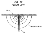
- a MI element Since a MI element has normally a property that it is sensitive in the longitudinal direction of the element, it is necessary to approach or engage with one end of the element with the recording medium to hence draw the magnetic flux to the interior of the element.
- the magnetic flux concentrates at the end tip of MI element 102, and rapidly decreases as deviated from the medium 100, thereby the region having an increased impedance change concentrates at the end tip of MI element 102, and hence the sufficient sensitivity of MI element 102 as a whole cannot be attained.
- the object of the present invention is to provide a magnetic head for reproducing digital magnetic recording information constructed by using a MI element, in which magnetic impednace effect is sufficently utilized to provide high sesitivity and excellent reproduction and to meet with high density of recording.
- the present invention is to provide a magnetic head, which is magnetized discontinuously in one direction or continuously in the alternative direction, the digital signal mentioned above is reproduced from a magnetic recording medium, wherein the boundary of the adjacent oppositely magnetized regions is formed as a straight line along a direction intersecting the aforementioned relative displacement direction: and the magnetic head comprises a MI element formed as a straight line as a whole, the above-mentioned MI element is located to oppose the surface of the medium in parallel therewith, and the longitudinal portions of the element is oriented to be shifted by a predetermined amount of angle with reference to the direction of magnetization of the magnetic medium; and as a result, the structure has been selected so as to enable to detect an external magnetic field from the recording medium to obtain a reproduced signal.
- FIG.1A to FIG.5 illustrate the first embodiment according to the present invention.
- FIGS.1A and 1B are fundamental illustrations of the first embodiment, wherein FIG.1A shows the positional relationship between a MI element and a magnetic recording medium (hereinafter, sometimes abbreviated as simply “medium”) in the direction in parallel to the surface of the medium and FIG.1B shows the same, but in the direction along a vertical section of the medium .
- medium a magnetic recording medium
- a magnetic recording medium 10 is formed, for example, as a magnetic tape, and moves along the longitudinal direction of medium 10 formed as a magnetic head relative to MI element 11 shown as the lateral direction in FIG.1A. Either the medium 10 or magnetic element may be moved relative to the other.
- the medium 10 is magnetized alternatively and continuously in the opposite direction, and, alternatively, magnetized discontinuously in one direction, with the predetermined shortest recording bit length b as a unit, as shown in FIG.2 thereafter, wherein the boundary line 11 is formed as a straight line perpendicular to the lengthy direction of medium 10.
- the direction of line 11 may be a somewhat angled direction relative to the aforementioned perpendicular direction.
- the shortest recording bit length herein is defined in the relative movement direction of medium 10, and is the shortest length of the recorded region as a unit in order to express each bit of the digital information (there are one or more kinds of length according to the modulation types for digital signals).
- the MI element 12 is composed of a combined figure of straight lines formed of amorphous wire or highly permeability magnetic layer so as to have magnetic anisotropy in the manner that the direction of the easy magnetizable axis is perpendicular with reference to the longitudinal direction of the MI element, so that the detection sensitivity for an external magnetic field H ex is exhibited in the longitudinal direction, based on the magnetic impedance effect.
- the MI element 12 is formed on the surface of a flat substrate made of a non-magnetic material such as glass, so as to be opposed in parallel relative to the surface (as its recording surface) of medium 10 with a predetermined spacing therebetween, and to be angled relative to the boundary line 11 of magnetization by a predetermined angle "theta" in a plane in parallel with the surface of the medium.
- the purposes for providing inclination or angle include, one for achieving an increased length S of MI element 12 larger than the magnetized width of the shortest recording bit length b, and the other for extending both ends of MI element 12 to engage with the boundary of magnetized edges of the shortest recording bit length b, in order to draw the flux from the medium 10 into substantially the entire MI element 12.
- terminals 13A and 13B Connected to the ends of MI element 12 are terminals 13A and 13B, which may be formed so as to extend from the MI element 12 with the same material, or formed as a separate conductive layer with a material different from that of MI element 12.
- a high frequency current is applied via terminals 13A and 13B to MI element 12, whereby, according to magnetic impedance effect, the impedance between terminal ends of MI element 12 varies in response to the external magnetic field of medium 10, so that the amplitude voltage between the terminal ends varies, and such varied voltage is derived and processed to obtain a reproduction signal.
- a MI element is coupled as an oscillating circuit element in, for example, a Collpitz oscillator, and the change of an external magnetic field is derived as an amplitude voltage change of an output of the oscillator, which output is subjected to detection or like process to obtain a reproduced signal.
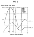
- FIGS.2 and 3 illustrate the test result for obtaining the data for setting the most preferable value of the inclination angle "theta" between the longitudinal direction of the element 12 and the boundary 11 of the medium 10.
- FIG.2 shows the arrangement for the test mentioned above.
- the MI element 12 was fabricated in the manner that a high permeability magnetic layer of Fe-Ta-C type is formed to a thickness of 2 microns on a flat rectangular glass substrate, and, since a pattern of a single line of 3mm in length would be of low impedance, is formed to have a pattern width of 16 microns so that four patterns were folded in parallel with each other in the shape of meandering, thereby configured in entirely straight lines combined together.
- the spacing d between the medium 10 and MI element 12 was 50 microns for one and 120 microns for the other.
- a bias magnetic field for obtaining sensitivity of MI element 12 was applied about 1 gauss, and a current of 20 MHz was allowed to flow via terminals 13A and 13B across the MI element 12, passed via a detector circuit, and thereafter the change of the terminal voltage was amplified by 750 times and measured. The result therefor is shown in FIG.3.
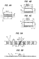
- FIG.4A, 4B and 4C as sectional views, wherein it is found, in the case that the spacing d between the medium 10 and MI element 12 is very close to zero, the most preferable angle is obtained when the length of the element 12, S x sin ⁇ , is equal to the shortest recording bit length b as shown in FIG.4A.
- the spacing d increases, the magnetic flux produced from magnetization of the medium 10 is eased to enter inwardly from both sides of MI element 12, so that the effective length S' of the element 12 becomes shorter than the value S.
- the angle ⁇ should be larger than its calculated value in order to coincide " S'sin ⁇ " with b as shown in FIG.4C.
- the medium 10 has a plurality of separate regions each being magnetized in the same direction, and the same result is obtained also in the case of FIG.1, in which each of the regions are magnetized alternatively in the opposite direction to each other along the relative movement direction.
- T St cos ⁇
- a single MI element is used to form a magnetic head.
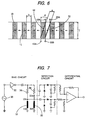
- FIG.6 is a schematic illustration of such an embodiment. As shown in FIG.6, two MI elements 12 and 22 are side by side arranged away from each other by a predetermined spacing g (the distance between the centers) along the relative movement direction of the medium 10.
- g the distance between the centers
- MI elements 12 and 22 are opposed in parallel with a spacing d on the surface of the medium 10 in the same manner as those in Embodiment 1, so that the longitudinal direction of the elements 12 and 22 are inclined by an angle ⁇ relative to the direction of boundary 11.
- the angle ⁇ is, the same as Embodiment 1:
- the same construction is selected for MI elements 12 and 22 for providing the performance as same as possible for the differential detection. It is also preferable to provide the spacing g which is equal to the shortest recording bit length b of the medium 10, wherein the g of either wider or narrower produces a peak shift or level lowering due to the interference caused between symbols.
- FIG.7 The circuit construction for obtaining a reproduced signal from the detection signal of MI elements is shown in FIG.7, in which a high frequency current produced from an external oscillation source 30 of a bias circuit is applied to MI elements 12 and 22 across the terminals 13A and 23A via a buffer 32 and resistors 34 and 36 for impedance adjustment. Terminals 13B and 23B of MI elements 12 and 22 are connected to the earth.
- the circuit is basically a bridge circuit, wherein a detection output of MI elements is derived across the terminals 13A and 23A, each is passed via one of two systems of detection circuits each including a capacitor, a diode and a resistor, fed to a differential amplifier and there differentially amplified, and a reproduced output is obtained.
- any same-phased noise such as an external noise is removed through differential amplification, thereby improving the S/N ratio.
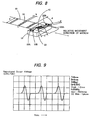
- FIG.9 shows an example of the reproduced output waveform by the circuit in FIG.7.
- the magnetizing direction is one direction along the longitudinal direction, that is the relative movement direction of the medium 10, and along which the magnetization was performed.
- the MI element 12 and 22 was fabricated in the manner that a high permeability magnetic layer of Fe-Ta-C type is formed to a thickness of 2 microns on a flat rectilinear glass substrate, and, since a pattern of a single line of 3mm in length would be of low impedance, is formed to have a pattern width of 16 microns so that four patterns were folded in parallel with each other in the shape of meandering, thereby configured in entirely straight lines combined together.
- the two elements were formed with a distance of 0.25mm therebetween, and, for obtain an adequate sensitivity, a bias magnetic field of in the extent of about one gauss was applied in the longitudinal direction of the elements.
- the measuring circuit is that shown in FIG.7, in which the oscillator frequency of an external oscillator 30 to apply a high frequency current for MI elements was 20 MHz, and the gain of the differential amplifier was 750 times.
- the reproduced output waveform is a waveform which has alternatively a positive and a negative peak at the boundary of the line width of the printed region 14 (magnetized region).
- the peak state each of both ends of one MI element intersects the both boundaries of the line width so that the impedance change is maximum, while each end of the other element does not intersect the line width so that no impedance change occurs, thereby the differential output becomes maximum.
- the output of 1 volt peak to peak is obtained, and the S/N ratio is also improved, thereby the sensitivity being excellent.
- the reproduction with the improved S/N ratio and high sensitivity is achieved.
- Embodiments 1 and 2 there is still the limitation in use with the high density recording medium. More preferably, the scheme of FIG.10 is further suitable for use with the high density recording medium.
- the substrate of a magnetic head is a pair of glass substrates 26A and 26B bonded together so as to form an entirely flat rectangle.
- the bonded surface is formed to direct the direction normal to the surface of the recording medium 10, on the one of the bonded surface a MI element 28 is formed as a high permeability magnetic layer, whose straight-lined edge is exposed on the surface of substrates 26A and 26B and arranged in parallel with the surface of the recording medium 10, whereby the bonded surface on which MI element is formed may be also as a surface slightly inclined from the direction normal to the surface of recording medium 10.
- a pair of terminals 29A and 29B are, respectively, coupled on opposite ends of MI element 28, each being formed as a conductive thin layer on the external surface adjacent the both sides of the bonded surface of substrate 26A or 26B, on which a MI element 28 is formed.
- the thickness of the high permeability magnetic layer of recording medium 10 of MI element 28 functions as a width for detecting a magnetic field, so that it is suitable for also reproduction from a high density recording medium.
- the read out is enabled even the shortest recording bit length b is lower than 1 micron.
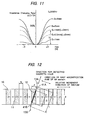
- FIG.11 shows the impedance changing characteristics of a MI element 12 in the construction of FIG.2, by changing the length S, formed of a high permeability magnetic layer of Fe-Ta-C type to a thickness of 2 microns and a width of 24 microns on a flat rectilinear glass substrate with meandering. As shown, as the length S approaches 1 mm, the characteristics rapidly decrease and finally almost no magnetic impedance effect is exhibited when reached to 1 mm.
- the disadvantage of decreasing the thickness is that the requirement for applying a high frequency current higher than 100 MHz as the drive current for the element is caused, for the reason of further reducing the thickness of skin effect to increase the magnetic impedance effect, which is likely to lead to instability of the sensor output due to the floating capacity. Also, reducing the thickness less than or equal to 1 micron causes instability of the magnetic wall structure, and also instability of the magnetic impedance characteristics.
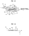
- FIGS.12 to 14 a structure as shown in FIGS.12 to 14 has been introduced.
- the entire length L of the magnetic layer forming MI element 12 shown in FIGS.1 and 2 is increased than the length S (hereinafter, referred to "operational length") utilized to perform magnetic detection by magnetic impedance effect, and, as shown in FIG.14, a conductive layer 42 is laminated on the upper surface of the extending region 41A (on 41B, also) of ends of the magnetic layer, by the material of copper, aluminum or gold.
- Such lamination of layer 42 may be also carried out on the lower surface of extending region 41A or 41B, or also may be on both the upper and lower surfaces, and the thickness thereof, although the relation with the specific resistivity of magnetic material of MI element 12 will be considered, may be preferably 0.5 to 2 microns.
- the purpose of such lamination of the conductive layer 42 onto the extending regions 41A and 41B is to suspend the magnetic impedance effect in such region.
- the magnetic impedance effect is exhibited.
- this magnetic impedance effect at the extending regions 41A and 41B can be suspended.
- the magnetic impedance effect is represented by the dotted line, when the length S of the operational region and the entire length L of the MI element are designated such that S is 0.5 and 1 mm, and L is fixed as 2 mm.
- the solid line represents the data when no lamination of the extending regions 41A and 41B is provided.
- FIG.15 represents the relation between the maximum impedance change V and the length S of the operational region relating to MI element shown in FIG.11.
- the length S is lower than 2 mm
- the influence by the demagnetizing field is considerably suspended.
- the extending regions 41A and 41B may not be extended along the extending line of the operational region of length S of the magnetic material of MI element 12, and the extending regions 41A and 41B may be of having a turned portion from the boundary relative to the operational region having a length S as shown in the variation of FIG.16.
- the present embodiments provide a magnetic head for reproducing a digital signal from a magnetic recording medium which is magnetized discontinuously in one direction or continuously in the alternative direction, the digital signal mentioned above is reproduced from a magnetic recording medium, wherein the boundary of the adjacent oppositely magnetized regions is formed as a straight line along a direction intersecting the aforementioned relative displacement direction: and the magnetic head comprises a MI element formed as a straight line as a whole, the above-mentioned MI element is located to oppose the surface of the medium in parallel therewith, and the longitudinal portions of the element is oriented to be shifted by a predetermined amount of angle with reference to the direction of magnetization of the magnetic medium, and an external magnetic field is detected using the MI element from the magnetic recording medium, thereby obtaining a reproduced signal, wherein it is possible to have the length of the MI element decreased than the shortest recording bit length of the recording medium to reduce the demagnetizing field of the element itself, and to receive the magnetic flux from the recording medium by the MI element as
- a pair of MI elements are side by side arranged away from each other by a predetermined spacing along the relative movement direction of the medium, so that the output of the MI elements are differentially amplified to produce a reproduction signal.
- any same-phased noise such as an external noise is removed through differential amplification, thereby improving the S/N ratio.
- the entire length L of the magnetic layer forming MI element is increased than the length S utilized to perform magnetic detection by magnetic impedance effect, and a conductive layer is laminated on the extending region of ends of the magnetic layer, thereby, even the track width of the recording medium is narrow so that the length S of the magnetic layer is small, the influence by the demagnetizing field is suspended, and a sufficient output characteristic is obtained.
- a magnetic head for reproducing digital magnetic recording information using a MI head which is a magnetic detection element utilizing magnetic impedance effect
- the magnetic recording medium 10 is magnetized alternatively, in the opposite direction along a relative movement direction relative to the magnetic head, the boundary 11 of magnetization is a straight line normal to the relative movement direction, and the MI element 12 opposes in parallel with the surface of the recording medium 10.
- the MI element is positioned so that its longitudinal direction is inclined by an angle ⁇ relative to the direction of the boundary 11 of magnetization.
- a high frequency current is applied via terminals 13A and 13B to obtain a reproduced signal through the magnetic impedance effect.
Landscapes
- Physics & Mathematics (AREA)
- General Physics & Mathematics (AREA)
- Engineering & Computer Science (AREA)
- Manufacturing & Machinery (AREA)
- Magnetic Heads (AREA)
- Recording Or Reproducing By Magnetic Means (AREA)
Applications Claiming Priority (4)
| Application Number | Priority Date | Filing Date | Title |
|---|---|---|---|
| JP11583696 | 1996-05-10 | ||
| JP115836/96 | 1996-05-10 | ||
| JP84748/97 | 1997-04-03 | ||
| JP08474897A JP3639407B2 (ja) | 1996-05-10 | 1997-04-03 | 磁気ヘッド |
Publications (2)
| Publication Number | Publication Date |
|---|---|
| EP0806762A2 true EP0806762A2 (de) | 1997-11-12 |
| EP0806762A3 EP0806762A3 (de) | 1998-07-08 |
Family
ID=26425732
Family Applications (1)
| Application Number | Title | Priority Date | Filing Date |
|---|---|---|---|
| EP97107680A Withdrawn EP0806762A3 (de) | 1996-05-10 | 1997-05-09 | Magnetkopf |
Country Status (3)
| Country | Link |
|---|---|
| US (1) | US5903414A (de) |
| EP (1) | EP0806762A3 (de) |
| JP (1) | JP3639407B2 (de) |
Families Citing this family (4)
| Publication number | Priority date | Publication date | Assignee | Title |
|---|---|---|---|---|
| JP3096413B2 (ja) * | 1995-11-02 | 2000-10-10 | キヤノン電子株式会社 | 磁気検出素子、磁気センサー、地磁気検出型方位センサー、及び姿勢制御用センサー |
| JP2002056510A (ja) * | 2000-08-07 | 2002-02-22 | Matsushita Electric Ind Co Ltd | シールド型磁気ヘッド並びに磁気再生装置 |
| US6798597B1 (en) * | 2001-02-02 | 2004-09-28 | Marvell International Ltd. | Write channel having preamplifier and non-uniform transmission line |
| JP4695325B2 (ja) * | 2001-09-17 | 2011-06-08 | キヤノン電子株式会社 | 磁気検出素子とその製造方法及び該素子を用いた携帯機器 |
Family Cites Families (9)
| Publication number | Priority date | Publication date | Assignee | Title |
|---|---|---|---|---|
| US4527202A (en) * | 1980-11-20 | 1985-07-02 | Victor Company Of Japan, Limited | Method and apparatus for recording/reproducing a control signal on and from video signal recordings by an erase head |
| JPS58185007A (ja) * | 1982-04-21 | 1983-10-28 | Toshiba Corp | 磁気再生装置 |
| JP2692719B2 (ja) * | 1992-01-09 | 1997-12-17 | 日本電信電話株式会社 | 磁気抵抗効果型磁気ヘッド |
| JPH06168420A (ja) * | 1992-11-30 | 1994-06-14 | Mitsumi Electric Co Ltd | 磁気ヘッド |
| JP3197414B2 (ja) * | 1993-12-22 | 2001-08-13 | 科学技術振興事業団 | 磁気インピーダンス効果素子 |
| JPH07320227A (ja) * | 1994-05-20 | 1995-12-08 | Sony Corp | 磁気的記録及び/又は再生方法、磁気ヘッドアセンブリ並びに磁気的記録及び/又は再生装置 |
| JPH0875835A (ja) * | 1994-09-09 | 1996-03-22 | Mitsumi Electric Co Ltd | 磁気インピーダンス素子および磁気検出回路 |
| JPH08273113A (ja) * | 1995-03-29 | 1996-10-18 | Canon Electron Inc | 磁気ヘッド及びその製造方法 |
| JPH09113590A (ja) * | 1995-10-18 | 1997-05-02 | Canon Electron Inc | 磁気センサー |
-
1997
- 1997-04-03 JP JP08474897A patent/JP3639407B2/ja not_active Expired - Fee Related
- 1997-05-08 US US08/854,061 patent/US5903414A/en not_active Expired - Lifetime
- 1997-05-09 EP EP97107680A patent/EP0806762A3/de not_active Withdrawn
Also Published As
| Publication number | Publication date |
|---|---|
| US5903414A (en) | 1999-05-11 |
| JPH1027317A (ja) | 1998-01-27 |
| JP3639407B2 (ja) | 2005-04-20 |
| EP0806762A3 (de) | 1998-07-08 |
Similar Documents
| Publication | Publication Date | Title |
|---|---|---|
| JPS63117309A (ja) | 磁気抵抗性読取変換器 | |
| US4881143A (en) | Compensated magneto-resistive read head | |
| US5357388A (en) | Shorted dual element magnetoresistive reproduce head exhibiting high density signal amplification | |
| US5218497A (en) | Magnetic recording-reproducing apparatus and magnetoresistive head having two or more magnetoresistive films for use therewith | |
| US4122505A (en) | Magneto-resistive reading head with suppression of thermal noise | |
| US5260652A (en) | Magnetoresistive sensor with electrical contacts having variable resistive regions for enhanced sensor sensitivity | |
| US3969769A (en) | Magneto-resistive head | |
| US5926019A (en) | System for evaluating the play back of magnetoresistive heads | |
| JPS6350768B2 (de) | ||
| US6073845A (en) | Recording medium on which information is recorded in intermittent pattern, and method of and apparatus for reproducing the information | |
| JPH01208715A (ja) | 磁気抵抗ヘッドセンサー | |
| JPH01277313A (ja) | データ読み取りの改良のための突起を有する磁気抵抗検出素子 | |
| US5903414A (en) | Magnetic head utilizing magnetic impedance effect | |
| EP0372420B1 (de) | Magnetisches Aufzeichnungs- und Abspielgerät sowie magnetoresistiver Kopf zum Einsatz darin | |
| Jeffers et al. | Unshielded magnetoresistive heads in very high-density recording | |
| JP3394549B2 (ja) | ホリゾンタル磁気抵抗効果型薄膜磁気ヘッド | |
| US4821012A (en) | Magnetoresistive element | |
| EP0613120A2 (de) | Magnetowiderstanddünnfilmmagnetkopf und Vormagnetisierungscharakteristikmessmethode | |
| JPH07109649B2 (ja) | 磁気抵抗効果ヘツド | |
| US6590740B2 (en) | Shielded magnetic head and magnetic reproducing apparatus | |
| JPS6394413A (ja) | 磁界感応トランスデューサー用シールド | |
| KR19990057744A (ko) | 소프트 어제이션트 레이어로 바이어스된 자기 저항 헤드 | |
| JPH0547885B2 (de) | ||
| JPS58166526A (ja) | 磁気抵抗効果型磁気ヘツド | |
| JPH01149286A (ja) | ブロッホラインメモリ及びその再生方法 |
Legal Events
| Date | Code | Title | Description |
|---|---|---|---|
| PUAI | Public reference made under article 153(3) epc to a published international application that has entered the european phase |
Free format text: ORIGINAL CODE: 0009012 |
|
| AK | Designated contracting states |
Kind code of ref document: A2 Designated state(s): DE FR GB IT |
|
| PUAL | Search report despatched |
Free format text: ORIGINAL CODE: 0009013 |
|
| AK | Designated contracting states |
Kind code of ref document: A3 Designated state(s): DE FR GB IT |
|
| 17P | Request for examination filed |
Effective date: 19981215 |
|
| 17Q | First examination report despatched |
Effective date: 19990510 |
|
| GRAP | Despatch of communication of intention to grant a patent |
Free format text: ORIGINAL CODE: EPIDOSNIGR1 |
|
| STAA | Information on the status of an ep patent application or granted ep patent |
Free format text: STATUS: THE APPLICATION IS DEEMED TO BE WITHDRAWN |
|
| 18D | Application deemed to be withdrawn |
Effective date: 20080311 |