EP0806710B2 - Stabilisation einer elektronischen Schaltung zur Regelung des mechanischen Gangwerks einer Zeitmessvorrichtung - Google Patents
Stabilisation einer elektronischen Schaltung zur Regelung des mechanischen Gangwerks einer Zeitmessvorrichtung Download PDFInfo
- Publication number
- EP0806710B2 EP0806710B2 EP97107371A EP97107371A EP0806710B2 EP 0806710 B2 EP0806710 B2 EP 0806710B2 EP 97107371 A EP97107371 A EP 97107371A EP 97107371 A EP97107371 A EP 97107371A EP 0806710 B2 EP0806710 B2 EP 0806710B2
- Authority
- EP
- European Patent Office
- Prior art keywords
- braking
- rotor
- pulses
- inhibition
- pulse
- Prior art date
- Legal status (The legal status is an assumption and is not a legal conclusion. Google has not performed a legal analysis and makes no representation as to the accuracy of the status listed.)
- Expired - Lifetime
Links
Images


Classifications
-
- G—PHYSICS
- G04—HOROLOGY
- G04C—ELECTROMECHANICAL CLOCKS OR WATCHES
- G04C10/00—Arrangements of electric power supplies in time-pieces
-
- G—PHYSICS
- G04—HOROLOGY
- G04C—ELECTROMECHANICAL CLOCKS OR WATCHES
- G04C3/00—Electromechanical clocks or watches independent of other time-pieces and in which the movement is maintained by electric means
Definitions
- the present invention relates to a timepiece comprising an electric energy generator comprising a rotor and means for supplying electrical energy in response to a rotation of the rotor, and being regulated by an electronic circuit comprising rotor braking means of the generator, according to the preamble of claim 1.
- a source of mechanical energy drives a generator of electrical energy to supply the electronic circuit.
- the rotor of the generator itself can be braked by the electronic circuit to regulate the mechanical movement by enslaving for example, the frequency of a quartz.
- the interest of these timepieces is to have a very precise movement, regulated by quartz or other, without requiring a battery or accumulator with limited life.
- Such a timepiece is described for example in US-A-3,937,001 in which the pulsation of the alternator voltage of the generator is compared to the frequency of a quartz.
- the rotor is braked by short-circuiting the generator by a resistor. But when the movement takes a certain advance, the braking time of the rotor of the generator can become very important, at the risk of seeing the supply voltage from the generator become insufficient for the electronic circuit.
- EP-A-0 679 968 discloses another timepiece overcoming this disadvantage, by providing for braking the rotor for short fixed time intervals relative to its rotation period.
- the document demonstrates in particular that the braking must be triggered at times when the value of the alternating voltage from the generator is low. Braking pulses are thus applied as soon as the alternating voltage changes sign, which is detected by a comparator whose threshold is set at the reference potential, the zero voltage.
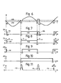
- FIGS. 1 to 4 illustrate the shape of the alternating voltage Ug and measurement pulses SM obtained with two threshold comparators of the state of the art. Measurement results carried out with a null voltage threshold comparator are illustrated in FIGS. 1 and 2.
- FIG. 1 represents the evolution of the voltage Ug as a function of time, the value 0 of the voltage corresponding to the zero threshold.
- FIG. 2 represents, as a function of time, the SM pulses at the output of the null threshold comparator, the measurement signal SM varying from a "0" state to a "1" state according to the result of the comparison. It is seen in particular that an electrical parasite on the voltage Ug at time t1 causes the appearance of a parasitic I1 pulse on the measurement signal SM. This electrical parasite can be simply a report of the mass noise.
- the threshold of the comparator must fulfill two contradictory conditions. On the one hand, it must be high enough to mask the spurious impulses. On the other hand, it must be low enough that the braking pulses occur when the generator voltage is low, as we saw earlier.
- Figures 3 and 4 are shown similarly to Figures 1 and 2 of the measurement results obtained with a high threshold comparator. Equivalently, the comparator could be a two-threshold Schmidt amplifier with different values.
- the threshold Ut is represented in dashed lines on the timing diagram of the voltage Ug of the generator, see FIG. 3. This shows a weakening of the voltage of the generator Ug during braking at time t4, and the appearance of double pulses 14 and 15 (see Figure 4), which is the opposite of the goal.
- An object of the present invention is to stabilize the operation of a timepiece with mechanical movement regulated by an electronic circuit.
- an object of the invention is to know the origin of such malfunctions and to remedy them.
- Another goal is to make a miniature timepiece whose electronic circuit is simple and reliable.
- the thresholds of the detection circuits used previously depend in fact on the value of the supply voltage. Surprisingly, during braking of the rotor, the weakening of the voltage of the generator is sufficient to derive the threshold of the comparator which then generates a new pulse. Thus, for a current comparator such as a Schmidt amplifier having a low threshold Uth positive and a low threshold Utb negative, the comparator delivers double pulses instead of delivering only one. In Indeed, the drop of the voltage Ug supplied by the generator can reach a value greater than the positive threshold Uth of the comparator, thus triggering the appearance of a parasitic pulse. This phenomenon occurs only during the braking command, so just after the appearance of the first pulse.
- a timepiece comprising an electric power generator comprising a rotor and means for supplying said electrical energy in response to a rotation of said rotor, a source of mechanical energy mechanically coupled to said rotor for driving it in rotation, measuring means coupled to said generator for generating pulses for measuring the pulsation of an alternating voltage supplied by the generator which corresponds to the pulsation of the rotor, braking means responsive to a braking command for applying a braking torque to said rotor, and an electronic circuit having reference means for producing a signal having a reference frequency, and servo means arranged to control said means of braking; braking when said measurement pulses are ahead of said reference signal of so that the reference frequency regulates the pulsation of said rotor and said mechanical source, this part being characterized in that said electronic circuit further comprises synchronous inhibition means (Inh) measuring pulses and arranged so that a duplication said measurement pulses is deleted.
- Inh synchronous inhibition means
- the detection of the measurement pulses is inhibited, so as to eliminate such pulse duplications without substantially delaying the braking with respect to the change of sign of the voltage of the generator.
- the invention provides that the inhibiting means are correlated with a braking command provided by the control loop.
- a preferred embodiment is characterized in that the inhibiting means generate a braking command, the delay of this command being controlled by the control loop.
- the inhibiting means comprise a time base and respond to the appearance or disappearance of a measurement pulse.
- the electromechanical part of the timepiece according to the invention is shown schematically in FIG. 5. It comprises a source 2 of mechanical energy such as a spiral spring, coupled via gear trains 4 symbolized by lines mixed with time display means, such as dial hands, the source 2 of mechanical energy being also coupled to a rotor 3a of an electric power generator 3.
- the generator 3 further comprises a coil 3b inductive, the rotor 3a having a bipolar magnet conventionally represented by an arrow. This part will not be described in detail because it can be done in various ways, well known to those skilled in the art.
- the source 2 of mechanical energy drives the rotation of the rotor 3a and an alternating voltage Ug appears at the terminals B0, B1 of the coil 3b.
- the terminal B0 is considered as the reference terminal having a reference potential V 0 .
- This alternating voltage Ug is applied to a rectifier 5 for supplying DC voltage to an electronic circuit 1 for regulating the movement.
- a preferred embodiment of a rectifier will be indicated later.
- the electronic circuit 1 can regulate the mechanical movement of the timepiece by acting on braking means of the rotor 3a of the generator 3 provided for this purpose.
- the watch movement will indicate the current time when the rotor is rotating at a given speed, which we will call normal speed.
- the timepiece further comprises means for measuring the speed of movement. They are preferably constituted by means for measuring the pulsation of the rotor.
- the invention seeks to obtain measurement pulses which correspond to each pulse of the rotor, for example one pulse per revolution. These measurement pulses are indeed processed by the electronic circuit 1 in order to measure the drift of the movement and possibly to provide a braking command. These measuring means and the pulse processing will be detailed with the electronic circuit.
- the braking is obtained by short-circuiting the coil 3b of the generator 3.
- the electric current then flowing in this shunt indeed causes the appearance of a magnetic field opposing the cause of the current and thus opposing the movement of the rotor . It is possible to derive the current in a low value resistor.
- the preferred embodiment of the invention provides an electronic switch K connected directly between the two terminals B0, B1 of the coil 3b of the generator. This gives a very powerful braking.
- the electronic switch K is advantageously constituted by a bipolar or field-effect transistor, as explained in the aforementioned EP-A-0 679 968. Other equivalents are well known to those skilled in the art. The operation of this electronic switch K will not be detailed here.
- FIG. 3 already described above, shows for example the shape of the alternating voltage Ug during a braking cycle, to be compared with FIG. 1 representing the voltage Ug in the absence of braking. It can be seen that over a half-period t0-t6, there is a time interval t4-t5, during which the braking is controlled, the short-circuit generator supplies all of its energy to the switch K.
- the document EP-A-0 679 968 indicates that the brake control must be applied at times when the voltage Ug is close to 0 and for a short period of time, preferably less than 1/8 of the pulsation of the alternating voltage Ug.
- the rotor 3a thus has a normal speed of four revolutions per second and the duration of the braking pulses applied to the switch K is limited to about 5 ms, ie 1/50 of the pulsation of 250 ms of Ug voltage.
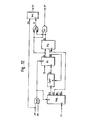
- the electronic circuit 1 for regulating the movement of the timepiece consists mainly of an oscillator Osc providing a signal having a base frequency FO, measurement means, referenced Trig and Inh, the pulsation of the rotor 3a and a frequency servo circuit, controlling a brake control of the rotor.
- the frequency control circuit controls the braking when measurement pulses IN supplied by the measuring means Trig, Inh, and having a frequency corresponding to the pulsation of the rotor, are in advance with respect to pulses, referenced FR, provided by the oscillator Osc, and having a reference frequency derived from the basic frequency FO of the oscillator Osc, for example by dividing the signal FO in order to obtain a signal having the reference frequency.
- the servocontrol circuit preferably comprises a frequency corrector Div which formats the signal having a base frequency FO and delivers pulses at a reference frequency FR.
- the corrector Div can be simply a frequency divider circuit, well known to specialists and therefore will not be detailed here.
- intermediate frequency pulses F1 can be extracted from such circuits.
- the oscillator Osc is a quartz having a natural frequency FO of 32,768 Hz.
- the divider Div divides the signal having the frequency FO in order to obtain a series of pulses FR having a reference frequency of 4 Hz corresponding to the normal pulsation of the rotor.
- F1 pulses with an intermediate frequency of 4'096 Hz can also be extracted from the divider.
- these values are given only as an example.
- pulses F1 which here have a period of 0.244 ms, are intended to serve as timebase or delay to the aforementioned braking control and to clock all the logic.
- the servocontrol circuit further comprises a comparator, referenced Cmp, delivering an AV signal indicating the advance (or delay) of the movement relative to the reference frequency FR.
- This comparator Cmp may for example be a down-counter, or reversible counter, totaling the difference of the number of measurement pulses IN, received on its input + ", and the number of reference pulses FR received on its input" - '', as described in EP-A-0679 968 mentioned above.
- the state or the level of the AV signal available at the output of the comparator Cmp then indicates whether the pulsations of the rotor are in advance or not on the reference frequency FR.
- the servocontrol circuit finally comprises a timer Tmr, or register, delivering pulses of fixed duration.
- a first of the two inputs of the timer Tmr is connected to the output of the circuit Inh, and the other input receives from the divider Div the pulses Fi used to determine the duration of the output pulses.
- the timer further comprises an enable terminal receiving the AV signal of the comparator Cmp.
- the timer Tmr delivers at its output braking pulses, referenced IF, of fixed duration after the appearance of measuring pulse IN, if however the signal AV indicates that the pulsations of the rotor are ahead of the reference frequency FR.
- the braking will indeed have a duration of less than 5 ms, by programming an internal timer counter Tmr counting twenty F1 pulses having a period of 0.244 ms to generate a braking pulse IF thus having a duration of 4 , 88 ms.
- Tmr Preferred timer embodiments Tmr will be detailed following the description of the means for measuring the pulsation of the rotor.
- FIG. 6 represents an exemplary timing diagram of the alternating voltage Ug delivered by the generator 3 when braking pulses are applied.
- dashed lines show two levels of threshold voltage Uth and Utb of reduced value with respect to the amplitude of the voltage Ug.
- the threshold Uth is positive, slightly higher than the reference value 0 of the alternating voltage Ug.
- the threshold Utb is negative, preferably symmetrical at the threshold Uth with respect to the voltage 0.
- the invention in fact provides that the means for measuring the pulsation comprise a Schmidt hysteresis or trigger amplifier, referenced Trig in FIG. 5.
- FIG. 7 shows a timing diagram of pulses obtained at the output of FIG. the Trig amplifier. It can be seen that the IM output of the amplifier goes to a first level (state 0) from the instant b2 at which the input voltage Ug becomes lower than the lower threshold Utb; the output IM remains at this first level as long as the voltage Ug is not greater than the upper threshold Uth.
- Schmidt trigger with positive threshold Uth and negative threshold Utb should not be sensitive to the return of voltage Ug to the value 0 during the braking periods.
- the electronic circuit 1 preferably has a continuous symmetrical supply V-, V0, V +.
- a good balanced power supply comprises a midpoint generator and a simple rectifier with a capacitor between two outputs V + and V-, the reference output V0 being taken at the midpoint.
- This solution has the disadvantage of reducing by half the amplitude of the measurable voltage Ug ug, already weak amplitude at the terminals of a miniature coil 3b.
- the preferred embodiment of the invention comprises a symmetrical rectifier 5 as illustrated in FIG. 5.
- This rectifier comprises in particular a reference output Vo connected to the reference terminal B0 of the generator 3, and two capacitors respectively arranged between a voltage output V + or V-, and the output V0.
- the operation of the rectifier circuit 5 for regulating the DC supply of the electronic circuit 1 will not be described in detail since it can be realized in various ways well known to those skilled in the art.
- each capacitor is recharged at each alternation substantially at the peak value of the alternating voltage Ug.
- FIGS. 6 to 11 A braking cycle is for example represented in FIG. state "1" of the AV signal. The phenomenon seems due to the drifting of the Uth and Utb thresholds of Schmidt Trig's "trigger". Note that there is no duplication of impulse at the beginning of the braking cycle.
- FIG. 7 shows, for example, the absence of duplication at the beginning of the pulse H3 at the moment of the first braking pulse F3, shown schematically in FIG. 11.
- the splitting of the pulse H3-H5 appears only at the second braking pulse F4. In fact, the peak value of the alternating voltage Ug is decreased after the first braking pulse F3.
- the value of the rectified voltage V + is weakened. This drift of the supply voltage seems to cause a drift of the thresholds Uth and Utb of the trigger Trig.
- the voltage drop Ug can reach a value greater than the threshold Uth thus triggering the appearance of a spurious pulse H5 shown in FIG. be also caused by the existence of a certain voltage of waste across the switch K (see Figure 5). This waste voltage could prevent the voltage Ug from returning to a strictly zero value.
- the invention provides means for synchronous inhibition of measurement pulses.
- the electronic circuit 1 furthermore comprises a synchronous inhibition circuit Inh receiving the measurement pulses IM delivered by the threshold comparator Trig, the assembly thus constituting the means for measuring the pulsation of the rotor. 3a.
- synchronous inhibition will be understood as an inhibition triggered by signals, preferably by internal pulses to the system formed by the timepiece, its generator, the electronic circuit and its oscillator.
- the inhibition of measurement pulses can be synchronized to the pulses themselves, a first pulse triggering the inhibition of the appearance of subsequent pulses.
- the present application is all "synchronous inhibition" without specifying the source of synchronization.
- the inhibition circuit Inh comprises a time base (internal or external) and normally transmits the measurement pulses IM coming from the amplifier Trig directly to the timer Tmr. However, when the inhibition circuit Inh is activated, the circuit no longer transmits the pulses IM. during an inhibition period. Inhibition starts with the appearance and / or the disappearance of a pulse, that is to say that the inhibition circuit reacts on the rising and falling edges of the pulses IM, and its duration. activation is timed by its time base. For example, referring to FIG. 6 and FIGS. 7 and 8, which respectively represent the different pulses transmitted by the amplifier Trig (FIG. 7) and by the inhibition circuit Inh (FIG. 8), the circuit of FIG.
- inhibition normally transmits the measurement pulses H1, H3 and H7, respectively in the form of pulses M1, M3 and M5, since their transitions at times b2, h3, b4, h7 are separated by time intervals greater than the inhibition time ti. But this inhibition circuit does not transmit the parasitic pulse H5 that appears during the inhibition time ti starting at the falling edge (time b4) of the pulse H3, see FIG. 8.
- the inhibition circuit generates a normal pulse IN of determined duration at each measurement pulse edge IM unless this edge appears during a normal pulse IN.
- Such an inhibition circuit can be implemented in a similar manner to the aforementioned timer Tmr.
- the circuit Inh comprises for example a monostable multivibrator sensitive to transitions of measurement pulses IM applied to its input. At the rising edge of a pulse IM, the monostable thus outputs a normal pulse IN of fixed duration. Similarly, at the falling edge of an IM pulse, the monostable delivers another normal pulse IN of fixed duration.
- the inhibition circuit receives on an input of pulses IF, represented in FIG. 11, each being a braking command for braking the rotor of the generator, resulting from the timer Tmr and the inhibition corresponds to the braking time tf, see FIG. 11. Indeed, as has been observed, the spurious splitting pulses only appear during braking. Synchronous inhibition is thus achieved with the advantage of simplicity.
- the preferred embodiment of the invention has an inhibition command II of longer duration than the IF braking command, and covering all braking instants.
- the inhibition pulse It thus covers the instants following the end of the braking pulse IF and the appearance of the pulse It may precede the appearance of this pulse IF This "overflow" ensures that propagation delays of inhibition or braking or voltage Ug still trigger parasitic pulses.
- the timer Tmr has two outputs which deliver a muting pulse II and a braking pulse IF correlated.
- correlation refers to the simultaneous occurrence, or with a substantially constant time delay, of two physical phenomena such as signals or pulses. Note, however, that these two phenomena may have different durations. For example, temporarily correlated pulses may have different widths, which is well known to those skilled in the art.
- the timer Tmr receives the pulses F1 of period 0.244 ms on a first input connected to the output of the divider Div.
- a normal pulse IN appears on the other input, which is connected to the output of the inhibiting means, and if the state of the advance signal AV controls it by means of a pulse on the input of validation of the timer (see Figure 5), the timer Tmr immediately delivers an inhibition pulse II.
- a braking pulse IF also appears at the output of the timer Tmr with a delay of a period F1 of 0.244 ms on the beginning of the inhibition pulse II and an internal counter limits its duration to 21 pulses F1 is 5.124 ms. Indeed, the internal meter must ensure that the braking time is around 5 ms. Another internal counter limits the duration of pulse II to 25 pulses F1, 6.1 ms. The inhibition pulse II therefore ends 0.732 ms after the end of the braking pulse IF.
- Tmr timer electronic circuit providing such pulses Inhibition II and braking pulses IF will now be described in detail with reference to FIG. 12.
- the circuit shown is a logic circuit receiving the intermediate frequency pulse signals F1, the advance signal AV (or delay) and the aforementioned measuring pulses IM and delivering IF braking pulse signals, inhibition pulses II and normal IN pulses mentioned above.
- the logic circuit of FIG. 12 comprises a shift register Reg, receiving the pulses F1 at the clock input, the register having four outputs R0, R1, R2 and R3, on which a pulse appears successively.
- the pulses F1 have a period of 0.244 ms.
- the output R3 thus generates pulses having a period of 0.976 ms, similar but delayed by 0.244 ms with respect to the pulses of the output R2.
- the register Reg has an activation terminal S which is connected to the output of an AND gate, referenced And, carrying out the AND logical operation between the advance signal AV and the pulse signal. measure IM.
- terminal S goes to state "1”
- Reg register is activated and output R1 goes to state "1”.
- the output R2 goes to state "1", the output R1 being reset to the state "0".
- the output R3 is connected to a counter Cptr which will make it possible to limit the duration of the pulses IF, II and IN.
- the counter may, for example, increment to a value of five, a retaining output Q going to state "1" after a count of five pulses R3.
- the count is initialized and the output Q is reset to the "0" state if the initialization terminal R is in the "1" state.
- the output Q of the counter Cptr is connected to the clock input of a flip-flop Fli, of flip-flop type D. This flip-flop further comprises a data input receiving the state "0".
- a setting terminal S makes it possible to force the state of the outputs Q and NQ respectively to states "1" and "0".
- the set terminal S is also connected to the output of the logic gate And.
- the advance signal AV is in the state "1".
- a measurement pulse IM goes to state "1".
- the terminals S of the register Reg and the flip-flop Fli are then in the state "1".
- the flip-flop is activated and its output Q goes to state "1".
- the output signal Q of the flip-flop Fli is applied to an input of an "Or” gate, referenced Or, the output of which delivers the inhibition pulses II. From moment h, the inhibition pulse signal II thus goes to state "1".
- the gate OR actually performs the OR logic operation between the Q output of flip-flop and a Q output of another Flo flip-flop.
- This second Flo flip-flop D receives on its data input the output signal Q flip flop.
- the output signal R2 of the shift register Reg is applied to the clock input of the Flo flip-flop.
- the transfer of the data Q on the output of the flip-flop will thus be delayed until the next transition of the signal R2.
- the two Q outputs Fli and Flo flip-flops are also applied to the two inputs of a gate And carrying out the AND logical operation.
- the transition of the signal R2 occurs 0.244 ms after the instant h. So that the braking pulse IF appears 0,244 ms after the appearance of the inhibition pulse Il.
- the output NQ of the flip-flop Fli is connected to the initialization terminal R of the counter Cptr.
- the counter is activated and starts counting the pulses R3 from the register Reg.
- the Q output of the counter Cptr will change to state "1".
- This transition on the clock input causes flip flop F i to reproduce at the output Q the state 0 ° of the data.
- the output NQ then goes to state "1” by initializing the counter Cptr and its output Q.
- the outputs Q of the counter Cptr and the flip-flop then remain in the state "0", this situation lasting as long as a transition from state "0" to "1" does not appear on the terminal S of setting of a flip-flop Fli.
- the counting of the counter Cptr is synchronized on the signal R3 O, 488 ms after the instant h.
- the count lasts 4.88 ms as previously indicated.
- the Q output of the counter Cptr goes to the state "1
- the counter is reset and the remains until a new measuring pulse IM, the braking pulse signal IF thus returns to the state "0" at time h + 5,368 ms.
- this transition occurs 0.732 ms after the reset of the counter Cptr, ie at the instant h + 6.1 ms.
- the inhibition pulse It thus disappears 0.732 ms after the disappearance of the braking pulse IF.
- the signals of the timer circuit Tmr remain in this state as long as a new measurement pulse IM does not appear.
- the timer circuit Tmr delivers muting pulses II and braking IF, the duration of an inhibition pulse II covering and exceeding the duration of the braking pulse IF to avoid any error during commutations.
- the circuit of FIG. 12 also illustrates an embodiment of inhibition circuit Inh.
- the inhibition circuit Inh is a type D flip-flop sensitive to the state of the validation input E.
- the inhibition pulse signal It is applied to this input E, the data input receiving the measurement pulses IM and the data output delivering the normal pulses IN.
- the output of the normal IN pulses of such an Inh circuit copies the state of the measurement pulse signal IM only if the enable input E is in the "0" state.
- the inhibition ie when the inhibition signal II is in the "1" state (between the instant h and the instant h + 6.1 ms, according to the exemplary embodiment)
- the state of the output is unchanged regardless of the transitions of the measurement pulse signal IM.
- the inhibition means make it possible to eliminate the spurious pulses which caused an uncorrected delay of the timepiece.
- inhibiting means combined with measuring means comprising a hysteresis amplifier give the timepiece good immunity to electrical noise in general.
- the capacitors of the rectifier 5 may advantageously have relatively low capacitances since it is no longer necessary to provide threshold voltages that are strictly stable to the measurement means.
- the durations of the braking pulses IF can be modulated according to the importance of the advance of the measurement pulses IM on the reference pulses FR.
- This variant is particularly applicable to a control circuit having a phase-locked loop, the circuit then providing an AV signal whose level can vary proportionally to the phase shift of the pulses IN relative to the braking pulses IF, and the level of the AV signal then modulating the duration of the braking pulses IF supplied by the timer Tmr.
Landscapes
- Physics & Mathematics (AREA)
- General Physics & Mathematics (AREA)
- Engineering & Computer Science (AREA)
- Power Engineering (AREA)
- Electromechanical Clocks (AREA)
- Control Of Eletrric Generators (AREA)
Claims (6)
- Zeitmessvorrichtung, umfassend:- einen Generator (3) für elektrische Energie, der einen Rotor (3a) und Mittel (3b) zum Liefern der elektrischen Energie ais Antwort auf eine Drehung des Rotors (3a) enthält,- eine Quelle (2) für mechanische Energie, die mit dem Rotor (3a) mechanisch gekoppelt ist, um ihn rotatorisch anzutreiben,- Messmittel (Trig), die mit dem Generator (3) gekoppelt sind, um Messimpulse für die Frequenz einer vom Generator (3) gelieferten Wechselspannung, die der Frequenz des Rotors (3a) entspricht, zu erzeugen,- Bremsmittel (K), die auf einen Bremsbefehl ansprechen, um an den Rotor (3a) ein Bremsmoment während begrenzter Zeitperioden anzulegen, und- eine elektronische Schaltung (1), die Referenzmittel (Osc) zum Erzeugen eines Signais mit einer Referenzfrequenz (FR) sowie Regelungsmittel (Div, Cmp, Tmr), die so beschaffen sind, dass sie die Bremsmittel (K) steuern, wenn die Messimpulse in bezug auf das Referenzsignal voreilen, umfasst, so dass die Referenzfrequenz die Frequenz des Rotors und die mechanische Quelle reguliert,wobei die Vorrichtung dadurch gekennzeichnet ist, dass die elektronische Schaltung (1) ausserdem Mittel (Inh) zum synchrones Sperren der Messimpulse (IM) enthält, die so beschaffen sind, dass eine Verdoppelung der Messimpulse während der begrenzten Bremszeitperioden unterdrückt wird.
- Zeitmessvorrichtung nach Anspruch 1, dadurch gekennzeichnet, dass die Sperrmittel (Inh) mit den Bremsmitteln (K) in einer Wechselbeziehung stehen.
- Zeitmssvorrichtung nach Anspruch 1oder 2, dadurch gekennzeichnet, dass ein Bremsbefehl (IF), der von der Regelungsschleife geliefert wird, auch zum Steuern der Sperrmittel (Inh) verwendet wird, wobei die Schleife eine Verzögerung dieses Befehls steuert.
- Zeitmessvorrichtung nach einem der Ansprüche 1 bis 3, dadurch gekennzeichnet, dass die Sperrmittel (Inh) die Übertragung der Messimpulse (IM) während einer verzögerten Dauer sperren, wobei die Sperrung bei Auftreten oder Verschwinden eines Messimpulses ausgelöst wird.
- Zeitmessvorrichtung nach einem der Ansprüche 1 bis 4, dadurch gekennzeichnet, dall die Messmittel (Trig) ein Hysterese-Filter wie etwa einen Schmidt-Verstärker umfassen.
- Zeitmessvorrichtung nach einem der Ansprüche 1 bis 5, dadurch gekennzeichnet, dass der Stromgenerator mit einem Gleichrichter verbunden ist, der eine symmetrische Versorgung schafft.
Applications Claiming Priority (2)
| Application Number | Priority Date | Filing Date | Title |
|---|---|---|---|
| FR9605720A FR2748583B1 (fr) | 1996-05-07 | 1996-05-07 | Stabilisation d'un circuit electronique de regulation du mouvement mecanique d'une piece d'horlogerie |
| FR9605720 | 1996-05-07 |
Publications (3)
| Publication Number | Publication Date |
|---|---|
| EP0806710A1 EP0806710A1 (de) | 1997-11-12 |
| EP0806710B1 EP0806710B1 (de) | 2000-08-16 |
| EP0806710B2 true EP0806710B2 (de) | 2008-01-23 |
Family
ID=9491926
Family Applications (1)
| Application Number | Title | Priority Date | Filing Date |
|---|---|---|---|
| EP97107371A Expired - Lifetime EP0806710B2 (de) | 1996-05-07 | 1997-05-05 | Stabilisation einer elektronischen Schaltung zur Regelung des mechanischen Gangwerks einer Zeitmessvorrichtung |
Country Status (8)
| Country | Link |
|---|---|
| US (1) | US5740131A (de) |
| EP (1) | EP0806710B2 (de) |
| JP (1) | JP4065345B2 (de) |
| CN (1) | CN1114137C (de) |
| DE (1) | DE69702811T3 (de) |
| FR (1) | FR2748583B1 (de) |
| SG (1) | SG63704A1 (de) |
| TW (1) | TW330252B (de) |
Families Citing this family (26)
| Publication number | Priority date | Publication date | Assignee | Title |
|---|---|---|---|---|
| EP0848842B2 (de) * | 1995-09-07 | 2006-04-19 | International S.A. Richemont | Uhrwerk |
| US6169709B1 (en) | 1995-09-07 | 2001-01-02 | Konrad Schafroth | Watch movement |
| CH690523A5 (fr) * | 1996-12-09 | 2000-09-29 | Asulab Sa | Pièce d'horlogerie comportant une génératrice d'énergie électrique. |
| DE69809363T2 (de) * | 1997-09-26 | 2003-09-04 | Seiko Epson Corp., Tokio/Tokyo | Elektrisch geregelte mechanische Uhr |
| EP0942340B1 (de) | 1997-09-30 | 2006-09-20 | Seiko Epson Corporation | Drehkontrollvorrichtung und drehkontrollverfahren |
| JP3472877B2 (ja) * | 1997-09-30 | 2003-12-02 | セイコーエプソン株式会社 | 電子制御式機械時計およびその制御方法 |
| US6314059B1 (en) * | 1997-09-30 | 2001-11-06 | Seiko Epson Corporation | Electronically controlled, mechanical timepiece and control method for the same |
| US6795378B2 (en) | 1997-09-30 | 2004-09-21 | Seiko Epson Corporation | Electronic device, electronically controlled mechanical timepiece, and control method therefor |
| JP3006593B2 (ja) * | 1997-09-30 | 2000-02-07 | セイコーエプソン株式会社 | 電子制御式機械時計およびその制御方法 |
| US6584043B1 (en) * | 1998-11-17 | 2003-06-24 | Seiko Epson Corporation | Electronically controlled mechanical watch and method of preventing overcharge |
| WO2000031595A1 (fr) * | 1998-11-19 | 2000-06-02 | Seiko Epson Corporation | Compteur de temps mecanique commande electriquement et procede de blocage |
| CN100399217C (zh) * | 1999-03-03 | 2008-07-02 | 精工爱普生株式会社 | 电子设备及其控制方法 |
| JP3823741B2 (ja) * | 2001-03-06 | 2006-09-20 | セイコーエプソン株式会社 | 電子機器、電子制御式機械時計、それらの制御方法、電子機器の制御プログラムおよび記録媒体 |
| US6826124B2 (en) * | 2002-12-04 | 2004-11-30 | Asulab S.A. | Timepiece with power reserve indication |
| EP1521142B1 (de) * | 2003-10-01 | 2007-05-30 | Asulab S.A. | Uhr mit einem mechanischen Uhrwerk, das mit einem elektronischen Regulator gekoppelt ist |
| ATE363675T1 (de) * | 2003-10-01 | 2007-06-15 | Asulab Sa | Uhr mit einem mechanischen uhrwerk, das mit einem elektronischen regulator gekoppelt ist |
| EP1843227A1 (de) | 2006-04-07 | 2007-10-10 | The Swatch Group Research and Development Ltd. | Gekoppelter Resonator für Regelsystem |
| CH697273B1 (fr) * | 2006-07-26 | 2008-07-31 | Detra Sa | Dispositif d'échappement électromécanique et pièce d'horlogerie munie d'un tel dispositif |
| WO2014087481A1 (ja) * | 2012-12-04 | 2014-06-12 | 三菱電機株式会社 | 信号伝達回路 |
| EP2908187B1 (de) * | 2014-02-17 | 2016-10-19 | The Swatch Group Research and Development Ltd. | Regulierung eines Resonators einer Uhr durch Einwirkung auf die aktive Länge einer Spiralfeder |
| EP2908188B1 (de) * | 2014-02-17 | 2018-06-27 | The Swatch Group Research and Development Ltd. | Regulierung eines resonators einer uhr durch einwirkung auf die steifheit eines elastischen rückstellmittels |
| EP3432088A1 (de) * | 2017-07-17 | 2019-01-23 | The Swatch Group Research and Development Ltd | Elektromechanische uhr |
| EP3748438B1 (de) * | 2019-06-06 | 2022-01-12 | The Swatch Group Research and Development Ltd | Messung der präzision einer uhr, die einen kontinuierlich drehenden elektromechanischen transducer in ihrer analogen uhrzeitanzeigevorrichtung umfasst |
| EP4009119B1 (de) | 2020-12-07 | 2023-07-05 | The Swatch Group Research and Development Ltd | Uhrwerk, das einen generator und eine schaltung zur regulierung der drehfrequenz dieses generators umfasst |
| WO2022122670A1 (en) | 2020-12-10 | 2022-06-16 | Höganäs Ab (Publ) | New powder, method for additive manufacturing of components made from the new powder and article made therefrom |
| WO2022178785A1 (zh) * | 2021-02-25 | 2022-09-01 | 华为技术有限公司 | 整流器及其驱动方法、设备 |
Family Cites Families (17)
| Publication number | Priority date | Publication date | Assignee | Title |
|---|---|---|---|---|
| US664612A (en) | 1900-01-13 | 1900-12-25 | Daniel W Aylworth | Gate. |
| US3727079A (en) * | 1971-12-06 | 1973-04-10 | Ampex | Zero crossing detecting circuit |
| CH597636B5 (de) * | 1972-11-21 | 1978-04-14 | Ebauches Sa | |
| US4008866A (en) * | 1973-03-16 | 1977-02-22 | Vehicle Research Corporation | Compression energy transformation system for a supersonic wing |
| US3944936A (en) * | 1974-08-07 | 1976-03-16 | Rca Corporation | Zero crossover detector |
| JPS605915B2 (ja) * | 1975-04-07 | 1985-02-14 | セイコー光機株式会社 | 電気時計の駆動装置 |
| JPS53132386A (en) * | 1977-04-23 | 1978-11-18 | Seiko Instr & Electronics Ltd | Electronic watch |
| DE3767691D1 (de) * | 1986-12-03 | 1991-02-28 | Ebauchesfabrik Eta Ag | Schaltung zur formung des von einem kontakt produzierten signals. |
| US4799003A (en) * | 1987-05-28 | 1989-01-17 | Tu Xuan M | Mechanical-to-electrical energy converter |
| US4795915A (en) * | 1987-12-14 | 1989-01-03 | Motorola, Inc. | Zero crossing noise-rejecting digital filter |
| DE3903706A1 (de) * | 1988-02-09 | 1989-08-17 | Fraunhofer Ges Forschung | Uhr mit einem elektronischen uhrenbaustein |
| CH671669B5 (de) * | 1988-03-21 | 1990-03-30 | Phare Jean D Eve Sa Le | |
| US5043653A (en) * | 1990-01-17 | 1991-08-27 | Sundstrand Corporation | Noise filter for zero crossing detector |
| US5019722A (en) * | 1990-03-05 | 1991-05-28 | Motorola, Inc. | Threshold crossing detection with improved noise rejection |
| US5278462A (en) * | 1992-04-24 | 1994-01-11 | Fasco Controls Corporation | Threshold crossover detector with improved digital noise rejection |
| US5563532A (en) * | 1994-01-24 | 1996-10-08 | Advanced Micro Devices, Inc. | Double filtering glitch eater for elimination of noise from signals on a SCSI bus |
| CH686332B5 (fr) * | 1994-04-25 | 1996-09-13 | Asulab Sa | Pièce d'horlogerie mué par une source d'énergie mécanique et régulée par un circuit électronique. |
-
1996
- 1996-05-07 FR FR9605720A patent/FR2748583B1/fr not_active Expired - Fee Related
-
1997
- 1997-04-24 TW TW086105355A patent/TW330252B/zh active
- 1997-04-25 US US08/845,406 patent/US5740131A/en not_active Expired - Lifetime
- 1997-05-05 EP EP97107371A patent/EP0806710B2/de not_active Expired - Lifetime
- 1997-05-05 SG SG1997001382A patent/SG63704A1/en unknown
- 1997-05-05 DE DE69702811T patent/DE69702811T3/de not_active Expired - Lifetime
- 1997-05-06 CN CN97111150A patent/CN1114137C/zh not_active Expired - Fee Related
- 1997-05-07 JP JP11695997A patent/JP4065345B2/ja not_active Expired - Fee Related
Also Published As
| Publication number | Publication date |
|---|---|
| FR2748583A1 (fr) | 1997-11-14 |
| HK1005106A1 (en) | 1998-12-24 |
| CN1165989A (zh) | 1997-11-26 |
| TW330252B (en) | 1998-04-21 |
| DE69702811D1 (de) | 2000-09-21 |
| EP0806710B1 (de) | 2000-08-16 |
| JPH1048355A (ja) | 1998-02-20 |
| US5740131A (en) | 1998-04-14 |
| DE69702811T3 (de) | 2008-08-14 |
| EP0806710A1 (de) | 1997-11-12 |
| CN1114137C (zh) | 2003-07-09 |
| SG63704A1 (en) | 1999-03-30 |
| FR2748583B1 (fr) | 1998-06-26 |
| DE69702811T2 (de) | 2001-03-22 |
| JP4065345B2 (ja) | 2008-03-26 |
Similar Documents
| Publication | Publication Date | Title |
|---|---|---|
| EP0806710B2 (de) | Stabilisation einer elektronischen Schaltung zur Regelung des mechanischen Gangwerks einer Zeitmessvorrichtung | |
| EP0239820B1 (de) | Umformer von mechanischer in elektrische Energie | |
| EP3620867B1 (de) | Uhr, die einen mechanischen oszillator umfasst, dessen durchschnittliche frequenz mit der eines elektronischen referenzoszillators synchronisiert ist | |
| EP0190730B1 (de) | Einrichtung zur Dreifachtaktverteilung, wobei jedes Taktsignal ein Synchronisationssignal enthält | |
| CH686332B5 (fr) | Pièce d'horlogerie mué par une source d'énergie mécanique et régulée par un circuit électronique. | |
| EP1424774B1 (de) | Zufallszahlengenerator | |
| FR2752070A1 (fr) | Piece d'horlogerie electronique comportant une generatrice entrainee par un barillet a ressort | |
| EP0716501B1 (de) | Phasenvergleicher für ein digitales Signal und ein Taktsignal, und entsprechender Phasenregelkreis | |
| EP3502798A1 (de) | Uhrwerksanordnung, die einen mechanischen oszillator umfasst, der mit einer einstellvorrichtung verbunden ist | |
| FR2713034A1 (fr) | Circuit de récupération d'horloge à oscillateurs appariés. | |
| EP0174408B1 (de) | Steuerung einer elektronischen Vorrichtung mittels konstanter Ladung für einen kapazitiven Motor, insbesondere für ein Winkelbeschleunigungs- oder Beschleunigungsmessgerät | |
| EP0060806B1 (de) | Verfahren zur Reduzierung der Leistungsaufnahme eines Schrittmotors und Vorrichtung zur Durchführung dieses Verfahrens | |
| EP0134374B1 (de) | Phasenverriegelter Taktgeber | |
| EP0253153B1 (de) | Verfahren und Vorrichtung zur Kontrolle eines Schrittmotors | |
| EP3502797A1 (de) | Uhrwerksanordnung, die einen mechanischen oszillator umfasst, der mit einer einstellvorrichtung verbunden ist | |
| CA1031051A (en) | Electronic security circuit | |
| EP0647018A1 (de) | Digitaler Phasenkomparator | |
| EP0024737A1 (de) | Detektor für die Fortbewegung eines Schrittmotors | |
| EP0092879B1 (de) | Bitsynchronisiereinrichtung für Modulator-Demodulator oder Empfänger von Datenübertragung | |
| FR2816075A1 (fr) | Generateur ameliore pour la production de signaux d'horloge | |
| EP1120714B1 (de) | Regenerierungstaktschaltung | |
| FR2700428A1 (fr) | Circuit de commutation d'un moteur à courant continu sanc collecteur et moteur à courant continu sans collecteur muni d'un tel circuit. | |
| EP0781038A1 (de) | Vorrichtung zur Verarbeitung von Synchronizationsignalen | |
| CH672572B5 (de) | ||
| EP3222975B1 (de) | Detektionsschaltkreis für induktiven bewegungssensor |
Legal Events
| Date | Code | Title | Description |
|---|---|---|---|
| PUAI | Public reference made under article 153(3) epc to a published international application that has entered the european phase |
Free format text: ORIGINAL CODE: 0009012 |
|
| AK | Designated contracting states |
Kind code of ref document: A1 Designated state(s): CH DE FR GB LI |
|
| 17P | Request for examination filed |
Effective date: 19980512 |
|
| TPAD | Observations filed by third parties |
Free format text: ORIGINAL CODE: EPIDOS TIPA |
|
| GRAG | Despatch of communication of intention to grant |
Free format text: ORIGINAL CODE: EPIDOS AGRA |
|
| 17Q | First examination report despatched |
Effective date: 19991005 |
|
| GRAG | Despatch of communication of intention to grant |
Free format text: ORIGINAL CODE: EPIDOS AGRA |
|
| GRAH | Despatch of communication of intention to grant a patent |
Free format text: ORIGINAL CODE: EPIDOS IGRA |
|
| GRAH | Despatch of communication of intention to grant a patent |
Free format text: ORIGINAL CODE: EPIDOS IGRA |
|
| GRAA | (expected) grant |
Free format text: ORIGINAL CODE: 0009210 |
|
| AK | Designated contracting states |
Kind code of ref document: B1 Designated state(s): CH DE FR GB LI |
|
| REG | Reference to a national code |
Ref country code: CH Ref legal event code: EP |
|
| REF | Corresponds to: |
Ref document number: 69702811 Country of ref document: DE Date of ref document: 20000921 |
|
| REG | Reference to a national code |
Ref country code: CH Ref legal event code: NV Representative=s name: ICB INGENIEURS CONSEILS EN BREVETS SA |
|
| GBT | Gb: translation of ep patent filed (gb section 77(6)(a)/1977) |
Effective date: 20001024 |
|
| PLBQ | Unpublished change to opponent data |
Free format text: ORIGINAL CODE: EPIDOS OPPO |
|
| PLBI | Opposition filed |
Free format text: ORIGINAL CODE: 0009260 |
|
| 26 | Opposition filed |
Opponent name: CONSEILS ET MANUFACTURES VLG SA Effective date: 20010502 |
|
| PLBF | Reply of patent proprietor to notice(s) of opposition |
Free format text: ORIGINAL CODE: EPIDOS OBSO |
|
| REG | Reference to a national code |
Ref country code: GB Ref legal event code: IF02 |
|
| PLBF | Reply of patent proprietor to notice(s) of opposition |
Free format text: ORIGINAL CODE: EPIDOS OBSO |
|
| PGFP | Annual fee paid to national office [announced via postgrant information from national office to epo] |
Ref country code: GB Payment date: 20040428 Year of fee payment: 8 |
|
| PG25 | Lapsed in a contracting state [announced via postgrant information from national office to epo] |
Ref country code: GB Free format text: LAPSE BECAUSE OF NON-PAYMENT OF DUE FEES Effective date: 20050505 |
|
| GBPC | Gb: european patent ceased through non-payment of renewal fee |
Effective date: 20050505 |
|
| PUAH | Patent maintained in amended form |
Free format text: ORIGINAL CODE: 0009272 |
|
| STAA | Information on the status of an ep patent application or granted ep patent |
Free format text: STATUS: PATENT MAINTAINED AS AMENDED |
|
| RAP2 | Party data changed (patent owner data changed or rights of a patent transferred) |
Owner name: ASULAB S.A. |
|
| 27A | Patent maintained in amended form |
Effective date: 20080123 |
|
| AK | Designated contracting states |
Kind code of ref document: B2 Designated state(s): CH DE FR GB LI |
|
| REG | Reference to a national code |
Ref country code: CH Ref legal event code: AEN Free format text: MAINTIEN DU BREVET DONT L'ETENDUE A ETE MODIFIEE |
|
| REG | Reference to a national code |
Ref country code: CH Ref legal event code: PFA Owner name: ASULAB S.A. Free format text: ASULAB S.A.#FAUBOURG DU LAC 6#CH-2501 BIENNE (CH) -TRANSFER TO- ASULAB S.A.#RUE DES SORS 3#2074 MARIN (CH) |
|
| PLAB | Opposition data, opponent's data or that of the opponent's representative modified |
Free format text: ORIGINAL CODE: 0009299OPPO |
|
| PGFP | Annual fee paid to national office [announced via postgrant information from national office to epo] |
Ref country code: FR Payment date: 20140521 Year of fee payment: 18 |
|
| REG | Reference to a national code |
Ref country code: FR Ref legal event code: ST Effective date: 20160129 |
|
| PG25 | Lapsed in a contracting state [announced via postgrant information from national office to epo] |
Ref country code: FR Free format text: LAPSE BECAUSE OF NON-PAYMENT OF DUE FEES Effective date: 20150601 |
|
| PGFP | Annual fee paid to national office [announced via postgrant information from national office to epo] |
Ref country code: CH Payment date: 20160421 Year of fee payment: 20 Ref country code: DE Payment date: 20160421 Year of fee payment: 20 |
|
| REG | Reference to a national code |
Ref country code: DE Ref legal event code: R071 Ref document number: 69702811 Country of ref document: DE |
|
| REG | Reference to a national code |
Ref country code: CH Ref legal event code: PL |