EP0239820B1 - Umformer von mechanischer in elektrische Energie - Google Patents
Umformer von mechanischer in elektrische Energie Download PDFInfo
- Publication number
- EP0239820B1 EP0239820B1 EP87103046A EP87103046A EP0239820B1 EP 0239820 B1 EP0239820 B1 EP 0239820B1 EP 87103046 A EP87103046 A EP 87103046A EP 87103046 A EP87103046 A EP 87103046A EP 0239820 B1 EP0239820 B1 EP 0239820B1
- Authority
- EP
- European Patent Office
- Prior art keywords
- rotor
- speed
- converter
- state
- coil
- Prior art date
- Legal status (The legal status is an assumption and is not a legal conclusion. Google has not performed a legal analysis and makes no representation as to the accuracy of the status listed.)
- Expired
Links
Images


Classifications
-
- G—PHYSICS
- G04—HOROLOGY
- G04G—ELECTRONIC TIME-PIECES
- G04G7/00—Synchronisation
-
- G—PHYSICS
- G04—HOROLOGY
- G04C—ELECTROMECHANICAL CLOCKS OR WATCHES
- G04C10/00—Arrangements of electric power supplies in time pieces
Definitions
- the present invention relates to a converter of mechanical energy into electrical energy.
- the cells and batteries used to power portable devices have many disadvantages.
- their lifespan is limited, which requires them to be replaced more or less frequently, and their sealing is often not perfect, which can cause damage to the devices they supply.
- converters comprising a rotary generator of electrical energy driven in rotation by a source of mechanical energy.
- Patent CH-B-597,636 describes an electronic timepiece supplied with electrical energy by such a converter.
- the mechanical energy source is constituted by a barrel spring of the type, well known, of those which drive mechanical timepieces of small volume, which is connected to a manual or automatic winding device.
- the electric power generator described in this patent CH-B-597,636 comprises six permanent magnets fixed to a rotor driven in rotation by the spring, by means of a gear train. It also comprises a fixed coil, arranged near the rotor, so that the displacement of the permanent magnets relative to this coil induces in the latter an alternating voltage.
- the converter also comprises a rectifier circuit which transforms the alternating voltage produced by the coil in response to the rotation of the magnets into a rectified voltage, and a storage and filtering capacitor which temporarily stores the electric energy produced by the generator and the restores in the form of a substantially continuous voltage.
- the timepiece described in this patent CH-B-597,636 further includes time display hands which are also connected to the spring by at least part of the gear train connecting this spring to the generator rotor. .
- the average speed of rotation of the needles which must of course have a well-determined value, is controlled by an electronic circuit for adjusting the average speed of rotation of the generator rotor.
- This adjustment circuit is supplied by the substantially continuous voltage present at the terminals of the storage capacitor mentioned above. It comprises electrical braking means connected in parallel with the storage capacitor, and a circuit for controlling these braking means.
- the latter consist of a braking resistor and an electronic switch connected in series with each other.
- the braking means control circuit includes a source delivering a reference signal having a well-determined frequency.
- the source of the reference signal is constituted by a quartz oscillator connected to the input of a frequency divider circuit whose output delivers the reference signal in the form of pulses.
- the control circuit further comprises a reversible counter, or up-down counter, whose down-counting input receives the reference signal and whose down-counting input receives a measurement signal having a frequency equal to the frequency of the alternating voltage produced by the coil, and therefore proportional to the speed of rotation of the rotor.
- the reversible counter produces a signal which closes the switch connected in series with the braking resistor when its content is greater than zero, and which opens this switch otherwise.
- the various elements of the gear train are dimensioned so that if the rotor was continuously rotating at a speed such that the frequency of the measurement signal is equal to that of the reference signal, the time display hands would rotate at their normal speed, i.e. one revolution every twelve hours for the hour hand, one revolution per hour for the minute hand and, if necessary, one revolution per minute for the second hand .
- This rotational speed of the rotor will be called the reference speed Vc in the rest of this description.
- the elements of the converter are also dimensioned so that if the switch is open, that is to say if the braking resistor is not connected to the terminals of the storage capacitor, the rotor is accelerated to a speed greater than this reference speed Vc in response to the motor torque applied to it by the spring via the gear train.
- the elements of the converter are also dimensioned so that, if the switch is closed, and the braking resistor is therefore connected in parallel with the storage capacitor, the rotor is braked to a speed which is, on average, lower than the speed Vc in response to the electric braking torque caused by the connection of the braking resistor in parallel with the storage capacitor.
- the switch When the content of the reversible counter is less than zero, the switch is open and the rotor is accelerated. When its speed becomes greater than the setpoint speed Vc, the frequency of the measurement signal becomes greater than the frequency of the reference signal. The reversible counter is therefore incremented faster than it is decremented, and its content increases. When this content becomes greater than zero, the reversible counter closes the switch in series with the braking resistor. From this moment, the rotor is therefore braked, and its speed decreases.
- the generator rotor described above has the serious drawback of having a large inertia, which makes it very sensitive to shocks of all kinds that the timepiece can undergo.
- the coil of this generator does not have a core, which complicates and increases its production and prevents it from being given a high number of turns.
- This generator resembles stepper motors as they are commonly used in electronic timepieces. It comprises a rotor comprising a single bipolar magnet which is magnetically coupled to a coil by a stator.
- the stator of this generator has two pole shoes almost completely surrounding the rotor and ending, each, a pole piece whose other end is connected to one of the ends of the coil core.
- the pole shoes are separated by air gaps arranged symmetrically with respect to the axis of the rotor.
- this stator does not include the notches, or other means, which, in the motors, are used to create a positioning torque for the rotor.
- Vc this reference speed
- the instants of engagement and initiation of the braking resistor also occur practically randomly with respect to the angular position of the rotor. It can therefore happen, during several consecutive turns of the rotor, that the alternating voltage produced by the generator coil is close to zero between each of these triggering instants and the next engagement instant, and that this generator therefore does not provide any electric energy.
- the rotational speed of the rotor when it is braked should therefore not be chosen too low, because otherwise the number of turns of the generator coil should be very high for the above condition to be fulfilled.
- This coil would then have a space incompatible with the space available in a timepiece of small volume. Or if the diameter of its wire is chosen small enough so that this space is not too large, the technical difficulties of its manufacture, and therefore its cost price, would become very high.
- the increase in the coupled flux requires a reduction in the width of the air gap separating the permanent magnet from the stator which surrounds it or the use of a magnet having a higher coercive field.
- These modifications lead to a tightening of the tolerances which can be accepted for the manufacture of the stator and the magnet, and therefore an increase in their cost price.
- these modifications also lead to an increase in the residual positioning torque of the rotor and of the friction of its axis in its bearings, this torque and this friction being caused by the inaccuracies which still exist in the dimensions and the actual relative positions of the magnet and stator.
- these modifications lead to an increase in losses of magnetic origin in the stator.
- the storage capacitor When the switch in series with the braking resistor is closed, the storage capacitor therefore discharges into this resistor, and part of the energy dissipated in the braking resistor is supplied by the storage capacitor.
- the braking of the rotor is therefore less effective than if the energy dissipated in the braking resistor was supplied only by the generator.
- the overall efficiency of the converter is reduced by the fact that the energy coming from the storage capacitor which is dissipated in the braking resistor is lost for the supply of the circuits for which it was intended.
- the object of the present invention is to provide a converter of the type described above, but which does not have the disadvantages thereof, that is to say a converter in which the set speed of the generator rotor can be chosen at a low value so that the efficiency and the autonomy of this converter are great, in which the number of turns of the coil of this generator is however low enough so that this coil can be manufactured in a volume and at a low price, and in which the generator provides in all circumstances, with safety, a sufficient amount of energy so that the voltage across the storage capacitor remains permanently high enough for the electronic circuits powered by this voltage work properly.
- the mechanical energy to electrical energy converter shown in FIG. 1 is intended to equip a timepiece.
- a mechanical energy source 1 constituted by a barrel spring which has only been shown schematically because it is of the same kind as those which are used in mechanical timepieces and which are well known.
- This spring is coupled to a manual or automatic winding mechanism which has not been shown because it can be similar to any of the many mechanisms of this kind which are well known in watchmaking.
- the converter of FIG. 1 also comprises an electrical energy generator 2, similar to that which is described by the patent application JP-A-5,285,851 already mentioned.
- This generator 2 which is shown diagrammatically, resembles stepper motors as they are commonly used in electronic timepieces. Like these motors, it comprises a rotor 3 comprising a permanent bipolar magnet 3a having an axis of magnetization substantially perpendicular to the axis of rotation 3b of the rotor 3. To avoid unnecessarily complicating the drawing, the rotor 3 has not been shown in detail in the figures where it is simply symbolized by the magnet 3a.
- the rotor 3, and therefore the magnet 3a are rotated around the axis 3b by the spring 1, by means of a gear train 4 symbolized by a dashed line.
- the generator 2 also includes a stator 5 which magnetically couples the magnet 3a to a coil 6.
- the stator 5 has two air gaps 5a and 5b arranged symmetrically with respect to the axis 3b of the rotor 3 and which separate from one another two pole shoes each terminating a pole piece, the other end is connected to one of the ends of the core of the coil 6.
- the air gaps 5a and 5b can moreover be replaced by metal parts forming only one piece with the rest of the stator and the dimensions of which are such that they have a very high reluctance.
- the stator 5 does not include any means such as notches in the wall of the pole shoes, which are intended, in stepper motors, to create a positioning torque of the rotor.
- the converter further comprises a rectifier circuit 7 which transforms the alternating voltage produced by the coil 6 in response to the rotation of the magnet 3a into a rectified voltage, and a storage capacitor 8 which filters this rectified voltage and which temporarily stores the electrical energy produced by the converter.
- the rectifier 7 has not been shown in detail, since it may be similar to any of the rectifiers which are well known to specialists. It can be, for example, a simple bridge rectifier, or a voltage doubler rectifier. In the latter case, the capacitor 8 can advantageously consist of the two capacitors which are an integral part of this kind of rectifier.
- the electronic circuits of the converter of FIG. 1, which will be described below, are supplied by the substantially direct voltage present at the terminals of the capacitor 8, by connections which have not been shown.
- terminal 8a nor terminal 8b of capacitor 8 is at the same electrical potential as terminal 6a or terminal 6b of the coil 6.
- the potential of terminal 6a of coil 6 is the reference potential of the converter or, in other words, that this terminal 6a is connected to the mass of the converter. It will also be accepted that the rectifier 7 is arranged so that the voltage present at the terminals 8a and 8b of the capacitor 8 is substantially symmetrical with respect to this reference potential, the potentials of the terminals 8a and 8b being respectively negative and positive with respect to this benchmark potential.
- the timepiece equipped with the converter of FIG. 1 further comprises hands 9 for displaying the time. It may also include a calendar mechanism, or other ancillary mechanisms.
- the needles 9 and, where appropriate, the annex mechanism, are also connected to the spring 1 and to the rotor 3 by at least part of the gear train 4.
- the average speed of rotation of the needles 9, which must of course have a well-determined value, is controlled by a circuit 10 for adjusting the speed of rotation of the rotor 3.
- This adjustment circuit 10 comprises electrical braking means 11 of the rotor 3 and a control circuit 12 of these braking means 11.
- these braking means 11 comprise a braking resistor 13 and an electronic switch 14 constituted by a transmission door which is blocked or conductive depending on whether its control electrode 14a is respectively in the logic "0" or " 1 ".
- braking means 11 are connected directly to the terminals of the coil 6 and not to the terminals of the capacitor 8 for storing electrical energy as in the converter described by patent CH-B-597,636 mentioned above.
- the reference speed Vc of the rotor 3 has been fixed, by way of nonlimiting example, at 4 rotations per second, and the elements of the device, in particular the gear train 4, have been dimensioned so that the hands 9 of the timepiece rotate at their normal speed when the speed of rotation of the rotor 3 is equal to this set speed Vc.
- control circuit 12 of the braking means 11 includes a quartz oscillator 21 which delivers a signal in the form of pulses having a frequency of 32,768 Hz.
- This oscillator 21 is connected to the input of a counter 22 composed of thirteen flip-flops connected in cascade to each other in a conventional manner. These thirteen flip-flops have not been shown separately.
- This counter 22 therefore has a counting capacity of 81 92, that is to say that its content, which is represented by the binary number formed by the logic states "0" and "1 of the direct outputs of its thirteen flip- flops, varies periodically and cyclically, when expressed in decimal notation, from 0 to 8191.
- the output 22a of the counter 22 is constituted by the inverse output, generally designated by Q, of the last of the thirteen flip-flops of this counter 22.
- This output 22a therefore delivers a signal having a frequency of 4 Hz or, in other words , a period of 250 milliseconds.
- This signal goes from state “0" to state “1” each time the content of counter 22 goes from its maximum value 8191 to its minimum value 0, and returns to state “0" 125 milliseconds later. .
- the signal produced by the output 22a of the counter 22 will be called the reference signal in the following description.
- the output 22a of the counter 22 is connected to the clock input Ck of a flip-flop 23.
- This flip-flop 23 is of type T, so that its outputs Q and cr change state each time the reference signal goes from logic state "0" to logic state "1", provided that its reset input R is in state "0" at this time.
- the outputs Q and Q of the flip-flop 23 are respectively in the state "0” and "1", independently of the state of the input Ck. This last state of the flip-flop 23 will be designated as its rest state.
- the outputs Q of the thirteen flip-flops which make up the counter 22, of which only the first, Q1, and the last, Q13, have been represented, are connected to the first thirteen inputs of a binary digital comparator 24 of which, again, only the first and the last were represented. These first inputs will be designated overall as the inputs A of the comparator 24.
- the comparator 24 furthermore comprises second inputs, also thirteen in number, which will be designated, overall, as being its inputs B. Again, only the first and the last of the inputs B have been shown.
- the comparator 24 also includes an output 24a which is normally in the logic state “0” and which takes the state “1” when the binary numbers represented respectively by the logic states of the inputs A and B are equal. This output 24a is connected to the reset input R of the flip-flop 23.
- the inputs B of the comparator 24 are connected to the outputs Q of thirteen flip-flops which are part of a reversible counter 25. These flip-flops have not been shown separately, and only the outputs of the first, Q1, and of the last , Q13, of these flip-flops have been shown.
- the reversible counter 25 Since the reversible counter 25 has the same number of flip-flops as the counter 22, the counting capacities of these two counters are therefore equal.
- the counter 25 is arranged, in a well-known manner, so that its content is increased by one unit each time its counting input C changes from state “0" to state "1", and this content is decreased by one each time its down counting input D goes from state “0" to state "1".
- the inputs C and D of this counter 25 are respectively connected to the outputs of two AND gates 26 and 27.
- the first inputs of these gates 26 and 27 are connected together to the output of a formatter circuit 28, and their second inputs are respectively connected to the outputs Q and Q flip-flop 23.
- This exit Q of the flip-flop 23 is also connected to the control electrode 14a of the transmission door 14.
- the forming circuit 28 is arranged so that its output delivers a pulse each time the voltage of its input, which is connected to terminal 6b of the coil 6, passes through zero from its negative values to its positive values. It comprises, for example, an amplifier 28.1 with high gain and high input impedance, a capacitor 28.2 and a resistor 28.3 connected to each other as shown.
- FIGS. 2a and 2b the diagrams designated by 22a, Q23 and 28a respectively represent the logic states of the signals measured at the output 22a of the counter 22, at the output Q of the flip-flop 23 and at the outlet 28a of the formatter 28, and the diagrams designated by V and X schematically represent the speed of the rotor 3 and, respectively, its angular position as a function of time.
- This angular position is identified by the angular position of the magnetization axis of the magnet 3a, and the origin of the angles X is chosen arbitrarily at the position through which this rotor 3 passes when, in the absence of any current by the coil 6, the voltage of the terminal 6b of the latter goes through zero increasing or, in other words, from its negative values to its positive values.
- This position which will be called the zero position of the rotor 3 in the following description, is one of those where the magnetization axis of the magnet 3a is perpendicular to the right joining the middle of the two air gaps 5a and 5b . It practically corresponds to the position through which the rotor 3 passes when the formatter 28 delivers a pulse.
- the reference signal goes from state “0" to state "1" at time t01.
- the flip-flop 23 therefore takes the state where its outputs Q and Q are respectively in state “1” and in state "0". This latter state “0” causes the transmission door 14 to block.
- the rotor 3 is therefore no longer braked by the resistor 13, and its speed V increases rapidly to take a high value.
- the speed V of the rotor 3 is also not constant when this rotor 3 is not braked. This speed depends in particular on the current supplied by the coil 6 to the capacitor 8. However, as long as the no-load voltage output of the rectifier 7, that is to say the voltage which would be measured at its terminals if the latter were not not connected to the capacitor 8 or to the rest of the circuit, is less than the voltage across the capacitor 8, the coil 6 does not supply any current, and the rotor 3 is therefore not subjected to any electrical braking. By cons, as soon as the no-load output voltage of the rectifier 7 becomes greater than the voltage across the capacitor 8, the coil 6 begins to supply a current which charges this capacitor 8. The rotor 3 is therefore subjected to a braking torque due to the supply of this current.
- the latter is also not constant either because it depends, among other things, on the speed of rotation of the rotor 3 and the angular position of the latter. Still to simplify the drawing, it is the average speed of the rotor 3 when it is not braked which is represented in FIGS. 2a and 2b with the reference V2.
- the content of the counter 22 increases regularly, starting from its zero value, in response to the pulses supplied by the oscillator 21.
- the reference signal returns to the state "1", at an instant t02, before the rotor 3 has completed its first turn.
- the rotor 3 is therefore late.
- this change to state “1” of the reference signal causes the transmission door 14.
- the rotor 3 not to be braked since this instant t02, it very quickly ends its first round, and begins a second round, at an instant t21 posterior to the instant t02 and very close to it.
- the comparison circuit formed by the gates 26 and 27 delivers a comparison signal in the form of a pulse which appears at the output of gate 26 in response to the pulse delivered by trainer 28 at time t21.
- the output of the gate 26 being connected to the input C of the counter 25, the content of the latter therefore takes the value (N + 1) at this time t21, in response to this comparison signal.
- the rotor 3 continues to rotate at low speed after the instant t12.
- the time T2 which separates the instants t02 and t12 is longer than the time T1 mentioned above.
- this time T2 is proportional to the number (N + 1) contained in the counter 25 at time t12, a number which is obviously greater than the number N which determined the duration of the time T1.
- FIG. 2b The second of the cases which may arise at the end of the first turn of the rotor 3 is illustrated by FIG. 2b in which the left part also corresponds to this first turn and will not be described again.
- the rotor 3 ends its first turn at an instant t21 'situated before the instant t02' where the reference signal goes from the state "0" to the state "1". He is therefore ahead.
- the comparison signal has, in this case, the form of a pulse which appears at the output of the gate 27 in response to the impulse supplied at this time t21 'by the trainer 28.
- the output of gate 27 being connected to input D of counter 25, the content of this counter takes a value (N-1) in response to this comparison signal.
- the rotor 3 is braked from this instant t12 'and then continues to rotate at low speed.
- the time T2 ' which separates the instants t02' and t12 'and during which the rotor is not braked is shorter than the time T1 mentioned above, since it is proportional to the number (N-1) contained in the counter 25 at time t12 ', a number which is obviously less than the number N.
- the content of the counter 25 is incremented or decremented depending on whether the comparison signal between the real angular position of the rotor 3 at each instant t0 and its zero position shows that it is late or early.
- the average speed Vt of the rotor 3 depends directly on the time during which it is not braked and therefore rotates at a high speed, time which is proportional to the number contained in the counter 25. All other things being equal, an increase or decrease in this number therefore causes an increase or, respectively, a decrease in this average speed Vt.
- the circuit 10 adjusts the average speed of the rotor 3 during each period of the reference signal as a function of the result of a comparison, carried out just before or just after the start of this period, between the actual position of the rotor 3 and the position it would occupy if it were to rotate continuously at the set speed Vc.
- This periodic regulation is carried out thanks to the fact that the circuit 12 systematically opens the switch 14 in series with the braking resistor 13 at the start of each period of the reference signal, which allows the rotor 3 to rotate at a speed greater than the setpoint speed Vc, and closes this switch after a time which is always less than the period of the reference signal and which depends on the result of the above comparison, which causes the braking of the rotor 3 to a speed which is on average less than the set speed Vc.
- the period of the reference signal is equal to the time that the rotor 3 would take to make exactly one revolution, that is 360 °, if it rotated at the set speed Vc.
- This period of the reference signal is obviously also equal to the period that the voltage supplied by the coil 6 would have if the rotor 3 rotated at the set speed Vc.
- the components of the converter, and in particular the braking resistor 13, can therefore be dimensioned so that the speed 3 when it is braked is much lower than in the known converter described by patent CH-B-597,636.
- the value minimum of the braking resistor 13 is limited only by the fact that the voltage across the terminals of the coil 6 must have a sufficient value for the formatter 28 to function correctly even when the transmission door 14 is conductive.
- the speed of the rotor 3 when it is braked can be chosen at a value as low as about 1 revolution per second.
- the set speed Vc is four revolutions per second, whereas it cannot be less than eight to ten revolutions per second in the known converter, as has been explained above.
- the number of turns of the coil 6 can be low enough so that its volume is compatible with the space available in a timepiece such as a wristwatch, that its manufacture poses no particular problem, and that its cost price is therefore low.
- the DC voltage necessary for the operation of the various electronic circuits can be easily obtained by using a simple rectifier, or possibly a voltage doubling rectifier, to rectify the AC voltage supplied by the coil 6.
- the systematic triggering of the braking resistor 13 at the start of each period of the reference signal supplied by the counter 22 has the consequence that the set speed of the generator rotor can be chosen at a significantly lower value than in the known converter described above. All other things being equal, the efficiency and the autonomy of the converter of FIG. 1 are therefore clearly superior to those of the known converter.
- the systematic and periodic triggering of the braking resistor 13 also has the consequence that the DC voltage necessary for the operation of the electronic circuits of the converter and, where appropriate, of the auxiliary circuits, can be obtained using a generator whose the coil has a sufficiently low number of turns so that its manufacture and its assembly in a timepiece of small volume do not pose any problem.
- the instantaneous value of the voltage across the terminals of the coil 6 depends, in particular, on the product of the instantaneous values of the speed of rotation of the rotor 3 and on a term generally called the magnetic coupling factor between the magnet 3a. and coil 6.
- the coupling factor which will be designated by C1 in the rest of this description, is equal to the partial derivative, with respect to the angle X defined above, of the product of the flux of the magnet 3a passing through the coil 6 by the number of turns of this coil 6. It has a substantially sinusoidal variation as a function of the angle X, with maximum values, one positive and the other negative, corresponding to the positions of the rotor 3 for which the angle X is 90 ° and 270 °. This variation is shown schematically in Figure 3.
- the generator 2 can only supply electrical energy to the capacitor 8 when the no-load voltage at the output of the rectifier 7, that is to say the voltage which would be measured at its terminals if these do not were not connected to capacitor 8 and to the rest of the circuit, becomes greater than the voltage across capacitor 8.
- the product of the instantaneous speed of the rotor 3 and the coupling factor C1 necessarily reaches a value at each revolution of the rotor such that the generator 2 begins to supply electrical energy to capacitor 8.
- This supply of electrical energy causes, in a well known manner, a certain braking of the rotor 3 whose instantaneous speed decreases slightly.
- This instantaneous speed remains however sufficient for the electrical energy to continue to be supplied to the capacitor 8 until the coupling factor C1 reaches a value such that this supply is no longer possible, or until the circuit of control 12 causes braking of the rotor 3 by making the transmission door 14 conductive.
- the electrical energy stored in the capacitor 8 can therefore in no case be dissipated in the braking resistor 13, which has the consequence, all other things being equal, of further increasing the efficiency of the converter of FIG. 1 and therefore its autonomy compared to those of the converter described in patent CH-B-597,636.
- FIG. 4 represents the diagram of a control circuit 12 ′ of the braking means 11 of the converter of FIG. 1, which is a variant of the circuit 12 of this FIG. 1.
- the counters 22 and 25 of the circuit 12 are replaced by other counters 22' and 25 'each comprising fifteen flip-flops.
- the counting capacity of these counters 22 'and 25' is therefore equal to 32,768, and the period of the reference signal produced by the output 22'a of the counter 22 'is equal to 1 second.
- the circuit 12 ' includes a comparator 24' similar to the comparator 24 of the circuit 12 but comprising fifteen first inputs A and fifteen second inputs B connected respectively to the fifteen outputs Q of the flip-flops of the counters 22 'and 25'.
- a counter 29 comprising two flip-flops is interposed between the output of the trainer 28 and the first inputs of the doors 26 and 27.
- the counting capacity of this counter 29 is 4.
- the passage of the reference signal to the state "1 causes the flip-flop 23 to switch to the state where its output Q is in the logic state" 0 ", and therefore the blocking of the transmission door 14 which was previously conductive.
- the braking of the rotor 3 is therefore eliminated, and the latter begins to rotate at high speed.
- the pulses produced by the trainer 28 each time that the rotor 3 passes through its zero position are counted by the counter 29. The output of the latter therefore changes to state “1” each time the rotor 3 has made four turns.
- this output of the counter 29 passes to the state “1 after the output Q of the flip-flop 23 has passed to the state“ 1 ”, which means that the rotor 3 is late with respect to the position it would occupy if it rotated at the set speed Vc, the content of the counter 25 'is increased by one unit in response to the comparison signal supplied, in this case, by the output of door 26.
- the duration during which the rotor 3 will rotate at high speed during the next reference signal period will therefore be longer than during the previous period, and its average speed will be higher.
- This circuit 12 ′ therefore also performs periodic regulation of the speed of rotation of the rotor 3.
- the regulation of the average speed of the rotor 3 is made during each period of the reference signal as a function of a comparison, made at the start of this period, between the actual angular position of the rotor and the position it would occupy if it rotated at the set speed Vc.
- the period of the reference signal corresponds to the time that the rotor 3 would take to make four turns, that is 1440 °, if it turned at an average speed equal to the set speed Vc.
- Vt has been used in the description of FIG. 1 to designate the real average speed of the rotor 3 while it makes, roughly, the only revolution which it must make during each period of the reference signal. This same symbol Vt will be used in the remainder of this description to designate, in general, the real average speed of the rotor 3 pen during a period of the reference signal, whatever the number of turns it makes, roughly, during this period.
- control circuit must be able to maintain in all circumstances the average speed Vt of the rotor 3 at a value close to the chosen reference speed Vc.
- This speed Vt naturally depends, among other things, on the average speed of the rotor 3 during the periods when it is braked, the average speed which is designated by the reference V1 in in FIG. 2.
- this average speed V1 must therefore also be low. It is clear that the lowest average speed V1 that can be reached is that at which the rotor 3 rotates when the terminals of the coil 6 are short-circuited.
- the instantaneous speed of the rotor 3 when it is braked is not constant. This instantaneous speed depends on the magnetic coupling factor C1 between the magnet 3a and the coil 6, which was mentioned above, and therefore the variation as a function of the angular position X of the rotor 3 is shown diagrammatically in FIG. 3.
- the value of the average speed V1 of the rotor 3 while it is braked is influenced unfavorably by these increases in its instantaneous speed, which consequently imposes a lower limit on the value which can be chosen for the reference speed Vc.
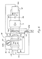
- the converter shown in Figure 5 overcomes this drawback. Like the converter of FIG. 1, it is intended to equip a timepiece, and it comprises a spring 1 driving, via a gear train 4, the rotor 3 of an energy generator electric which is designated, in this case, by the reference 30, and hands 9 for displaying the time.
- the spring 1, the gear train 4 and the needles 9 have not been shown in this figure 5.
- the rotor 3 is identical to that of the generator 2 in FIG. 1 and, like the latter, it is symbolized by l magnet 3a which is part of it.
- the generator 30, which is represented diagrammatically, has a structure which makes it resemble the motor described in patent US-A-4 371 821. Like this motor, the generator 30 comprises a stator 31 comprising three pole pieces 32, 33 and 34 .
- the first ends of these pole pieces 32, 33 and 34 are separated from each other by air gaps 35, 36 and 37 and delimit a substantially cylindrical space in which the permanent magnet 3a of the rotor 3 is disposed.
- the second end of the pole piece 32 is connected to the second end of the pole piece 33 by a frame 38 and to the pole piece 34 by a frame 39.
- Two coils 40 and 41 are respectively arranged on the frames 38 and 39.
- the generator 30 in FIG. 5 does not have any means for positioning the rotor 3.
- the converter of FIG. 5 comprises a rectifier 7, similar to that of FIG. 1, the input of which is connected to the terminals 40a and 40b of the coil 40 and the output of which is connected to a storage and filtering capacitor 8, also similar to that in Figure 1.
- the speed of rotation of the rotor 3 of the generator 30 is regulated by a circuit which includes braking means 11 'and a control circuit 12 of these braking means 11' which is identical, in this example, to circuit 12 in the figure 1 and which has therefore not been shown in detail again.
- the input and output of this circuit 12, designated by 12a and by 12b in FIG. 5, correspond respectively to the input of the forming circuit 28 and to the output Q of the flip-flop 23 of FIG. 1.
- the braking means 11 ′ comprise a resistor 13 and a transmission door 14 connected, in series with each other, to the terminals 40a and 40b of the coil 40.
- This resistor 13 and this door 14 are similar to those of Figure 1.
- the braking means 11 'further include a transmission door 42 connected directly to the terminals 41 a and 41 b of the coil 41.
- the control electrode 42a of this door 42 is connected, like the control electrode 14a of the gate 14, at the output 12b of the control circuit 12.
- Terminal 41a of coil 41 is connected to terminal 40a of coil 40, the potential of which is taken as the reference potential of the circuit.
- the transmission door 42 therefore responds as the transmission door 14 to the signal produced by the control circuit 12. When this signal is in the logic state "0", these two doors 14 and 42 are blocked, and when it is in logic state "1", they are conductive.
- the input 12a of the control circuit 12 is connected to the terminal 40b of the coil 40.
- the coil 40 therefore plays the same role as the coil 6 of the converter of FIG. 1. It provides in particular the electrical energy intended to supply the circuit 12 and the other possible circuits, and the voltage present at its terminal 40b is used by this circuit 12 to determine the instants when the rotor 3 passes through its zero position.
- the magnetic coupling factor of the magnet 3a with the coil 40 has a variation as a function of the angular position of the rotor 3 which is, at least as a first approximation, identical to that of the coupling factor C1 in the case of FIG. 1
- the angular positions where this coupling factor is zero are close to those where the direction of the axis of magnetization of the magnet 3a makes an angle of 60 ° approximately with the straight line passing through the middle of the air gap 35 and through the axis of rotation of the rotor 3.
- One of these two positions is the zero position of the rotor 3 defined above.
- the magnet 3a is obviously also magnetically coupled to the coil 41.
- the coupling factor C2 of this magnet 3a and of this coil 41 has a variation similar to that of the factor C1, but with zero values which are close to the angular positions of the rotor 3 where the direction of the magnetization axis of the magnet 3a makes an angle of approximately 60 ° with the straight line passing through the middle of the air gap 36 and through the axis of rotation of the rotor 3.
- the rotor 3a is therefore effectively braked whatever its angular position, and its instantaneous speed, when it is braked, no longer exhibits the significant variations which it exhibited in the case of FIG. 1.
- the set speed Vc can therefore be chosen to an even lower value than in the case of FIG. 1, which correspondingly reduces the mechanical and magnetic losses in the converter and therefore increases its efficiency.
- the counting capacity of the counters 22 and 25 as well as, if necessary, the frequency of the signal supplied by the oscillator 21 must of course be adapted to the chosen target speed.
- control circuit 12 ′ in FIG. 4 can also be used in a converter equipped with the generator 30 in FIG. 5. This variant will not be described here.
- FIG. 6 represents the diagram of a control circuit 12 "of the braking means 11 which can be used in place of the circuit 12 in the converter of FIG. 5.
- the counters 22 and 25 of circuit 12 are replaced by 22" and 25 "counters each comprising twelve flip-flops.
- the counting capacity of these 22" and 25 "counters is therefore only 4096
- the comparator 24 of circuit 12 is of course replaced by a comparator 24 "having twelve first and twelve second inputs, also designated respectively by A and B.
- the formatter 28 of circuit 12 is replaced by a formator 28" whose output delivers a pulse each time the voltage across the coil 40 passes through zero in one direction or the other, that is to say twice per revolution of the rotor 3.
- the trainer 28 “comprises, in this example, an amplifier 28.1, a capacitor 28.2 and a resistor 28.3 similar to the elements bearing the same references in FIG. 1, an inverter 28.4 a second capacitor 28.5, a second resistor 28.6 and an OR gate 28.7 All of these are connected to each other as shown.
- circuit 12 is similar to the components of circuit 12 having the same references.
- the generator 30 supplies electrical energy to each half-turn of the rotor 3.
- the braking of the rotor 3 during the part of the period of the reference signal where it must be braked is however effective since the coupling factor C2 of the magnet 3a with the coil 41 reaches a high value during this part of this period.
- the reference speed Vc of the rotor 3 could therefore be chosen at a lower value than four revolutions per second. It would of course be necessary, in such a case, to adapt the various components of the converter accordingly, in particular the oscillator 21 and / or the counter 22 "so that the period of the reference signal has a value corresponding to the chosen reference speed.
- the coil 41 could be connected to the input of a rectifier, similar to rectifier 7, the output of which would also be connected to the capacitor of storage 8. In this embodiment, which has not been shown, the coil 41 would therefore also supply electrical energy to the capacitor 8.
- the average speed Vt of the rotor 3 during a period of the reference signal starting at an instant t0 is adjusted by modifying by a fixed duration, at this instant t0, the time T2 or T2 'during which the rotor 3 will not be braked during this period, the direction of this modification being determined by the direction of the difference between the actual angular position of the rotor 3 at this time t0 and its zero position.
- the average speed Vt of the rotor 3 during each period of the reference signal is simply adjusted as a function of the direction of the difference between the average speed Vt during the previous period and the reference speed Vc.
- This adjustment mode has the advantage of being particularly simple to implement. However, depending on the type of converter in which it is used, and in particular according to the mechanical characteristics of the various moving elements of this converter and the electrical and magnetic characteristics of its generator 2, this mode of adjustment is not always the best. adapted.
- the speed of the adjustment that is to say the speed with which the average speed Vt is brought back to a value close to the speed of reference Vc after having deviated considerably from it for any reason, can also be low.
- this increase in the speed of adjustment can however cause instability of the speed Vt which can start to oscillate with a relatively large amplitude around the reference speed Vc.
- This adjustment mode can advantageously be implemented in practically any type of converter because the influence of each of the pieces of information that it uses on the value of the modification imposed at time T2 or T2 'can be adapted as a function of the characteristics of the converter so as to ensure great speed in adjusting the speed Vt while virtually eliminating any risk of excessive oscillation of this speed Vt around the set speed Vc.
- the mean speed of the rotor is regulated by adjusting, during each period of the reference signal, the duration during which it rotates at a speed higher than the setpoint speed as a function of the more or less direct measurement, made at the start of this period, of its average speed during the preceding period of the reference signal. It is obvious that this regulation can also be ensured by adjusting, during each period of the reference signal, the duration during which the rotor turns at a speed lower than the set speed according to the same comparison. Embodiments of converters according to the invention making use of this possibility have not been shown because they are easily deduced from those which have been described above.
- the counter 25, 25 'or 25 "which determines the duration of the time T2 or T2' can be designed so its content automatically takes on a predetermined value at the moment when, after switching on the converter, the voltage across the terminals of the capacitor 8 reaches a value sufficient for the electronic circuits which it supplies to function properly.
- This predetermined value may be equal, for example, half the maximum value that the contents of this 25, 25 'or 25 "counter can take.
- the rotor 3 rotates continuously, sometimes at high speed, sometimes at low speed.
- the setpoint speed Vc cannot therefore be chosen at an arbitrarily low value.
- the minimum value that can be chosen is around two to three revolutions per second.
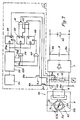
- FIG. 7 represents the diagram of a converter in which the reference speed Vc of the rotor 3 can be chosen at a value practically as low as desired. In the example of this figure 7, this value was chosen at 0.5 revolutions per second.
- the converter of FIG. 7 comprises, like those which have been described above, a source of mechanical energy constituted by a barrel spring, which is similar to those of the preceding converters and which has therefore not been shown.
- This barrel spring is connected, via a gear train, also not shown, to the rotor 3 of a generator 50.
- This rotor 3 is also similar to the rotors of the generators of the previous converters, and like those Ci, it is symbolized by the permanent magnet 3a which is part of it.
- the generator 50 differs from the generator 2 in FIG. 1 only by the presence of two notches 51 and 52 which are formed in the wall of the pole shoes which surround the magnet 3a and which are diametrically opposite one another.
- positioning torque which is exerted on the rotor 3 and which has a substantially sinusoidal variation as a function of the angular position of the rotor. 3, with a period equal to 180 °, that is to say a half-turn of the rotor 3.
- This positioning torque has been shown in FIG. 8 with the reference CP.
- the torque CP tends to rotate the rotor 3 in the increasing direction of the angle X when it is represented as positive in FIG. 8, and in the decreasing direction of the angle X when it is represented as negative.
- the same convention will be used for the representation of the other couples which will be described later.
- positions CP1 and CP2 are those for which the magnetization axis of the magnet 3a of the rotor 3 has a direction substantially perpendicular to the straight line joining the middle of the notches 51 and 52.
- the straight line joining the middle of the notches 51 and 52 makes an angle of 10 ° with the straight line taken as the origin of the angles X.
- this straight line taken as the origin of the angles X is perpendicular to the straight line joining the middle of air gaps 5a and 5b.
- the two stable equilibrium positions CP1 and CP2 of the rotor 3 are therefore those where the magnetization axis of the magnet 3a makes an angle of 80 ° with the origin of the angles X and an angle of 90 ° with the straight line joining the middle of the notches 51 and 52.
- the rotor 3 is also subjected to the mechanical motor torque transmitted by the gear train 4 which connects it to the spring 1.
- the various components of the converter are chosen so that the maximum value of this mechanical torque is less than the maximum value of the positioning torque CP.
- the variation of the torque CR is periodic, with a period equal to 180 °. Since, in addition, the maximum value of the mechanical torque CM is less than the maximum value of the torque CP, the torque CR has, on one revolution of the rotor, four zero values, two of which, separated by an angle of 180 °, correspond to positions d stable equilibrium and the other two, also separated by an angle of 180 °, correspond to unstable equilibrium positions of the rotor 3. In FIG. 8, the two stable equilibrium positions have been designated by P1 and P2 and the two positions of unstable equilibrium have been designated by P3 and P4.
- the converter of FIG. 7 comprises braking means 11, a rectifier 7 and a capacitor 8 similar to those of FIG. 1 and which will not be described again here.
- the converter of FIG. 7 also includes a circuit 53 for controlling the braking means 11.
- This circuit 53 includes an oscillator 54 which delivers a signal in the form of pulses having a frequency of 32,768 Hz for example.
- the output of the oscillator 54 is connected to the input of a counter 55 composed of fifteen flip-flops which have not been shown separately. These fifteen flip-flops are connected to each other in a cascade in a conventional manner, so that the counting capacity of the counter 55 is equal to 32,768.
- the counter 55 has an output 55a constituted by the inverse output of the fifteenth of the above flip-flops and which therefore delivers a signal having a period of 1 second.
- This output 55a is connected to the clock inputs Ck of three flip-flops 56, 57 and 58, all three of type T.
- the counter 55 further comprises outputs 55b, 55c and 55d which are constituted by the direct outputs of its fifth, seventh and eighth flip-flops. These outputs 55b, 55c and 55d therefore deliver signals having frequencies of 2048 Hz, 256 Hz and 128 Hz respectively.
- the outputs 55b, 55c and 55d of the counter 55 are connected to the inputs of an AND gate 59 whose output is connected to the reset input R of the flip-flop 56.
- the outputs 55b and 55c of the counter 55 are connected to the inputs of another AND gate 60 whose output is connected to the reset input R of the flip-flop 58.
- the output Q of the flip-flop 56 is connected to the control electrode 14a of the transmission door 14.
- the outputs Q of the flip-flops 57 and 58 are connected to the inputs of a NAND gate 61 whose output is connected to the control electrode of a P-type MOS transistor designated by Tr1.
- the output Q of the flip-flop 58 is further connected to an input of an AND gate 62 having a second input connected to the output Q of the flip-flop 57.
- the output of the gate 62 is connected to the control electrode an N-type MOS transistor designated by Tr2.
- the drains of the transistor Tr1 and Tr2 are connected, together, to the terminal 6b of the coil 6 and their sources are connected respectively to the terminals 8b and 8a of the capacitor 8.
- the connections of these sources with these terminals have not been shown.
- these terminals 8a and 8b respectively constitute the negative and positive terminals of the supply of the circuit.
- the output 55a of the counter 55 delivers a signal having a period of 1 second which will later be shown to constitute a reference signal comparable to the reference signals described above.
- the instants when this signal 55a goes to state "1" will be designated by t0, as above.
- the output Q of the flip-flop 58 is in the state "0".
- the outputs of the gates 61 and 62 are therefore respectively in the state “1” and in the state "0", and the two transistors Tr1 and Tr2 are blocked.
- the coil 6 is shaped and arranged on the stator 5 so that when its terminal 6b is connected to the positive pole of the power supply, in a manner which will be described later, it creates a magnetic field which causes the rotation of the rotor 3 in the positive direction of the angle X when this rotor 3 is in its stable equilibrium position P1.
- the magnetic field created by this coil 6 causes the rotation of the rotor 3 also in the positive direction of the angle X, but when this rotor 3 is in its stable equilibrium position P2.
- the output 55a of the counter 55 goes to state "1".
- the outputs 55b, 55c and 55d of this counter 55 pass to the state "0".
- the inputs R of the flip-flops 56 and 58 therefore pass to the "O” state.
- the Q output of the flip-flop 56 therefore goes to the "O” state, which blocks the transmission gate 14, and the Q outputs of the flip-flop 57 and 58 go to the "1" state.
- the blocking of the transmission door 14 is not sufficient to cause the rotation of the rotor 3, since the latter is only subjected to the torque CR which tends to maintain it in the position P1.
- the transistor Tr1 is made conductive by the state "0" which appears at the output of the gate 61.
- the terminal 6b of the coil 6 is therefore connected to the positive pole of the power supply to the circuit, and a current begins to flow in this coil 6, in the direction of arrow 1.
- the magnetic field produced by this current causes the rotor to rotate in the increasing direction of the angle X.
- the generator 50 therefore operates, immediately after time t01, like a motor.
- the transistor Tr is therefore blocked by the state "1" which appears at the output of the gate 61, and the current flowing in the coil 6 is interrupted.
- the characteristics of the generator 50 and the duration of the time T3 separating the instants t01 and t31 have been chosen so that the rotor 3 is close to its unstable equilibrium position P3 at the instant t31 and that, if there is n has not reached this position P3 at this time, its kinetic energy is sufficient for it to reach and exceed it.
- the rotor 3 which is at this instant t41 in an intermediate position Pf1 situated between its unstable equilibrium point P3 and its stable equilibrium point P2, is therefore braked, and its speed decreases sharply. It continues to rotate at slow speed in response to the torque CR which decreases and which is canceled when the rotor 3 reaches its second stable equilibrium position P2. The rotor 3 therefore stops in this position P2, after having made some oscillations around it.
- the terminal 6b of the coil 6 is therefore connected, this time, to the negative pole of the power supply, and a current begins to flow in this coil 6, in the opposite direction to the arrow 1.
- the field produced by this current causes the rotor 3 to rotate again in the direction of the increasing angle X.
- the generator 50 therefore functions again as a motor.
- the output of gate 60 goes to state "1" after a time T3, at a time situated approximately 2.2 milliseconds after time t02 and designated by t32.
- the output Q of the flip-flop 58 therefore returns to the “0” state, which causes the transistor Tr2 to block.
- the rotor 3 continues its rotation under the influence of its kinetic energy and the torque CR for a time T4, until the output of the gate 59 changes to the state "1", at a moment designated by t42 and located approximately 3.8 milliseconds after time t32 when the rotor 3 is in an intermediate position Pf2 located between its positions P4 and P1.
- the average speed of rotation of the rotor 3 is indeed equal to the set speed Vc which has been chosen, ie in this example 0.5 revolutions per second.
- the period of the reference signal is equal to the ratio between a predetermined angle of rotation of the rotor, 180 °, and the reference speed Vc.
- the factor k mentioned above is therefore equal to 0.5, as in the case of FIG. 5.
- this average speed is independent of the time actually taken by the rotor 3 to turn around, provided of course that this time is not greater than the period of the reference signal produced by the output 55a of the counter 55 .
- the average speed of the rotor 3 only depends on the period of the reference signal. In a timepiece without a second hand, it would therefore be possible to choose a value even lower than 0.5 revolutions per second for this average speed.
- the capacity of the storage capacitor 8 must be all the greater when this average speed is low. This capacitor 8 must in fact supply the various electronic elements throughout the time which separates two supplies of electrical energy by the generator 50, without the voltage at its terminals varying too much.
- the volume of a capacitor being proportional to its capacity, it may prove impossible to choose a very low value for the reference speed Vc, the capacitor 8 then necessary being too bulky to enter a timepiece such that, for example, a wristwatch.
- the generator 50 operates as a stepping motor. It receives from the storage capacitor 8 a certain amount of electrical energy, which it transforms, with a certain efficiency, into mechanical energy which it uses to rotate its rotor from its position P1 or P2, to its position P3 or , respectively, P4.
- the magnitude of this mechanical energy is proportional to the area of each of the zones Z1 delimited by the X axis and the negative part of the curve CR in FIG. 8.
- the rotor 3 of the generator 50 rotates at high speed under the influence of the torque CR.
- the generator 50 therefore produces a certain amount of electrical energy, like the generators 2 and 30 of FIGS. 1 and 5. This amount of energy produced is substantially proportional to the surface of each of the zones Z2 delimited by the X axis and the positive part of the CR curve in Figure 8, between points P3 and Pf1 1 or P4 and Pf2.
- the generator 50 still produces a certain amount of electrical energy, but this energy is dissipated in the resistor 13, which causes braking of the rotor 3.
- the rotor 3 then remains stationary until the time t0 following when the process described above start again.
- the converter When the spring 1 is wound up, after such a stop, the converter does not start to operate again if adequate means are not provided for this purpose, since the mechanical motor torque applied by the spring 1 to the rotor 3 via the train 4 is less than the positioning torque created by the notches 51 and 52, and that no more electrical energy is available in the capacitor 8 to overcome this positioning torque.
- the means required to restart the converter can be mechanical in nature. They can for example be constituted by a clutch responding to a rapid rotation of a control rod, such as the time-setting rod of the watch, for connecting this control rod to the rotor 3.
- These means can also be of an electrical nature. They can for example be constituted by a photoelectric cell connected in parallel with the capacitor 8 and capable of charging the latter when it receives a sufficient quantity of light.
- Such a cell has been represented in FIG. 7, in dotted lines, with the reference 63.
- the rotor of the generator has a single permanent magnet having only one pair of magnetic poles.
- the voltage produced by this generator therefore has a full period for each revolution of the rotor.
- the period of the reference signal is equal to the ratio between a predetermined angle of rotation of the rotor and the set speed Vc, this predetermined angle being equal to k ⁇ 360 ° with preferably, k equal to 0.5 or to a whole number equal to or greater than 1.
- the permanent magnet of the generator rotor can comprise not one but p pairs of magnetic poles, with p integer.
- the voltage produced by the generator therefore has p periods per revolution of the rotor.
- the predetermined angle mentioned above is then obviously equal to k ⁇ 360 ° / p, the period of the reference signal always having to be equal to the ratio between this predetermined angle and the set speed.
- the generator rotor does not have a single permanent magnet but, like the generator rotor described in patent CH-B-597,636 mentioned above, a plurality of magnets arranged at the periphery of 'a rotating disc. In such a case, the number p above is obviously equal to half the number of these magnets.
- a generator according to the invention may also not include a stator for magnetically coupling its magnet (s) to its coil (s).
- the capacitor 8 for storing electrical energy can be replaced without difficulty by a rechargeable accumulator.
Claims (8)
dadurch gekennzeichnet, daß die genannten Mittel (23 bis 28; 23, 24', 25', 26 bis 29; 23, 24", 25" 26, 27, 28"; 56, 59) für das Erzeugen des Steuersignals Mittel (23, 56) umfassen zum Versetzen des Steuersignals in einen der genannten Zustände bei jedem Zeitpunkt einer Mehrzahl von ersten Zeitpunkten, die einander periodisch folgen mit einer Periode gleich derjenigen des Referenzsignals, sowie Mittel (24 bis 28; 24', 25', 26 bis 29; 24", 25", 26, 27, 28"; 59) zum Versetzen des Steuersignals in den ändern der genannten Zustände bei zweiten Zeitpunkten, die jeweils von dem unmittelbar vorangehenden ersten Zeitpunkt durch ein Zeitintervall getrennt sind, das eine Dauer hat, die kleiner als die Periode des Referenzsignals ist.
Applications Claiming Priority (2)
| Application Number | Priority Date | Filing Date | Title |
|---|---|---|---|
| CH124786A CH665082GA3 (de) | 1986-03-26 | 1986-03-26 | |
| CH1247/86 | 1986-03-26 |
Publications (2)
| Publication Number | Publication Date |
|---|---|
| EP0239820A1 EP0239820A1 (de) | 1987-10-07 |
| EP0239820B1 true EP0239820B1 (de) | 1989-10-18 |
Family
ID=4205921
Family Applications (1)
| Application Number | Title | Priority Date | Filing Date |
|---|---|---|---|
| EP87103046A Expired EP0239820B1 (de) | 1986-03-26 | 1987-03-04 | Umformer von mechanischer in elektrische Energie |
Country Status (4)
| Country | Link |
|---|---|
| EP (1) | EP0239820B1 (de) |
| JP (1) | JPH07119812B2 (de) |
| CH (1) | CH665082GA3 (de) |
| DE (1) | DE3760835D1 (de) |
Cited By (13)
| Publication number | Priority date | Publication date | Assignee | Title |
|---|---|---|---|---|
| EP0695978A1 (de) | 1994-08-03 | 1996-02-07 | Seiko Instruments Inc. | Elektronische Kontrolluhr |
| US5751666A (en) * | 1996-08-01 | 1998-05-12 | Asulab S.A. | Electronic timepiece comprising a generator driven by a spring barrel |
| US5881027A (en) * | 1995-09-07 | 1999-03-09 | Schafroth; Konrad | Timepiece movement |
| US6041021A (en) * | 1997-09-30 | 2000-03-21 | Seiko Epson Corporation | Electronically controlled mechanical timepiece and control method therefor |
| US6097675A (en) * | 1997-09-26 | 2000-08-01 | Seiko Epson Corporation | Electronically controlled mechanical timepiece |
| US6113259A (en) * | 1997-04-28 | 2000-09-05 | Asulab S.A. | Electronic timepiece supplied by a generator driven by a mechanical power source |
| US6194878B1 (en) | 1997-06-25 | 2001-02-27 | Conseils Et Manufactures Vlg Sa | Electronic speed control circuit |
| US6373788B1 (en) | 1998-11-17 | 2002-04-16 | Seiko Epson Corporation | Electronically controlled mechanical timepiece |
| US6373789B2 (en) | 1997-09-30 | 2002-04-16 | Seiko Epson Corporation | Electronically controlled mechanical timepiece and method controlling the same |
| US6477116B1 (en) | 1997-09-30 | 2002-11-05 | Seiko Epson Corporation | Rotation controller and rotation control method |
| US6483276B1 (en) | 1999-03-03 | 2002-11-19 | Seiko Epson Corporation | Electronic device with variable chopping signal and duty ratio selection for strong braking |
| US6603236B2 (en) | 1998-01-22 | 2003-08-05 | Seiko Epson Corporation | Electronic timepiece |
| US6744699B2 (en) | 2001-07-02 | 2004-06-01 | Richemont International Sa | Electronic regulation module for the movement of a mechanically wound watch |
Families Citing this family (12)
| Publication number | Priority date | Publication date | Assignee | Title |
|---|---|---|---|---|
| JP2652057B2 (ja) * | 1988-01-25 | 1997-09-10 | セイコーエプソン株式会社 | 発電装置 |
| DE3903706A1 (de) * | 1988-02-09 | 1989-08-17 | Fraunhofer Ges Forschung | Uhr mit einem elektronischen uhrenbaustein |
| US6169709B1 (en) | 1995-09-07 | 2001-01-02 | Konrad Schafroth | Watch movement |
| CH690523A5 (fr) * | 1996-12-09 | 2000-09-29 | Asulab Sa | Pièce d'horlogerie comportant une génératrice d'énergie électrique. |
| DE69712034T2 (de) * | 1997-04-28 | 2002-11-21 | Asulab Sa | Elektronisches Uhrwerk gespeist von einem Generator, der durch eine mechanische Energiequelle angetrieben wird |
| US6795378B2 (en) | 1997-09-30 | 2004-09-21 | Seiko Epson Corporation | Electronic device, electronically controlled mechanical timepiece, and control method therefor |
| WO2000029910A1 (fr) * | 1998-11-17 | 2000-05-25 | Seiko Epson Corporation | Piece d'horlogerie mecanique a commande electronique |
| JP2002281684A (ja) * | 2001-01-11 | 2002-09-27 | Seiko Epson Corp | 弱電用発電装置 |
| US6826124B2 (en) * | 2002-12-04 | 2004-11-30 | Asulab S.A. | Timepiece with power reserve indication |
| ATE555428T1 (de) | 2009-06-16 | 2012-05-15 | Eta Sa Mft Horlogere Suisse | Kleiner elektromechanischer signalwandler, insbesondere uhrgenerator |
| CH707005B1 (fr) | 2012-09-25 | 2023-02-15 | Richemont Int Sa | Mouvement de montre-chronographe avec barillet et régulateur à quartz. |
| CH707340A2 (fr) * | 2012-12-11 | 2014-06-13 | Richemont Internat Ltd | Organe régulateur pour montre-bracelet. |
Family Cites Families (7)
| Publication number | Priority date | Publication date | Assignee | Title |
|---|---|---|---|---|
| DE2118057C3 (de) * | 1971-04-14 | 1975-01-09 | Forschungsgesellschaft Fuer Uhrenund Feingeraete-Technik E.V., 7000 Stuttgart | Zeithaltendes Gerät mit einem von einem Antriebsmotor angetriebenen Anzeigesystem, dessen Stand periodisch korrigiert wird |
| US3756014A (en) * | 1971-05-18 | 1973-09-04 | Timex Corp | Synchronized quartz crystal watch |
| DE2125224C3 (de) * | 1971-05-21 | 1980-12-18 | Forschungsgesellschaft Fuer Uhren- Und Feingeraetetechnik E. V., 7000 Stuttgart | Vorrichtung zur Korrektur des Ganges eines zeithaltenden Gerätes |
| BE789976A (fr) * | 1971-10-15 | 1973-02-01 | Centre Electron Horloger | Garde-temps |
| ES430659A1 (es) * | 1973-10-24 | 1976-11-01 | Jauch | Un procedimiento y un dispositivo para la sincronizacion deun sistema oscilante accionado por un acumulador mecanico deenergia, en especial de un reloj. |
| JPS5377560A (en) * | 1976-09-16 | 1978-07-10 | Seiko Epson Corp | Electronic wristwatch |
| JPS59135388A (ja) * | 1983-01-25 | 1984-08-03 | Seiko Epson Corp | 時計 |
-
1986
- 1986-03-26 CH CH124786A patent/CH665082GA3/fr unknown
-
1987
- 1987-03-04 EP EP87103046A patent/EP0239820B1/de not_active Expired
- 1987-03-04 DE DE8787103046T patent/DE3760835D1/de not_active Expired
- 1987-03-26 JP JP62070521A patent/JPH07119812B2/ja not_active Expired - Fee Related
Cited By (18)
| Publication number | Priority date | Publication date | Assignee | Title |
|---|---|---|---|---|
| EP0695978B1 (de) * | 1994-08-03 | 2001-12-12 | Seiko Instruments Inc. | Elektronische Kontrolluhr |
| US5615178A (en) * | 1994-08-03 | 1997-03-25 | Seiko Instruments Inc. | Electronic control timepiece |
| EP0695978A1 (de) | 1994-08-03 | 1996-02-07 | Seiko Instruments Inc. | Elektronische Kontrolluhr |
| US5881027A (en) * | 1995-09-07 | 1999-03-09 | Schafroth; Konrad | Timepiece movement |
| US5751666A (en) * | 1996-08-01 | 1998-05-12 | Asulab S.A. | Electronic timepiece comprising a generator driven by a spring barrel |
| US6113259A (en) * | 1997-04-28 | 2000-09-05 | Asulab S.A. | Electronic timepiece supplied by a generator driven by a mechanical power source |
| US6194878B1 (en) | 1997-06-25 | 2001-02-27 | Conseils Et Manufactures Vlg Sa | Electronic speed control circuit |
| US6208119B1 (en) | 1997-06-25 | 2001-03-27 | Conseils Et Manufactures Vlg Sa | Electronic speed-control circuit |
| US6097675A (en) * | 1997-09-26 | 2000-08-01 | Seiko Epson Corporation | Electronically controlled mechanical timepiece |
| US6041021A (en) * | 1997-09-30 | 2000-03-21 | Seiko Epson Corporation | Electronically controlled mechanical timepiece and control method therefor |
| US6252828B1 (en) | 1997-09-30 | 2001-06-26 | Seiko Epson Corporation | Electronically controlled mechanical timepiece and control method therefor |
| US6373789B2 (en) | 1997-09-30 | 2002-04-16 | Seiko Epson Corporation | Electronically controlled mechanical timepiece and method controlling the same |
| US6477116B1 (en) | 1997-09-30 | 2002-11-05 | Seiko Epson Corporation | Rotation controller and rotation control method |
| USRE38110E1 (en) | 1997-09-30 | 2003-05-06 | Seiko Epson Corporation | Electronically controlled mechanical timepiece and control method therefor |
| US6603236B2 (en) | 1998-01-22 | 2003-08-05 | Seiko Epson Corporation | Electronic timepiece |
| US6373788B1 (en) | 1998-11-17 | 2002-04-16 | Seiko Epson Corporation | Electronically controlled mechanical timepiece |
| US6483276B1 (en) | 1999-03-03 | 2002-11-19 | Seiko Epson Corporation | Electronic device with variable chopping signal and duty ratio selection for strong braking |
| US6744699B2 (en) | 2001-07-02 | 2004-06-01 | Richemont International Sa | Electronic regulation module for the movement of a mechanically wound watch |
Also Published As
| Publication number | Publication date |
|---|---|
| JPH07119812B2 (ja) | 1995-12-20 |
| EP0239820A1 (de) | 1987-10-07 |
| CH665082GA3 (de) | 1988-04-29 |
| DE3760835D1 (en) | 1989-11-23 |
| JPS62255889A (ja) | 1987-11-07 |
Similar Documents
| Publication | Publication Date | Title |
|---|---|---|
| EP0239820B1 (de) | Umformer von mechanischer in elektrische Energie | |
| EP0679968B1 (de) | Uhr mit mechanischem Antrieb und mit elektronischer Steuerung | |
| EP0103542B1 (de) | Schrittmotor | |
| EP1521141B1 (de) | Uhr mit einem mechanischen Uhrwerk, das mit einem elektronischen Regulator gekoppelt ist | |
| EP0806710B2 (de) | Stabilisation einer elektronischen Schaltung zur Regelung des mechanischen Gangwerks einer Zeitmessvorrichtung | |
| FR2529032A1 (fr) | Procede d'alimentation d'un moteur pas a pas monophase pour piece d'horlogerie | |
| EP0161582B1 (de) | Schrittmotoranordnung | |
| CH690523A5 (fr) | Pièce d'horlogerie comportant une génératrice d'énergie électrique. | |
| EP0077293B1 (de) | Verfahren und Vorrichtung zur Steuerung eines Schrittmotors in einem Uhrwerk | |
| EP0253153B1 (de) | Verfahren und Vorrichtung zur Kontrolle eines Schrittmotors | |
| EP0135104B1 (de) | Verfahren und Vorrichtung zum Ansteuern eines Schrittmotors | |
| EP0320754B1 (de) | Vorrichtung mit einer Photozelle zum Wiederaufziehen der Zugfeder | |
| EP0217164B1 (de) | Elektronisches Uhrwerk mit analoger Anzeige, die ein Sekunden anzeigendes Organ enthält | |
| EP0875807B1 (de) | Elektronisches Uhrwerk gespeist von einem Generator, der durch eine mechanische Energiequelle angetrieben wird | |
| EP0982846B1 (de) | Verfahren und Vorrichtung zur Regelung eines Schrittmotors | |
| EP0250862B1 (de) | Verfahren und Vorrichtung zum Steuern eines Schrittmotors | |
| EP0108711B1 (de) | Verfahren und Vorrichtung zur Steuerung eines Schrittmotors | |
| EP0848306B1 (de) | Zeitmessgerät mit einem Generator zur Erzeugung elektrischer Energie | |
| EP0155661B1 (de) | Regelschaltung für einen Schrittmotor | |
| CH672572B5 (de) | ||
| CH495005A (fr) | Pièce d'horlogerie électrique comportant un ensemble balancier-spiral commandé par un transducteur | |
| EP0028433B1 (de) | Antriebsvorrichtung für ein Gerät, welches eine Schrittschaltung benötigt | |
| FR2700428A1 (fr) | Circuit de commutation d'un moteur à courant continu sanc collecteur et moteur à courant continu sans collecteur muni d'un tel circuit. | |
| EP0190591A1 (de) | Motorwerk geeignet für hohe Geschwindigkeit | |
| EP0484770B1 (de) | Verfahren zur Steuerung eines Schrittmotors und Vorrichtung zur Durchführung dieses Verfahrens |
Legal Events
| Date | Code | Title | Description |
|---|---|---|---|
| PUAI | Public reference made under article 153(3) epc to a published international application that has entered the european phase |
Free format text: ORIGINAL CODE: 0009012 |
|
| AK | Designated contracting states |
Kind code of ref document: A1 Designated state(s): CH DE FR GB LI |
|
| 17P | Request for examination filed |
Effective date: 19871019 |
|
| 17Q | First examination report despatched |
Effective date: 19890301 |
|
| GRAA | (expected) grant |
Free format text: ORIGINAL CODE: 0009210 |
|
| AK | Designated contracting states |
Kind code of ref document: B1 Designated state(s): CH DE FR GB LI |
|
| REF | Corresponds to: |
Ref document number: 3760835 Country of ref document: DE Date of ref document: 19891123 |
|
| GBT | Gb: translation of ep patent filed (gb section 77(6)(a)/1977) | ||
| PLBE | No opposition filed within time limit |
Free format text: ORIGINAL CODE: 0009261 |
|
| STAA | Information on the status of an ep patent application or granted ep patent |
Free format text: STATUS: NO OPPOSITION FILED WITHIN TIME LIMIT |
|
| 26N | No opposition filed | ||
| REG | Reference to a national code |
Ref country code: GB Ref legal event code: IF02 |
|
| PGFP | Annual fee paid to national office [announced via postgrant information from national office to epo] |
Ref country code: CH Payment date: 20040225 Year of fee payment: 18 |
|
| PGFP | Annual fee paid to national office [announced via postgrant information from national office to epo] |
Ref country code: GB Payment date: 20040226 Year of fee payment: 18 |
|
| PGFP | Annual fee paid to national office [announced via postgrant information from national office to epo] |
Ref country code: DE Payment date: 20040305 Year of fee payment: 18 |
|
| PGFP | Annual fee paid to national office [announced via postgrant information from national office to epo] |
Ref country code: FR Payment date: 20040326 Year of fee payment: 18 |
|
| PG25 | Lapsed in a contracting state [announced via postgrant information from national office to epo] |
Ref country code: GB Free format text: LAPSE BECAUSE OF NON-PAYMENT OF DUE FEES Effective date: 20050304 |
|
| PG25 | Lapsed in a contracting state [announced via postgrant information from national office to epo] |
Ref country code: LI Free format text: LAPSE BECAUSE OF NON-PAYMENT OF DUE FEES Effective date: 20050331 Ref country code: CH Free format text: LAPSE BECAUSE OF NON-PAYMENT OF DUE FEES Effective date: 20050331 |
|
| PG25 | Lapsed in a contracting state [announced via postgrant information from national office to epo] |
Ref country code: DE Free format text: LAPSE BECAUSE OF NON-PAYMENT OF DUE FEES Effective date: 20051001 |
|
| REG | Reference to a national code |
Ref country code: CH Ref legal event code: PL |
|
| GBPC | Gb: european patent ceased through non-payment of renewal fee |
Effective date: 20050304 |
|
| PG25 | Lapsed in a contracting state [announced via postgrant information from national office to epo] |
Ref country code: FR Free format text: LAPSE BECAUSE OF NON-PAYMENT OF DUE FEES Effective date: 20051130 |
|
| REG | Reference to a national code |
Ref country code: FR Ref legal event code: ST Effective date: 20051130 |