EP0806631A1 - Capteur de vitesse angulaire et méthode pour sa fabrication - Google Patents
Capteur de vitesse angulaire et méthode pour sa fabrication Download PDFInfo
- Publication number
- EP0806631A1 EP0806631A1 EP97110803A EP97110803A EP0806631A1 EP 0806631 A1 EP0806631 A1 EP 0806631A1 EP 97110803 A EP97110803 A EP 97110803A EP 97110803 A EP97110803 A EP 97110803A EP 0806631 A1 EP0806631 A1 EP 0806631A1
- Authority
- EP
- European Patent Office
- Prior art keywords
- detector
- actuator
- angular velocity
- vibrator
- velocity sensor
- Prior art date
- Legal status (The legal status is an assumption and is not a legal conclusion. Google has not performed a legal analysis and makes no representation as to the accuracy of the status listed.)
- Granted
Links
Images


Classifications
-
- G—PHYSICS
- G01—MEASURING; TESTING
- G01C—MEASURING DISTANCES, LEVELS OR BEARINGS; SURVEYING; NAVIGATION; GYROSCOPIC INSTRUMENTS; PHOTOGRAMMETRY OR VIDEOGRAMMETRY
- G01C19/00—Gyroscopes; Turn-sensitive devices using vibrating masses; Turn-sensitive devices without moving masses; Measuring angular rate using gyroscopic effects
- G01C19/56—Turn-sensitive devices using vibrating masses, e.g. vibratory angular rate sensors based on Coriolis forces
- G01C19/5607—Turn-sensitive devices using vibrating masses, e.g. vibratory angular rate sensors based on Coriolis forces using vibrating tuning forks
Definitions
- the present invention relates to an angular velocity sensor known as a gyroscopic instrument and more particularly, to a high-performance angular velocity sensor having a tuning-fork construction where two vibrator units containing piezoelectric elements are coupled to each other and a method of fabricating the same.
- a conventional gyroscopic inertia navigation system includes mechanical rotor gyros for determining the direction of a moving object, e.g. an airplane or ship.
- an oscillator-type angular velocity sensor for detecting a "Coriolis force" with its detector while it is vibrating but not rotating.
- Such a sensor commonly employs a piezoelectric or electromagnetic oscillation mechanism.
- the detection of an angular velocity in the sensor is implemented by sensing a vibration torque of a frequency equal to that of the mass of a gyro which is not rotating but vibrating at a constant rate.
- the vibration torque is known as the Coriolis force generated when an angular velocity is involved.
- the oscillator-type angular velocity sensor can detect the amplitude of the vibration torque to determine an angular velocity.
- a variety of the oscillator-type angular velocity sensors employing piezoelectric elements have been introduced (for example, as depicted in the Proceeding of Japanese Institute of Aviation and Space, Vol.23, No.257, pp. 339-350).
- Fig. 5 which consists mainly of four piezoelectric bimorphous elements serving as an actuator, a monitor, and a first and a second detectors.
- the actuator 101 is orthogonally coupled by a joiner 105 to the first detector 103 constituting a first vibrator 109 while the monitor 102 is orthogonally coupled by another joiner 106 to the second detector 104 constituting a second vibrator 110.
- the first 109 and the second vibrators 110 are coupled to each other by a connector 107 which is supported at a point by a support 108, thus constructing a tuning-fork structure.
- the actuator 101 of piezoelectric bimorphous element When the actuator 101 of piezoelectric bimorphous element is loaded with a sine-wave voltage signal, its inverse piezoelectric effect causes the first vibrator 109 to vibrate. Then, the action of the tuning-fork structure results in vibration of the second vibrator 110.
- the monitor 102 of piezoelectric bimorphous element generates a charge on its surface through its piezoelectric action.
- the charge is proportional to the sine-wave voltage signal applied to the actuator 101.
- a constant, continuous action of vibration is developed by controlling the sine-wave voltage signal to the actuator 101 so that the charge generated by the monitor 102 remains uniform in the amplitude.
- Fig. 6 is a top view of the angular velocity sensor of Fig. 5.
- the turning movement at an angular velocity of ⁇ produces a Coriolis force on the first detector 103 which vibrates at a speed of v.
- the Coriolis force is at a right angle to the speed v and its magnitude is 2mv ⁇ (where m is the equivalent mass at the distal end of the first detector 103).
- the second detector 104 is responsive to vibrate at -v and a Coriolis force on the second detector 104 is -2mv ⁇ .
- the two detectors 103 and 104 are stressed in opposite directions by their respective Coriolis forces thus producing charges on the surface through their piezoelectric actions.
- the surface charge Q on the detectors 103 and 104 is expressed by: Q ⁇ a ⁇ sin ⁇ ⁇ t
- Q ⁇ ⁇ sin ⁇ ⁇ t the surface charge Q is found proportional to the angular velocity ⁇ and can be converted to a direct current signal through synchronous transaction at ⁇ o t.
- the angular velocity sensor is subjected to a translational movement rather than the rotation, its two detectors 103 and 104 produce two charges of the same polarity and their resultant DC signals are offset each other generating no output.
- the two signals derived from the unwanted charges are not always canceled to zero because of a symmetrical error and a difference in weight between the two, left and right, prongs of the tuning-fork structure of the conventional angular velocity sensor in which a plurality of piezoelectric bimorphous elements are assembled in a relatively complex manner and may not be identical in the quality.
- the piezoelectric element essentially includes two electrodes at both sides regardless of bimorphous or unimorphous type.
- the electrodes are commonly formed of silver materials printed onto both surfaces of a piezoelectric substance and thus, become rarely identical in weight, size, and quality due to the presence of unavoidable burrs impairing the symmetry of the tuning-fork structure.
- the angular velocity sensor according to the present invention has a tuning-fork structure comprising a first vibrator including a first actuator and a first detector joined orthogonally to each other, and a second vibrator including a second actuator and a second detector joined orthogonally to each other, the two vibrators being coupled by an electrode block to each other in parallel relationship along the axis of detection.
- the first and second detectors have a cross-sectionally four-sided plate shape accompanied with a piezoelectric element.
- the first vibrator is formed by bonding a piezoelectric detector element and a piezoelectric actuator element to two, upper and lower, parts of a metal base plate respectively which serve as the first detector and the first actuator and the second vibrator is formed by bonding a piezoelectric detector element and a piezoelectric actuator element to two, upper and lower, parts of a metal base plate respectively which serve as the second detector and the second actuator.
- the metal base plate is shaped by turning its two, upper and lower, parts in opposite directions through 90 degrees along a center line defined by two slits extending from both ends inwardly and crosswisely of said base plate so that the two, upper and lower, parts intersect at a right angle to each other.
- the grinding process is preferably executed by grinding off a part of one corner edge of the four-sided plate of the detector to form a beveled surface.
- a plurality of apertures may be provided in a specific region of the four-sided plate of the detector by radiation of a laser beam which contributes to the automatic action of the process.
- the angular velocity sensor provides improved thermal characteristics and prevents the generation of noise caused by external interruption or vibration.
- the vibrators are formed by bonding the piezoelectric element to the metal base plate of a particular shape and the electrodes of the piezoelectric element are arranged in a specific manner, the manufacture of the angular velocity sensor will be effected accurately and readily without creating any burrs and dust of the electrodes.
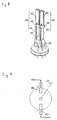
- Fig. 1 illustrates an angular velocity sensor of the present invention having a tuning-fork structure which comprises a first vibrator 4, a second vibrator 8, an electrode block 9 coupling the first 4 and the second vibrators 8 to each other, and a support pin 10 supporting at one point the electrode block 9.
- the first vibrator 4 includes a first eternally elastic metal plate 1 formed by turning its two, upper and lower, parts in opposite directions at center to intersect each other at a right angle, and a piezoelectric actuator 2 and a first piezoelectric detector 3 which are bonded to the two parts of the first eternally elastic metal plate 1 respectively.
- the second vibrator 8 includes a second eternally elastic metal plate 5 formed by turning its two regions parts in opposite directions at center to intersect each other at a right angle, and a piezoelectric monitor 6 and a second piezoelectric detector 7 which are bonded to the two parts of the second eternally elastic metal plate 5 respectively.
- the eternally elastic metal of this embodiment is elinvar alloy.
- the method of manufacture of the angular velocity sensor will now be described referring to the flow chart of Fig. 2.
- the first vibrator 4 and the second vibrator 8 assembled in the tuning-fork structure precisely or not, tend to produce their respective unwanted signals which cannot be offset to zero by each other because of a symmetrical error and a difference in weight between the two vibrators 4 and 8 of which piezoelectric elements are rarely identical in the quality. It is thus provided a trimming process explained later.
- the procedure of the method starts with an inspection process (1) for detecting unwanted signals representing the unbalancing factors of symmetrical error in the tuning-fork assembly (Step a).
- the unwanted signals detected in the inspection process are compared with a reference value L (Step b) and if the signals are smaller than L, the assembly is transferred to the next inspection process (2). If not, it is subjected to the trimming process for rough modification of its detector components (Step c). Then, unwanted signals on the modified detector elements are detected again (Step d) and compared with a reference value M (M>L) (Step e). If the unwanted signals are smaller than M, the assembly is transferred to a finish process. If not, it is subjected to the trimming process for fine modification of its detector component (Step f) .
- the assembly is returned to the inspection process (1) for re-examining the balance.
- the assembly accepted at the two inspection processes (1) and (2) is only transferred to the finish process.
- Fig 3 illustrates an angular velocity sensor of the present invention at which the trimming is executed by providing a plurality of apertures 11c in an edge region of the eternally elastic metal plate 5 of the detector component.
- the apertures 11c are formed with the use of a laser beam and are different in size for elimination of unwanted signals derived from a balancing error between the two vibrators. This technique allows the laser beam to be controlled to produce the apertures of desired size and/or depth appropriate to balance the tuning-fork assembly of the vibrators, increasing the efficiency of the trimming process.
- each of the first 1 and the second eternally elastic metal plates 5 is formed by turning two, upper and lower, parts of a metal plate through 90 degrees in opposite directions along a centre folding line defined by two crosswise slits extending inwardly from opposite ends to the centre, so that they intersect each other at a right angle.
- the folding lines 1a and 5a are located at a centre of the width and extends longitudinally from the centre, thus, contributing to the symmetry of the two vibrators.
Landscapes
- Physics & Mathematics (AREA)
- Engineering & Computer Science (AREA)
- General Physics & Mathematics (AREA)
- Radar, Positioning & Navigation (AREA)
- Remote Sensing (AREA)
- Gyroscopes (AREA)
Applications Claiming Priority (7)
| Application Number | Priority Date | Filing Date | Title |
|---|---|---|---|
| JP1605493 | 1993-02-03 | ||
| JP16054/93 | 1993-02-03 | ||
| JP1612293 | 1993-02-03 | ||
| JP1612293 | 1993-02-03 | ||
| JP16122/93 | 1993-02-03 | ||
| JP1605493 | 1993-02-03 | ||
| EP93111324A EP0611949B1 (fr) | 1993-02-03 | 1993-07-14 | Capteur de vitesse angulaire et méthode pour sa fabrication |
Related Parent Applications (2)
| Application Number | Title | Priority Date | Filing Date |
|---|---|---|---|
| EP93111324.5 Division | 1993-07-14 | ||
| EP93111324A Division EP0611949B1 (fr) | 1993-02-03 | 1993-07-14 | Capteur de vitesse angulaire et méthode pour sa fabrication |
Publications (2)
| Publication Number | Publication Date |
|---|---|
| EP0806631A1 true EP0806631A1 (fr) | 1997-11-12 |
| EP0806631B1 EP0806631B1 (fr) | 2001-11-07 |
Family
ID=26352303
Family Applications (2)
| Application Number | Title | Priority Date | Filing Date |
|---|---|---|---|
| EP93111324A Expired - Lifetime EP0611949B1 (fr) | 1993-02-03 | 1993-07-14 | Capteur de vitesse angulaire et méthode pour sa fabrication |
| EP97110803A Expired - Lifetime EP0806631B1 (fr) | 1993-02-03 | 1993-07-14 | Capteur de vitesse angulaire et méthode pour sa fabrication |
Family Applications Before (1)
| Application Number | Title | Priority Date | Filing Date |
|---|---|---|---|
| EP93111324A Expired - Lifetime EP0611949B1 (fr) | 1993-02-03 | 1993-07-14 | Capteur de vitesse angulaire et méthode pour sa fabrication |
Country Status (3)
| Country | Link |
|---|---|
| US (2) | US5445025A (fr) |
| EP (2) | EP0611949B1 (fr) |
| DE (2) | DE69318963T2 (fr) |
Families Citing this family (8)
| Publication number | Priority date | Publication date | Assignee | Title |
|---|---|---|---|---|
| US5698784A (en) * | 1996-01-24 | 1997-12-16 | Gyration, Inc. | Vibratory rate gyroscope and methods of assembly and operation |
| US6101878A (en) | 1997-03-24 | 2000-08-15 | Denso Corporation | Angular rate sensor and method of improving output characteristic thereof |
| US6571630B1 (en) | 1999-03-25 | 2003-06-03 | The Charles Stark Draper Laboratory, Inc. | Dynamically balanced microelectromechanical devices |
| JP2002243451A (ja) * | 2001-02-19 | 2002-08-28 | Matsushita Electric Ind Co Ltd | 角速度センサおよびその特性調整方法 |
| JP3791485B2 (ja) | 2002-06-04 | 2006-06-28 | 株式会社村田製作所 | 音叉形振動子およびそれを用いた振動ジャイロおよびそれを用いた電子装置および音叉形振動子の製造方法 |
| JP4163067B2 (ja) * | 2003-07-14 | 2008-10-08 | 日本碍子株式会社 | 物理量測定方法および装置 |
| US20050062362A1 (en) * | 2003-08-28 | 2005-03-24 | Hongyuan Yang | Oscillatory gyroscope |
| CN110375623B (zh) * | 2019-07-29 | 2021-05-28 | 重庆科技学院 | 一种磁响应柔性界面材料的滚动角测量装置及方法 |
Citations (7)
| Publication number | Priority date | Publication date | Assignee | Title |
|---|---|---|---|---|
| JPS5393792A (en) * | 1977-01-26 | 1978-08-17 | Seiko Instr & Electronics Ltd | Crystal vibrator |
| JPS5762612A (en) * | 1980-10-02 | 1982-04-15 | Seiko Epson Corp | Tuning fork quartz resonator |
| JPS57170897A (en) * | 1981-04-14 | 1982-10-21 | Citizen Watch Co Ltd | Manufacture of quartz oscillator |
| JPS5863212A (ja) * | 1981-10-13 | 1983-04-15 | Citizen Watch Co Ltd | 水晶振動子 |
| JPS6049215A (ja) * | 1983-08-30 | 1985-03-18 | Jeco Co Ltd | 角速度センサ |
| JPS61181913A (ja) * | 1985-02-07 | 1986-08-14 | Matsushita Electric Ind Co Ltd | 角速度センサの製造方法 |
| JPH0384412A (ja) * | 1989-08-28 | 1991-04-10 | Matsushita Electric Ind Co Ltd | 角速度センサ |
Family Cites Families (16)
| Publication number | Priority date | Publication date | Assignee | Title |
|---|---|---|---|---|
| US3683213A (en) * | 1971-03-09 | 1972-08-08 | Statek Corp | Microresonator of tuning fork configuration |
| US4320320A (en) * | 1978-12-01 | 1982-03-16 | Kabushiki Kaisha Suwa Seikosha | Coupled mode tuning fork type quartz crystal vibrator |
| CH630747A5 (fr) * | 1979-01-18 | 1982-06-30 | Ebauches Sa | Procede d'ajustement de la frequence d'un resonateur et resonateur a frequence ajustee obtenu par la mise en oeuvre de ce procede. |
| JPS57103378A (en) * | 1980-12-19 | 1982-06-26 | Tdk Corp | Preparation of piezoelectric element |
| FR2520936A1 (fr) * | 1982-01-29 | 1983-08-05 | Thomson Csf | Procede de fabrication collective de transducteurs piezoelectriques, transducteurs obtenus par ce procede et utilisation d'un tel procede |
| JPS6067815A (ja) * | 1983-09-23 | 1985-04-18 | Nippon Denso Co Ltd | 角速度センサ |
| US4899587A (en) * | 1984-01-23 | 1990-02-13 | Piezoelectric Technology Investors, Limited | Method for sensing rotation using vibrating piezoelectric elements |
| US4628735A (en) * | 1984-12-14 | 1986-12-16 | Sundstrand Data Control, Inc. | Vibrating beam accelerometer |
| JPH07101176B2 (ja) * | 1985-07-12 | 1995-11-01 | 日本電装株式会社 | 振動型角速度検出装置 |
| JPS62250309A (ja) * | 1986-04-23 | 1987-10-31 | Matsushita Electric Ind Co Ltd | 角速度センサの製造方法 |
| US4930351A (en) * | 1988-03-24 | 1990-06-05 | Wjm Corporation | Vibratory linear acceleration and angular rate sensing system |
| DE3926504C2 (de) * | 1988-08-12 | 1999-11-18 | Murata Manufacturing Co | Schwingkreisel |
| JPH032515A (ja) * | 1989-05-29 | 1991-01-08 | Japan Aviation Electron Ind Ltd | 回転ビーム形2軸角速度計 |
| US5131273A (en) * | 1989-07-07 | 1992-07-21 | Matsushita Electric Industrial Co., Ltd. | Angular velocity sensor and a sensor apparatus incorporating the same |
| JP2734155B2 (ja) * | 1990-01-18 | 1998-03-30 | 松下電器産業株式会社 | 角速度センサ |
| JP2567162B2 (ja) * | 1991-08-01 | 1996-12-25 | 赤井電機株式会社 | 振動ジャイロ |
-
1993
- 1993-07-14 DE DE69318963T patent/DE69318963T2/de not_active Expired - Lifetime
- 1993-07-14 EP EP93111324A patent/EP0611949B1/fr not_active Expired - Lifetime
- 1993-07-14 DE DE69331116T patent/DE69331116T2/de not_active Expired - Lifetime
- 1993-07-14 EP EP97110803A patent/EP0806631B1/fr not_active Expired - Lifetime
- 1993-07-15 US US08/092,354 patent/US5445025A/en not_active Expired - Lifetime
-
1996
- 1996-12-04 US US08/760,346 patent/US5723788A/en not_active Expired - Lifetime
Patent Citations (7)
| Publication number | Priority date | Publication date | Assignee | Title |
|---|---|---|---|---|
| JPS5393792A (en) * | 1977-01-26 | 1978-08-17 | Seiko Instr & Electronics Ltd | Crystal vibrator |
| JPS5762612A (en) * | 1980-10-02 | 1982-04-15 | Seiko Epson Corp | Tuning fork quartz resonator |
| JPS57170897A (en) * | 1981-04-14 | 1982-10-21 | Citizen Watch Co Ltd | Manufacture of quartz oscillator |
| JPS5863212A (ja) * | 1981-10-13 | 1983-04-15 | Citizen Watch Co Ltd | 水晶振動子 |
| JPS6049215A (ja) * | 1983-08-30 | 1985-03-18 | Jeco Co Ltd | 角速度センサ |
| JPS61181913A (ja) * | 1985-02-07 | 1986-08-14 | Matsushita Electric Ind Co Ltd | 角速度センサの製造方法 |
| JPH0384412A (ja) * | 1989-08-28 | 1991-04-10 | Matsushita Electric Ind Co Ltd | 角速度センサ |
Non-Patent Citations (7)
| Title |
|---|
| PATENT ABSTRACTS OF JAPAN vol. 11, no. 2 (P - 532) 6 January 1987 (1987-01-06) * |
| PATENT ABSTRACTS OF JAPAN vol. 15, no. 255 (P - 1221) 27 June 1991 (1991-06-27) * |
| PATENT ABSTRACTS OF JAPAN vol. 2, no. 127 (E - 66) 25 October 1978 (1978-10-25) * |
| PATENT ABSTRACTS OF JAPAN vol. 6, no. 136 (E - 120) 23 July 1982 (1982-07-23) * |
| PATENT ABSTRACTS OF JAPAN vol. 7, no. 14 (C - 146) 20 January 1983 (1983-01-20) * |
| PATENT ABSTRACTS OF JAPAN vol. 7, no. 154 (E - 185) 6 July 1983 (1983-07-06) * |
| PATENT ABSTRACTS OF JAPAN vol. 9, no. 174 (P - 374) 19 July 1985 (1985-07-19) * |
Also Published As
| Publication number | Publication date |
|---|---|
| EP0611949A3 (fr) | 1994-11-30 |
| DE69331116D1 (de) | 2001-12-13 |
| US5445025A (en) | 1995-08-29 |
| DE69318963T2 (de) | 1998-10-01 |
| EP0611949B1 (fr) | 1998-06-03 |
| EP0806631B1 (fr) | 2001-11-07 |
| DE69331116T2 (de) | 2002-03-14 |
| DE69318963D1 (de) | 1998-07-09 |
| EP0611949A2 (fr) | 1994-08-24 |
| US5723788A (en) | 1998-03-03 |
Similar Documents
| Publication | Publication Date | Title |
|---|---|---|
| US5585562A (en) | Vibration-sensing gyro | |
| US4750364A (en) | Angular velocity and acceleration sensor | |
| USRE33479E (en) | Vibratory angular rate sensing system | |
| JP3342496B2 (ja) | 回転速度ジャイロスコープ | |
| US6125701A (en) | Angular velocity detecting apparatus | |
| EP0421398B1 (fr) | Gyroscope de vibration | |
| EP0597338B1 (fr) | Gyromètre vibrant | |
| JP5161441B2 (ja) | 振動ジャイロスコープ | |
| EP0806631A1 (fr) | Capteur de vitesse angulaire et méthode pour sa fabrication | |
| JPH0356428B2 (fr) | ||
| JP2000074673A (ja) | 複合運動センサ | |
| US5447066A (en) | Angular velocity sensor having a tuning fork construction and its method of manufacture | |
| JPH02129514A (ja) | 角速度センサー | |
| JPS61294311A (ja) | 振動ジヤイロ | |
| JP3301403B2 (ja) | 振動ジャイロ | |
| JPH0341312A (ja) | 角速度センサ及び角速度検出装置 | |
| JPH04118515A (ja) | 角速度検出器および加速度検出器 | |
| JPH09311041A (ja) | 角速度検出装置 | |
| JPH09287956A (ja) | 角速度センサ | |
| JPH10170271A (ja) | 角速度検出装置 | |
| JPH07301533A (ja) | 振動型レートジャイロセンサ | |
| JPH03122518A (ja) | 振動ジャイロ | |
| JPS62250309A (ja) | 角速度センサの製造方法 | |
| JPH0384413A (ja) | 角速度センサ | |
| JPH06117862A (ja) | 振動子 |
Legal Events
| Date | Code | Title | Description |
|---|---|---|---|
| PUAI | Public reference made under article 153(3) epc to a published international application that has entered the european phase |
Free format text: ORIGINAL CODE: 0009012 |
|
| 17P | Request for examination filed |
Effective date: 19970701 |
|
| AC | Divisional application: reference to earlier application |
Ref document number: 611949 Country of ref document: EP |
|
| AK | Designated contracting states |
Kind code of ref document: A1 Designated state(s): DE FR GB |
|
| RIN1 | Information on inventor provided before grant (corrected) |
Inventor name: KAINO, KIKUO Inventor name: NISHIMURA, HITOSHI Inventor name: TAMURA, MASAMI Inventor name: USHIHARA, MASAHARU Inventor name: TAKENAKA, HIROSHI Inventor name: TERADA, JIRO |
|
| 17Q | First examination report despatched |
Effective date: 19990209 |
|
| GRAG | Despatch of communication of intention to grant |
Free format text: ORIGINAL CODE: EPIDOS AGRA |
|
| RTI1 | Title (correction) |
Free format text: ANGULAR VELOCITY SENSOR AND ITS FABRICATING |
|
| GRAG | Despatch of communication of intention to grant |
Free format text: ORIGINAL CODE: EPIDOS AGRA |
|
| GRAH | Despatch of communication of intention to grant a patent |
Free format text: ORIGINAL CODE: EPIDOS IGRA |
|
| GRAH | Despatch of communication of intention to grant a patent |
Free format text: ORIGINAL CODE: EPIDOS IGRA |
|
| GRAA | (expected) grant |
Free format text: ORIGINAL CODE: 0009210 |
|
| AC | Divisional application: reference to earlier application |
Ref document number: 611949 Country of ref document: EP |
|
| AK | Designated contracting states |
Kind code of ref document: B1 Designated state(s): DE FR GB |
|
| REF | Corresponds to: |
Ref document number: 69331116 Country of ref document: DE Date of ref document: 20011213 |
|
| REG | Reference to a national code |
Ref country code: GB Ref legal event code: IF02 |
|
| ET | Fr: translation filed | ||
| PLBE | No opposition filed within time limit |
Free format text: ORIGINAL CODE: 0009261 |
|
| STAA | Information on the status of an ep patent application or granted ep patent |
Free format text: STATUS: NO OPPOSITION FILED WITHIN TIME LIMIT |
|
| 26N | No opposition filed | ||
| REG | Reference to a national code |
Ref country code: GB Ref legal event code: 746 Effective date: 20091215 |
|
| PGFP | Annual fee paid to national office [announced via postgrant information from national office to epo] |
Ref country code: GB Payment date: 20120711 Year of fee payment: 20 |
|
| PGFP | Annual fee paid to national office [announced via postgrant information from national office to epo] |
Ref country code: FR Payment date: 20120719 Year of fee payment: 20 Ref country code: DE Payment date: 20120711 Year of fee payment: 20 |
|
| REG | Reference to a national code |
Ref country code: DE Ref legal event code: R071 Ref document number: 69331116 Country of ref document: DE |
|
| REG | Reference to a national code |
Ref country code: GB Ref legal event code: PE20 Expiry date: 20130713 |
|
| PG25 | Lapsed in a contracting state [announced via postgrant information from national office to epo] |
Ref country code: DE Free format text: LAPSE BECAUSE OF EXPIRATION OF PROTECTION Effective date: 20130716 |
|
| PG25 | Lapsed in a contracting state [announced via postgrant information from national office to epo] |
Ref country code: GB Free format text: LAPSE BECAUSE OF EXPIRATION OF PROTECTION Effective date: 20130713 |