EP0806517A2 - Séchoir à linge - Google Patents
Séchoir à linge Download PDFInfo
- Publication number
- EP0806517A2 EP0806517A2 EP97890083A EP97890083A EP0806517A2 EP 0806517 A2 EP0806517 A2 EP 0806517A2 EP 97890083 A EP97890083 A EP 97890083A EP 97890083 A EP97890083 A EP 97890083A EP 0806517 A2 EP0806517 A2 EP 0806517A2
- Authority
- EP
- European Patent Office
- Prior art keywords
- stand
- support arm
- receiving sleeve
- pivot axis
- cross member
- Prior art date
- Legal status (The legal status is an assumption and is not a legal conclusion. Google has not performed a legal analysis and makes no representation as to the accuracy of the status listed.)
- Granted
Links
- 239000002184 metal Substances 0.000 claims description 10
- 238000005406 washing Methods 0.000 claims description 6
- 238000010137 moulding (plastic) Methods 0.000 claims description 2
- 238000004519 manufacturing process Methods 0.000 description 6
- 238000005553 drilling Methods 0.000 description 2
- 238000001125 extrusion Methods 0.000 description 2
- 238000009434 installation Methods 0.000 description 2
- NJPPVKZQTLUDBO-UHFFFAOYSA-N novaluron Chemical compound C1=C(Cl)C(OC(F)(F)C(OC(F)(F)F)F)=CC=C1NC(=O)NC(=O)C1=C(F)C=CC=C1F NJPPVKZQTLUDBO-UHFFFAOYSA-N 0.000 description 2
- 230000001681 protective effect Effects 0.000 description 2
- 230000005540 biological transmission Effects 0.000 description 1
- 238000010276 construction Methods 0.000 description 1
- 230000000994 depressogenic effect Effects 0.000 description 1
- 238000006073 displacement reaction Methods 0.000 description 1
- 238000001035 drying Methods 0.000 description 1
Images
Classifications
-
- D—TEXTILES; PAPER
- D06—TREATMENT OF TEXTILES OR THE LIKE; LAUNDERING; FLEXIBLE MATERIALS NOT OTHERWISE PROVIDED FOR
- D06F—LAUNDERING, DRYING, IRONING, PRESSING OR FOLDING TEXTILE ARTICLES
- D06F57/00—Supporting means, other than simple clothes-lines, for linen or garments to be dried or aired
- D06F57/02—Supporting means, other than simple clothes-lines, for linen or garments to be dried or aired mounted on pillars, e.g. rotatably
Definitions
- the invention relates to tumble dryers for balconies, bathrooms or drying rooms.
- the object of the invention is to provide a robust clothes dryer that can be easily assembled and disassembled.
- a clothes dryer which is characterized by a vertical stand provided with a lower stand, which carries at its upper end a collapsible, flat dryer frame, which is pivotally connected to the stand and on the stand in a horizontal position fixable support arm and arranged on both sides of this support arm, each containing a clothes line and folding towards the support arm folding frame, each folding frame two pivotally connected to the support arm and the clothesline carrying cross member and one connecting the two cross members with each other, with the cross members each contains pivotally connected and parallel to the support arm side member.
- this tumble dryer When folded, this tumble dryer can be stowed in a small space.
- the folding lines that hold the clothesline are folded towards the support arm and this is pivoted to the stand together with the folded dryer frame.
- the dryer frame For use, the dryer frame is brought into a horizontal position with its support arm and fixed in this on the stand. Then the dryer frame is opened with one or both snap frames and fixed in the opened state.
- the washing line carried by the two cross members of the folding frame is stretched parallel to the longitudinal member of the folding frame and parallel to the support arm.
- a bearing body which is positively connected to the support arm and provided with a pivot axis for the cross member can be provided, which is divided transversely to the pivot axis into an upper body and a lower body, both the upper body and the lower body also each has a fastening section which engages with the support arm and a flange provided with a bearing eye for the pivot axis, the pivot axis being mounted both adjacent to the top of the cross member in the flange of the upper body and the bottom of the cross member adjacent in the flange of the lower body .
- This design ensures a secure transmission of the holding forces between the support arm and the cross member projecting at right angles when the support arm is opened. This is particularly advantageous for heavy wet laundry.
- the division of the bearing body into an upper body and a lower body simplifies the assembly of the dryer frame during the manufacture of the clothes dryer.
- the fastening sections of the upper body and the lower body can be positively connected to one another by a dowel parallel to the pivot axis.
- the dowel pin prevents mutual displacement of the upper body and lower body even when the bearing body is subjected to high loads due to heavy, wet laundry which is suspended on the clothesline by cantilevered cross members.
- the bearing body can have two plastic molded bodies, each forming the upper body or lower body, which on their mutually opposite flanges, which are respectively adjacent to the top and bottom of the cross member, by the pivot axis formed by a metal pin and in their the support arm is pressed in a form-fitting manner by means of a metal pin which is pressed into both fixing sections and is parallel to the pivot axis.
- This training allows a simple and inexpensive manufacture and assembly of the dryer.
- support strips can be provided, which are slidably received in a conical longitudinal groove of the respective crossbeam.
- This training allows a simple and inexpensive manufacture and assembly of the dryer.
- the support strips for the clothesline which are separate from the respective crossmember, the time-consuming and costly drilling of the crossmember for the production of passage openings provided for the clothesline as well as the time-consuming and costly use of protective sleeves to be inserted into this passage opening, which protect the clothesline from drilling Protect the resulting sharp burrs on the edges of the passage openings.
- the lack of a passage opening for the clothesline lined with protective sleeves results in a cross member with a smooth and unbroken outside, which protects the washing line better than a cross member provided with a passage opening for the washing line.
- the washing line can be pulled in in a labor-saving manner and independently of the manufacturing process of the crossmember on the support bars before they are inserted into the conical longitudinal grooves of the crossmember.
- the conical longitudinal groove of the crossmember can be integrated into the profile cross section, so that only the profile rods with the corresponding cross section need to be cut to length from light metal extrusions for the production of the crossmember.
- the stand is designed to be removable from the stand, that a vertical receiving sleeve is provided in the stand for the lower end section of the stand, which for automatically clamping this end section has a laterally pivotably mounted receptacle with one of the Receiving sleeve facing Clamping edge provided, clamping lever is assigned that the clamping lever is biased by at least one spring into a rest position in which its clamping edge protrudes inward beyond the receiving sleeve and blocks the receiving sleeve, that the clamping lever can be pivoted into a release position against the force of the spring, in the clamping edge releases the interior of the receiving sleeve, and that the clamping lever can be pivoted by the force of the spring from the release position into a working position in which its clamping edge rests on the outside of the lower end portion of the stand and clamps it in the receiving sleeve.
- the stand which can be removed from the stand, can remain at the respective installation location of the tumble dryer, while the stand with the folded dryer frame is stowed elsewhere.
- support struts protruding laterally from the pedestal and preferably adjustable can be provided, which on the one hand enlarge the footprint of the tumble dryer and on the other hand increase the weight of the pedestal.
- the spring-loaded clamping lever to be pressed down with the foot prevents the stand from being inadvertently pushed into the receiving sleeve of the stand.
- the clamping lever In its rest position, the clamping lever with its clamping edge facing the receiving sleeve blocks access to the receiving sleeve. Only when the clamping lever is fully depressed does its clamping edge release the receiving sleeve and the stand can be inserted into the receiving sleeve with its lower end section. If you let go of the clamping lever, the spring acting on it presses the clamping edge against the lower end section of the stand and thus automatically clamps the stand in the base.
- the clamping lever can be actuated in a simple manner with the foot, while the stand together with the folded dryer frame can be held with both hands in order to insert the lower end of the stand into the stand.
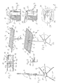
- the tumble dryer comprises a vertical stand 2 anchored in a lower stand 1, which carries at its upper end a collapsible, flat dryer frame 3.
- This has an elongated central support arm 4, which is attached to the top of a bracket 5, on the underside of which the upper end of the stand 2 is pivotally mounted.
- the support arm 4 can be pivoted together with the bracket 5 in a position substantially perpendicular to the stand 2 and fixed in this position on the stand 2.
- the dryer frame 3 also has two lateral snap frames 6 and 7, which are arranged on both sides of the support arm 4 and each contain a clothes line 8, 9. Each snap frame 6, 7 is folded towards the support arm 4 and opened apart from the support arm 4.
- both folding frames 6 and 7 of the dryer frame 3 are folded towards the support arm 4 and the folded dryer frame 3 is pivoted into a position parallel to the stand 3, in which the bracket 5 is fixed to the stand 2.
- both snap frames 6 and 7 of the dryer frame 3 are unfolded away from the support arm 4 and the unfolded flat dryer frame 3 is pivoted into its horizontal position perpendicular to the stand 3, in which the bracket 5 is fixed to the stand 2.
- the flat dryer frame 3, as in Fig. 2 is fixed in its horizontal position on the stand 2.
- the snap frame 6 is folded towards the support arm 4, while the snap frame 7 is unfolded and projects laterally away from the support arm 4.
- Each snap frame 6 and 7 contains two cross members 10, each of which is pivotally connected to the support arm 4 and supports the clothesline 8 and 9, and a longitudinal member 11 connecting the two cross members 10 to each other and pivotally connected to them, which is arranged parallel to the support arm 4 is.
- a bearing body 12 is provided which is connected to the support arm 4 in a form-fitting manner and carries a pivot axis for the respective cross member 10. (Fig. 4) For the sake of clarity, this is preferably not shown in Fig. 4, formed by a metal pin fixed in the bearing body 12 pivot axis.
- a bearing body 12 which carries two mutually adjacent pivot axes, on each of which a cross member 10 of one of the two snap frames 6, 7 is pivotally mounted.
- Each bearing body 12 has a fastening section 13, with which it is positively pressed into an end face of the support arm 4, and two mutually opposite flanges 14, 15, in which two mutually parallel pivot axes for the cross members 10 of the two snap frames 6, 7 each in one Bearing eye 16, 17 are included.
- Each bearing body 13 is divided transversely to these pivot axes into an upper body 12a and a lower body 12b.
- the upper body 12a comprises the upper part 13a of the fastening section 13 of the bearing body 12 and its upper flange 14, in the bearing eyes 16 of which the two pivot axes are mounted above the top of the respective cross member 10.
- the lower body 12b comprises the lower part 13b of the fastening section 13 of the bearing body 12 and its lower flange 15, in the bearing eyes 17 of which the two pivot axes are mounted below the underside of the respective cross member 10.
- the fastening sections 13a, 13b of the upper body 12a and lower body 12b are positively connected to one another by a dowel pin 18 parallel to the two pivot axes.
- a bearing body 12 is preferred in which the upper body 12a and lower body 12b are each formed as plastic molded bodies, the two fastening sections 13a, 13b of the two plastic molded bodies are adapted to the cross section of the support arm 4 and the two flanges 14, 15 are arranged adjacent to the top and bottom of the crossmember 10 above and below the end section of the respective crossmember 10.
- the two plastic moldings are connected to one another in the area of their flanges 14, 15 by the two swivel axes each formed from a metal pin, and on the other hand in the area of their fastening sections 13a, 13b by the metal pins pressed into both fastening sections and parallel to the swivel axes Dowel pin 18 positively connected.
- each snap frame 6, 7, the tracks of the respective clothesline 8, 9 extend parallel to the side member 11 from one cross member 10 to the other.
- a support bar 20 which runs in the longitudinal direction of the crossmember 10 and is provided with through openings 19 for the clothesline 8, 9 and which is arranged in a conical, i.e. on its longitudinal edges undercut longitudinal groove 21 of the respective cross member 10 is slidably received.
- the base 1 lies with its underside on the floor of the respective installation site and has laterally projecting support struts 22 which are pivotably mounted in the base 1.
- the lower end section 2a of the stand 2 can be anchored in the base 1.
- a vertical receiving sleeve 23 is provided in the base 1, into which the end section 2a can be inserted.
- a clamping lever 24 is pivotally mounted in the base 1 to the side of the receiving sleeve 23, which has a clamping edge 25 facing the receiving sleeve 23, which describes a path when the clamping lever 24 is pivoted, which travels above the receiving sleeve 23 via its interior protrudes inside.
- the clamping lever 24 bridges the upper mouth of the receiving sleeve 23 by means of a passage opening 27 for the end section 2a of the stand 2 and ends in a laterally protruding handle 28 to be actuated with the foot.
- the clamping edge 25 of the clamping lever 24 facing the end section 2a is formed on the lower edge of the passage opening 27.
- the clamping lever 24 is biased upwards into its rest position (FIG. 7) by at least one spring 29, in which its clamping edge 25 protrudes inwards beyond the receiving sleeve 23 and blocks the receiving sleeve 23.
- clamping lever 24 If the clamping lever 24 is pressed down on its handle 28 against the spring 29, it is pivoted into its release position, in which its clamping edge 25 releases the interior of the receiving sleeve 23 and the end section 2a can be pushed into the receiving sleeve 23 unhindered. If the end section 2a is inserted into the receiving sleeve 23 and the clamping lever 24 is released, it is pivoted by the force of the spring 29 from the release position into the working position (FIG. 6), in which its clamping edge 25 on the outside of the lower end section 2a of the stand 2 abuts and clamps it in the receiving sleeve 23.
Landscapes
- Engineering & Computer Science (AREA)
- Textile Engineering (AREA)
- Detail Structures Of Washing Machines And Dryers (AREA)
- Holders For Apparel And Elements Relating To Apparel (AREA)
Applications Claiming Priority (3)
| Application Number | Priority Date | Filing Date | Title |
|---|---|---|---|
| AT83196A AT410557B (de) | 1996-05-10 | 1996-05-10 | Wäschetrockner |
| AT83196 | 1996-05-10 | ||
| AT831/96 | 1996-05-10 |
Publications (3)
| Publication Number | Publication Date |
|---|---|
| EP0806517A2 true EP0806517A2 (fr) | 1997-11-12 |
| EP0806517A3 EP0806517A3 (fr) | 1998-05-20 |
| EP0806517B1 EP0806517B1 (fr) | 2002-09-04 |
Family
ID=3500790
Family Applications (1)
| Application Number | Title | Priority Date | Filing Date |
|---|---|---|---|
| EP19970890083 Expired - Lifetime EP0806517B1 (fr) | 1996-05-10 | 1997-05-05 | Séchoir à linge |
Country Status (3)
| Country | Link |
|---|---|
| EP (1) | EP0806517B1 (fr) |
| AT (1) | AT410557B (fr) |
| DE (1) | DE59708102D1 (fr) |
Cited By (3)
| Publication number | Priority date | Publication date | Assignee | Title |
|---|---|---|---|---|
| EP0987361A1 (fr) * | 1998-08-28 | 2000-03-22 | Heinrich Wüster | Séchoir à linge pliant |
| RU2177520C1 (ru) * | 2000-08-17 | 2001-12-27 | Гусов Вячеслав Александрович | Сушилка бельевая наружная |
| US6951064B2 (en) | 2002-08-23 | 2005-10-04 | Wuester Heinrich | Clothes drier |
Family Cites Families (6)
| Publication number | Priority date | Publication date | Assignee | Title |
|---|---|---|---|---|
| NL270498A (fr) * | 1960-10-22 | |||
| AT228154B (fr) * | 1960-10-22 | 1963-07-10 | Patent Und Verwaltungs-Ag. | |
| GB1006026A (en) * | 1962-03-05 | 1965-09-29 | Hills Hoists Ltd | Improvements in and relating to clothes hoists |
| DE2628980A1 (de) * | 1976-06-28 | 1978-01-05 | Bernauer Erich Oswald | Mittelstandrohr-waeschetrockner mit scherenfoermig ausschwenkbaren fuessen |
| CH626128A5 (en) * | 1978-01-19 | 1981-10-30 | Sternet Ag | Clothes stand |
| US5090578A (en) * | 1990-09-24 | 1992-02-25 | Arnold Thomas N | Portable clothes line device |
-
1996
- 1996-05-10 AT AT83196A patent/AT410557B/de not_active IP Right Cessation
-
1997
- 1997-05-05 DE DE59708102T patent/DE59708102D1/de not_active Expired - Lifetime
- 1997-05-05 EP EP19970890083 patent/EP0806517B1/fr not_active Expired - Lifetime
Cited By (3)
| Publication number | Priority date | Publication date | Assignee | Title |
|---|---|---|---|---|
| EP0987361A1 (fr) * | 1998-08-28 | 2000-03-22 | Heinrich Wüster | Séchoir à linge pliant |
| RU2177520C1 (ru) * | 2000-08-17 | 2001-12-27 | Гусов Вячеслав Александрович | Сушилка бельевая наружная |
| US6951064B2 (en) | 2002-08-23 | 2005-10-04 | Wuester Heinrich | Clothes drier |
Also Published As
| Publication number | Publication date |
|---|---|
| EP0806517A3 (fr) | 1998-05-20 |
| DE59708102D1 (de) | 2002-10-10 |
| AT410557B (de) | 2003-06-25 |
| ATA83196A (de) | 2002-10-15 |
| EP0806517B1 (fr) | 2002-09-04 |
Similar Documents
| Publication | Publication Date | Title |
|---|---|---|
| DE2107477A1 (de) | Aufrollbare Markise | |
| DE69310292T2 (de) | Zusammenklappbarer Tisch | |
| EP0609476A1 (fr) | Séchoir répliable | |
| DE3750588T2 (de) | Scharnier für einen zusammenklappbaren Wäscheständer. | |
| EP0457034B1 (fr) | Séchoir à linge pliant | |
| EP0806517A2 (fr) | Séchoir à linge | |
| DE2553834A1 (de) | Vorrichtung zum transportieren und lagern und gegebenenfalls verpacken von konfektionierten gardinen oder vorhaengen | |
| WO1985001865A1 (fr) | Console en charpente a longueur d'encorbellement modifiable | |
| DE19906536A1 (de) | Wäschetrockner | |
| EP0485439B1 (fr) | Chariot a ustensiles | |
| DE4033977C2 (de) | Spannvorrichtung für Kettfäden | |
| EP0213280B1 (fr) | Séchoir à linge extensible | |
| EP0987361B1 (fr) | Séchoir à linge pliant | |
| DE2430083A1 (de) | Scheren-waeschetrockner | |
| DE2741836C2 (de) | Reinigungswagen | |
| DE1957772A1 (de) | Waeschetrockner | |
| EP1020373B1 (fr) | Cadre tubulaire pour récipient à ouverture supérieure | |
| AT516528B1 (de) | Teileinheit einer faserbahnmaschine und stuhlungsteil für die teileinheit einer faserbahnmaschine | |
| DE69531932T2 (de) | Vorrichtung zur Schaustellung | |
| DE3611110C2 (fr) | ||
| DE4037742A1 (de) | Vorrichtung zum aufhaengen von waeschestuecken, insbesondere zum trocknen derselben | |
| DE102015120336A1 (de) | Trocken- oder Wäscheständer | |
| DE60200430T2 (de) | Verbesserungen für zusammenklappbare Wandwäschetrockner | |
| DE534589C (de) | Staenderbadewanne | |
| CH518398A (de) | Wäschetrockner |
Legal Events
| Date | Code | Title | Description |
|---|---|---|---|
| PUAI | Public reference made under article 153(3) epc to a published international application that has entered the european phase |
Free format text: ORIGINAL CODE: 0009012 |
|
| AK | Designated contracting states |
Kind code of ref document: A2 Designated state(s): CH DE FR GB LI NL |
|
| PUAL | Search report despatched |
Free format text: ORIGINAL CODE: 0009013 |
|
| AK | Designated contracting states |
Kind code of ref document: A3 Designated state(s): CH DE FR GB LI NL |
|
| 17P | Request for examination filed |
Effective date: 19981028 |
|
| 17Q | First examination report despatched |
Effective date: 20010213 |
|
| GRAG | Despatch of communication of intention to grant |
Free format text: ORIGINAL CODE: EPIDOS AGRA |
|
| GRAG | Despatch of communication of intention to grant |
Free format text: ORIGINAL CODE: EPIDOS AGRA |
|
| GRAH | Despatch of communication of intention to grant a patent |
Free format text: ORIGINAL CODE: EPIDOS IGRA |
|
| GRAH | Despatch of communication of intention to grant a patent |
Free format text: ORIGINAL CODE: EPIDOS IGRA |
|
| GRAA | (expected) grant |
Free format text: ORIGINAL CODE: 0009210 |
|
| AK | Designated contracting states |
Kind code of ref document: B1 Designated state(s): CH DE FR GB LI NL |
|
| REG | Reference to a national code |
Ref country code: GB Ref legal event code: FG4D Free format text: NOT ENGLISH |
|
| REG | Reference to a national code |
Ref country code: CH Ref legal event code: EP |
|
| REF | Corresponds to: |
Ref document number: 59708102 Country of ref document: DE Date of ref document: 20021010 |
|
| REG | Reference to a national code |
Ref country code: CH Ref legal event code: NV Representative=s name: RITSCHER & PARTNER AG PATENTANWAELTE |
|
| GBT | Gb: translation of ep patent filed (gb section 77(6)(a)/1977) |
Effective date: 20021223 |
|
| ET | Fr: translation filed | ||
| PLBE | No opposition filed within time limit |
Free format text: ORIGINAL CODE: 0009261 |
|
| STAA | Information on the status of an ep patent application or granted ep patent |
Free format text: STATUS: NO OPPOSITION FILED WITHIN TIME LIMIT |
|
| 26N | No opposition filed |
Effective date: 20030605 |
|
| REG | Reference to a national code |
Ref country code: CH Ref legal event code: PCAR Free format text: RITSCHER & PARTNER AG;RESIRAIN 1;8125 ZOLLIKERBERG (CH) |
|
| PGFP | Annual fee paid to national office [announced via postgrant information from national office to epo] |
Ref country code: NL Payment date: 20080529 Year of fee payment: 12 |
|
| NLV4 | Nl: lapsed or anulled due to non-payment of the annual fee |
Effective date: 20091201 |
|
| PG25 | Lapsed in a contracting state [announced via postgrant information from national office to epo] |
Ref country code: NL Free format text: LAPSE BECAUSE OF NON-PAYMENT OF DUE FEES Effective date: 20091201 |
|
| PGFP | Annual fee paid to national office [announced via postgrant information from national office to epo] |
Ref country code: GB Payment date: 20110503 Year of fee payment: 15 |
|
| GBPC | Gb: european patent ceased through non-payment of renewal fee |
Effective date: 20120505 |
|
| PG25 | Lapsed in a contracting state [announced via postgrant information from national office to epo] |
Ref country code: GB Free format text: LAPSE BECAUSE OF NON-PAYMENT OF DUE FEES Effective date: 20120505 |
|
| REG | Reference to a national code |
Ref country code: CH Ref legal event code: PFA Owner name: WUESTER, HEINRICH, AT Free format text: FORMER OWNER: WUESTER, HEINRICH, AT |
|
| REG | Reference to a national code |
Ref country code: FR Ref legal event code: PLFP Year of fee payment: 20 |
|
| PGFP | Annual fee paid to national office [announced via postgrant information from national office to epo] |
Ref country code: CH Payment date: 20160531 Year of fee payment: 20 Ref country code: DE Payment date: 20160530 Year of fee payment: 20 |
|
| PGFP | Annual fee paid to national office [announced via postgrant information from national office to epo] |
Ref country code: FR Payment date: 20160520 Year of fee payment: 20 |
|
| REG | Reference to a national code |
Ref country code: DE Ref legal event code: R071 Ref document number: 59708102 Country of ref document: DE |
|
| REG | Reference to a national code |
Ref country code: CH Ref legal event code: PL |