EP0806503A1 - Maschine zum Falschdrallzwirnen eines Zwirns - Google Patents
Maschine zum Falschdrallzwirnen eines Zwirns Download PDFInfo
- Publication number
- EP0806503A1 EP0806503A1 EP97105860A EP97105860A EP0806503A1 EP 0806503 A1 EP0806503 A1 EP 0806503A1 EP 97105860 A EP97105860 A EP 97105860A EP 97105860 A EP97105860 A EP 97105860A EP 0806503 A1 EP0806503 A1 EP 0806503A1
- Authority
- EP
- European Patent Office
- Prior art keywords
- yarn
- untwisting tension
- doubled
- yarns
- tension
- Prior art date
- Legal status (The legal status is an assumption and is not a legal conclusion. Google has not performed a legal analysis and makes no representation as to the accuracy of the status listed.)
- Granted
Links
Images


Classifications
-
- D—TEXTILES; PAPER
- D02—YARNS; MECHANICAL FINISHING OF YARNS OR ROPES; WARPING OR BEAMING
- D02G—CRIMPING OR CURLING FIBRES, FILAMENTS, THREADS, OR YARNS; YARNS OR THREADS
- D02G1/00—Producing crimped or curled fibres, filaments, yarns, or threads, giving them latent characteristics
- D02G1/02—Producing crimped or curled fibres, filaments, yarns, or threads, giving them latent characteristics by twisting, fixing the twist and backtwisting, i.e. by imparting false twist
- D02G1/04—Devices for imparting false twist
-
- B—PERFORMING OPERATIONS; TRANSPORTING
- B65—CONVEYING; PACKING; STORING; HANDLING THIN OR FILAMENTARY MATERIAL
- B65H—HANDLING THIN OR FILAMENTARY MATERIAL, e.g. SHEETS, WEBS, CABLES
- B65H54/00—Winding, coiling, or depositing filamentary material
- B65H54/02—Winding and traversing material on to reels, bobbins, tubes, or like package cores or formers
- B65H54/026—Doubling winders, i.e. for winding two or more parallel yarns on a bobbin, e.g. in preparation for twisting or weaving
-
- B—PERFORMING OPERATIONS; TRANSPORTING
- B65—CONVEYING; PACKING; STORING; HANDLING THIN OR FILAMENTARY MATERIAL
- B65H—HANDLING THIN OR FILAMENTARY MATERIAL, e.g. SHEETS, WEBS, CABLES
- B65H63/00—Warning or safety devices, e.g. automatic fault detectors, stop-motions ; Quality control of the package
- B65H63/02—Warning or safety devices, e.g. automatic fault detectors, stop-motions ; Quality control of the package responsive to reduction in material tension, failure of supply, or breakage, of material
-
- D—TEXTILES; PAPER
- D01—NATURAL OR MAN-MADE THREADS OR FIBRES; SPINNING
- D01H—SPINNING OR TWISTING
- D01H1/00—Spinning or twisting machines in which the product is wound-up continuously
- D01H1/11—Spinning by false-twisting
-
- D—TEXTILES; PAPER
- D01—NATURAL OR MAN-MADE THREADS OR FIBRES; SPINNING
- D01H—SPINNING OR TWISTING
- D01H13/00—Other common constructional features, details or accessories
- D01H13/14—Warning or safety devices, e.g. automatic fault detectors, stop motions ; Monitoring the entanglement of slivers in drafting arrangements
- D01H13/16—Warning or safety devices, e.g. automatic fault detectors, stop motions ; Monitoring the entanglement of slivers in drafting arrangements responsive to reduction in material tension, failure of supply, or breakage, of material
-
- D—TEXTILES; PAPER
- D02—YARNS; MECHANICAL FINISHING OF YARNS OR ROPES; WARPING OR BEAMING
- D02G—CRIMPING OR CURLING FIBRES, FILAMENTS, THREADS, OR YARNS; YARNS OR THREADS
- D02G1/00—Producing crimped or curled fibres, filaments, yarns, or threads, giving them latent characteristics
- D02G1/02—Producing crimped or curled fibres, filaments, yarns, or threads, giving them latent characteristics by twisting, fixing the twist and backtwisting, i.e. by imparting false twist
- D02G1/0206—Producing crimped or curled fibres, filaments, yarns, or threads, giving them latent characteristics by twisting, fixing the twist and backtwisting, i.e. by imparting false twist by false-twisting
- D02G1/0266—Producing crimped or curled fibres, filaments, yarns, or threads, giving them latent characteristics by twisting, fixing the twist and backtwisting, i.e. by imparting false twist by false-twisting false-twisting machines
-
- B—PERFORMING OPERATIONS; TRANSPORTING
- B65—CONVEYING; PACKING; STORING; HANDLING THIN OR FILAMENTARY MATERIAL
- B65H—HANDLING THIN OR FILAMENTARY MATERIAL, e.g. SHEETS, WEBS, CABLES
- B65H2701/00—Handled material; Storage means
- B65H2701/30—Handled filamentary material
- B65H2701/31—Textiles threads or artificial strands of filaments
Definitions
- the present invention relates to a doubled yarn false twisting machine producing false twist processed yarn of a conjugated yarn provided with a control device for cutting all the yarns of the doubled yarn when one yarn of among a plurality of yarns that are doubled breaks.
- a mechanical yarn breakage detection device is also arranged upstream of the first feed rollers that are upstream of where the yarns are combined and does not influence the transfer of the false twist. A breakage in any single yarn may thus be detected before the yarns are combined.
- FIG. 6 A schematic drawing of a conventional device is shown in Figure 6 with the mechanical yarn breakage detection device 4 being arranged between the cutter 2 and first feed roller F1.
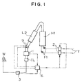
- the supplied yarn Y is passed by the first feed roller F1 via the cutter 2 and mechanical yarn breakage detection device 4, then passed through the primary heater H1 and the cooling plate L2, then false twist processed by the false twister 9, then had the untwisting tension detected by the untwisting tension detection device 1 and doubled by the entangling device IL, the conjugated yarn which has been doubled is wound by the winding device W via the yarn breakage detection device 3.
- a mechanical type and electrical capacitance type of yarn breakage detection devices are used on conventional false twisting machines and an anti static agent is used on partially draw textured yarn being the supply yarn. Detection of the presence or absence of yarn by the electrical capacitance yarn breakage detection device which detects whether there is a yarn by the capacitance of static electricity is very difficult as the yarn is almost completely uncharged and thus a mechanical yarn breakage detection device is used which detects the presence or absence of yarn by contact. This antistatic agent soon becomes ineffective if heated and thus a non-contact gentle electrical capacitance yarn breakage detection device is used for the yarn which has passed through the primary heater.
- the yarn end of the downstream side of the broken yarn may be wound on the winding package or the upstream side yarn end is not wound and becomes entangled on the rotating part of the shaft etc. of the feed roller. If this entanglement occurs, the yarn continues to be fed and forms a lump but even in this case, it is not detected by the yarn breakage detection device. In the worst possible case, this may cause the stoppage of the machine and thus require an operation to remove the entangled lump. As a result, it is preferable to arrange the yarn breakage detection device as far as possible downstream being the winding device side.
- an electical capacitance or mechanical yarn breakage detection device is not suitable for the detection of a yarn breakage after the doubling of the yarn.
- a high performance device that is able to detect a single yarn breakage whilst in the doubled yarn state has been proposed as an electrical capacitance yarn breakage detection device but this is unusable due to the high costs.
- a first aspect of the present invention detects that one yarn has broken based on a drop in untwisting tension above a fixed level by a tension detection device that detects the untwisting tension.
- the tension detection device for detecting the untwisting tension is also connected to the control device that operates the cutter upon judging a yarn breakage from a tension change.
- the control device that operates the cutter upon judging a yarn breakage from a tension change.
- the aforementioned tension detection device measures the combining force of the untwisting tension of the plurality of yarns which are doubled, defines the operating range and judges a yarn breakage when the untwisting tension drops outside of that range.
- the untwisting tension of the conjugated yarn is the sum of the untwisting tensions of each yarn comprising the conjugated yarn
- the tension changes by amount of the untwisting tension of that broken yarn.
- the untwisting tension is normally always changing to some degree, the change when a single yarn of the yarns comprising the conjugated yarn breaks may not necessarily be due to the untwisting tension of a broken yarn.
- an operating range is defined and the cutter is operated regardless of the presence or absence of yarn when the untwisting tension drops out of that range.
- gearing with the cutter that cuts all of the doubled yarns is comprised to be freely engageable.
- single yarn processing may be performed on the machine of a doubled yarn false twisting machine with the gearing between the tension detection device and cutter disengaged.
- Figure 1 is a schematic drawing of the doubled yarn false twisting machine of the present invention.
- Figure 2 is a side view of the doubled yarn false twisting machine of the present invention.
- Figure 3 is a schematic drawing of the untwisting tension detection device and false twisting machine used in one embodiment of the present invention.
- Figure 4 is a schematic drawing of the untwisting tension detection device and false twisting machine used in a second embodiment of the present invention.
- Figure 5 is a graph showing the relationship between the untwisting tension and yarn breakage.
- Figure 6 is a schematic drawing of a conventional doubled yarn false twisting machine.
- a draw texturizing machine M being a typical example of the present invention carries out texture processing of a synthetic filament yarn which is a melt-spun yarn and is shown in Figure 2 being a side view of a first embodiment of that.
- Ps is a supply package that is supported by a creel stand S.
- L1 is a guide pipe that guides a filament yarn Y unwound from the supply package Ps to a first feed roller F1.
- H1 is a primary heater that heat processes the yarn Y false twisted by a false twister 9.
- L2 is a cooling plate that fixes the properties of the yarn heat processed by the primary heater H1 by cooling.
- IL is the entangling device which entangles the yarn Y comprising a plurality of fiber bundles in approximately uniform intervals by a fluid and is able to form conjugated yarn by entangling a plurality of single yarns. Furthermore, when the entangling process is carried out, the unwinding properties are improved in the case of conjugated yarn or single yarn.
- O is an oiling roller that applies a lubricant to the yarn Y.
- W is a winding device that winds the yarn Y on a package Pw.
- the draw texturizing machine M is arranged with the creel stand S along the frame K and the filament yarn Y of the supply packages Ps supported on this creel stand S is unwound and guided to the first feed roller F1 by the guide pipe L1.
- a cutter 2 is arranged at the yarn exit hole of this guide pipe L1.
- the filament yarn Y is false twisted and heat fixed while being draw textured and bulkiness process is imparted on the filament yarn Y.
- the entangling device IL it is wound on the package Pw by the winding device W via the third feed roller F3, fourth feed roller F4, yarn breakage detection device 3, operation alley L3 and oiling roller O.
- 3 is the yarn breakage detection device which operates the cutter 2 and cuts the yarn Y upon detecting a yarn breakage.
- 1 is the untwisting tension detection device which also serves as a yarn breakage detection device and which sends signals to a control part 6 by obtaining various information necessary for quality management of the package such as changes in untwisting tension T by an internal sensor 5 and controls the untwisting tension T of the yarn Y by a contact pressure control means such as a cylinder or the like (not shown in the drawing) that adjusts the contact pressure of the false twister 9, based on the suitable signals sent from the control part 6.
- a yarn breakage is set for when the untwisting tension T shows a change exceeding the management range and the cutter 2 is operated by a signal from the control part 6.
- the yarn Y via the cutter 2 passes the first feed roller F1, primary heater H1, cooling plate L2, is false twist processed by the false twister 9, has the untwisting tension T detected by the untwisting tension detection device 1 and that result is entered in the control part 6.
- the control part 6 is pre-entered with target values for the untwisting tension T, the tension upper limit Tu and lower limit Td being the control range with respect to that target value To are entered simultaneously and the untwisting tension T of the false twister 9 is controlled via the contact pressure control means so as to be the target value To based on the untwisting tension T from the sensor 5.
- high quality yarn Y which had been controlled such that the untwisting tension T was within the target range is wound as a doubled conjugated yarn by the winding device W via the yarn breakage detection device 3 after being doubled by the entangling device IL.
- a first embodiment of the present invention has an untwisting tension detection device 1 with a plurality of internal sensors 5 and such an arrangement is shown in Figure 3 with two internal sensors 5.
- the conjugated yarn comprises two doubled yarns, the yarn path is seperate for each yarn Y so that the untwisting tension T may be detected and two each of a moving guide roller 8 and sensor 5 are arranged.
- Supposing the untwisting tension T of the conjugated yarn is for example 100g, with the untwisting tension of one yarn at 70g and the untwisting tension of the other at 30g. If a conjugated yarn of higher quality is to be produced, an embodiment arranged with such a plurality of sensors in the untwisting tension detection device 1 is able to produce better yarn by controlling the untwisting tensions of each of the composing yarns.
- the untwisting tension detection device 1 has a yarn path made of a guide 7 of which the shaft is fixed and a guide 8 that is linked to the sensor 5 and moves in response to the yarn tension, and measures the untwisting tension of the yarn Y passing along this yarn path.
- a single yarn false twisted by the false twister 9 passes along one yarn path.
- supposing a conjugated yarn YC is comprised of two single yarns being a 150 denier yarn YA and 75 denier yarn YB
- a yarn breakage when the untwisting tension T of the yarn YA is 70g and the untwisting tension T of the yarn YB is 30g. If a yarn breakage occurred in yarn YB, the untwisting tension T of the sensor 5 detecting the untwisting tension T of YB would become a value close to zero, a yarn breakage would be recognised and, the cutter 2 would be operated and the yarns YA, YB would be cut.
- one sensor 5 only detects the untwisting tension T of a single yarn Y but when the winding tension has become 0, it should be thought of as a yarn breakage but without actual experimentation, this can not be known. There is a margin of error and the untwisting tension T rarely reaches 0 even if a yarn breakage has occurred. Therefore, it is preferable to judge a yarn breakage when the untwisting tension T is close to 0 by reference to the margin of error and degree of change of the untwisting tension T.
- a yarn breakage may also be judged by large changes in the unwinding tension T of a single yarn such as changes of over half the unwinding tension T.
- a first embodiment of the present invention described a conjugate yarn comprising two yarns but naturally the number of yarns comprising the conjugate yarn is not necessarily limited to two.
- the cutter 2 operated by a single untwisting tension detection device 1 may be freely set corresponding to the number of yarns comprising the conjugated yarn.
- the sensors 5 inside the single untwisting tension detection device 1 are not limited to two and are preferably the same number as the number of yarns comprising the conjugated yarn.
- the untwisting tension T decreases as the yarn delivery speed becomes slower relative to the contact pressure of the belt.
- the contact pressure of the contact pressure control means decreases, the slippage between the yarn and belts increases, the delivery amount is reduced and the untwisting tension T rises.
- the vertical axis is the unwinding tension T and the horizontal axis is the time.
- the control of the contact pressure of the belts is carried out by control of the contact pressure control means by signals from the control part 6. If the value of the untwisting tension T detected by the untwisting tension detection device 1 and sent to the control part 6 increases and exceeds the upper limit Tu, a signal is sent to the contact pressure control means from the control part 6, the contact pressure between the false twister 9 and the yarn Y is increased and the contact pressure of the belts rises. Accordingly, the increased untwisting tension T starts to fall and falls below the upper limit Tu.
- a signal is continuously sent to the contact pressure control means from the the control part 6 targeting the target value To, the contact pressure increases and the untwisting tension T decreases.
- the contact pressure of the contact pressure control means is lowered and the belt contact pressure drops. Accordingly, the lowered untwisting tension T starts to rise and rises above the lower limit Td. The contact pressure of the belts is further lowered thus increasing the untwisting tension T thus targeting the target value To.
- Controlling the untwisting tension T to the target value To is carried out by the repetition of the control of this contact pressure control means.
- the untwisting tension T of the entire conjugated yarn is the sum of the single yarns comprising the conjugated yarn
- the untwisting tension becomes the sum minus the broken yarn.
- the target value To, upper limit Tu, lower limit Td and operating lower limit Tmin are determined by the entire conjugated yarn. If a single yarn breaks, the value of the untwisting tension decreases only by the value of the untwisting tension of the broken yarn thus it is correct to judge a yarn breakage when the operating lower limit Tmin has been exceeded.
- supposing a conjugated yarn YC is comprised of two single yarns being a 150 denier yarn YA and 75 denier yarn YB, let us consider a yarn breakage of yarn YB and the wrapping of the yarn end around the shaft of the first feed rollers F1 when the untwisting tension of the yarn YA is 70g and the untwisting tension of the yarn YB is 30g.
- the untwisting tension T of the conjugated yarn YC is 100g being the sum of the untwisting tensions of each of yarns YA and YB. Accordingly, the target value To is 100g.
- the untwisting tension detection device 1 When the untwisting tension T is approximately 100g, the normal change would be ⁇ 3 to 5g, the untwisting tension T would be kept within the target range by controlling the false twister 9 so that the upper limit Tu would be 105g and the lower limit Td would be 95g if the change was 5g.
- the untwisting tension detection device 1 When a yarn breakage occurs, the untwisting tension detection device 1 would then register an untwisting tension value which has a change range at around 70g instead of 100g and the range should then be from 75g to 65g. Supposing the operating lower limit Tmin was set at 90g, a yarn breakage would be judged and the cutter 2 operated thus cutting yarns YA and YB as the untwisting tension had fallen below the operating lower limit Tmin.
- the thickness and untwisting tension T of the conjugated yarn is not limited to the numerical values described in the above embodiments and may correspond to a variety of conjugated yarns.
- the doubled yarn false twisting machine is not limited to that described in the above embodiments but any doubled yarn false twisting machine may be applied.
- the untwisting tension T determining cutting of the yarn may be freely set as the count and type of the yarn Y comprising the doubled yarn being produced are numerous and the cutter 2 to be operated may be freely chosen.
- the structure of an already existing doubled yarn false twisting machine may be utilised by the adjustment of the program controlling the untwisting tension and cutter and thus may be cheaper than currently operating false twisting machines.
- a conventional mechanical yarn breakage detection device arranged per every one yarn close to the first feed rollers may be abolished thus reducing the number of parts and labour during assembly and reducing production costs.
- a yarn breakage may be detected and the cutter operated even in the case of specifications where the untwisting tension of a plurality of yarns is measured in a single sensor of the untwisting tension detection device.
Landscapes
- Engineering & Computer Science (AREA)
- Textile Engineering (AREA)
- Mechanical Engineering (AREA)
- Quality & Reliability (AREA)
- Filamentary Materials, Packages, And Safety Devices Therefor (AREA)
- Yarns And Mechanical Finishing Of Yarns Or Ropes (AREA)
- Treatment Of Fiber Materials (AREA)
- Spinning Or Twisting Of Yarns (AREA)
- Constituent Portions Of Griding Lathes, Driving, Sensing And Control (AREA)
Applications Claiming Priority (3)
| Application Number | Priority Date | Filing Date | Title |
|---|---|---|---|
| JP11239696 | 1996-05-07 | ||
| JP112396/96 | 1996-05-07 | ||
| JP11239696A JP3079997B2 (ja) | 1996-05-07 | 1996-05-07 | 合糸仮撚機の糸切れ検出装置 |
Publications (2)
| Publication Number | Publication Date |
|---|---|
| EP0806503A1 true EP0806503A1 (de) | 1997-11-12 |
| EP0806503B1 EP0806503B1 (de) | 2002-10-02 |
Family
ID=14585620
Family Applications (1)
| Application Number | Title | Priority Date | Filing Date |
|---|---|---|---|
| EP19970105860 Expired - Lifetime EP0806503B1 (de) | 1996-05-07 | 1997-04-09 | Maschine zum Falschdrallzwirnen eines Zwirns |
Country Status (6)
| Country | Link |
|---|---|
| EP (1) | EP0806503B1 (de) |
| JP (1) | JP3079997B2 (de) |
| KR (1) | KR100456745B1 (de) |
| CN (1) | CN1057574C (de) |
| DE (1) | DE69715957T2 (de) |
| TW (1) | TW335420B (de) |
Cited By (6)
| Publication number | Priority date | Publication date | Assignee | Title |
|---|---|---|---|---|
| EP0864677A1 (de) * | 1997-03-14 | 1998-09-16 | Murata Kikai Kabushiki Kaisha | Fadenspannungsregelung für Texturiervorrichtung zum Falschdrallzwirnen eines Zwirns |
| EP1424411A1 (de) * | 2002-11-27 | 2004-06-02 | Polyfelt Gesellschaft m.b.H. | Vorrichtung zur Verbesserung der Spinnstabilität |
| US9422928B2 (en) | 2010-08-27 | 2016-08-23 | Koninklijke Philips N.V. | Electric motor thermal energy isolation |
| EP3540104A1 (de) * | 2018-03-16 | 2019-09-18 | TMT Machinery, Inc. | Strecktexturierungsmaschine |
| CN110592750A (zh) * | 2019-10-10 | 2019-12-20 | 海盐县梦芝舟毛纺厂 | 一种自调节并线机 |
| CN116685729A (zh) * | 2021-03-16 | 2023-09-01 | 日本Tmt机械株式会社 | 假捻加工机 |
Families Citing this family (1)
| Publication number | Priority date | Publication date | Assignee | Title |
|---|---|---|---|---|
| CN102517718A (zh) * | 2011-11-15 | 2012-06-27 | 海宁市建利纺织有限公司 | 毛感曲丝假捻机 |
Citations (3)
| Publication number | Priority date | Publication date | Assignee | Title |
|---|---|---|---|---|
| US4947633A (en) * | 1988-02-20 | 1990-08-14 | Hans Stahlecker | Process and an arrangement for producing packages to be used as feeding packages for twisting |
| EP0495446A1 (de) * | 1991-01-17 | 1992-07-22 | Barmag Ag | Verfahren und Vorrichtung zum Überwachen der Qualität eines falschdralltexturierten Garns |
| US5502961A (en) * | 1992-08-31 | 1996-04-02 | Murata Kikai Kabushiki Kaisha | False twister and method for controlling same |
Family Cites Families (3)
| Publication number | Priority date | Publication date | Assignee | Title |
|---|---|---|---|---|
| KR950009866B1 (ko) * | 1991-09-06 | 1995-08-29 | 후지레비오 가부시끼가이샤 | 4-히드록시테트라하이드로피란-2-온 유도체 및 그의 합성에 이용되는 중간체 |
| JPH07133535A (ja) * | 1993-11-08 | 1995-05-23 | Murata Mach Ltd | 延伸仮撚機の管理システム |
| JPH0892828A (ja) * | 1994-09-21 | 1996-04-09 | Unitika Ltd | 摩擦仮撚における異常部除去方法 |
-
1996
- 1996-05-07 JP JP11239696A patent/JP3079997B2/ja not_active Expired - Lifetime
- 1996-12-31 TW TW085116354A patent/TW335420B/zh not_active IP Right Cessation
-
1997
- 1997-03-06 KR KR1019970007360A patent/KR100456745B1/ko not_active Expired - Lifetime
- 1997-04-09 DE DE1997615957 patent/DE69715957T2/de not_active Expired - Lifetime
- 1997-04-09 EP EP19970105860 patent/EP0806503B1/de not_active Expired - Lifetime
- 1997-05-06 CN CN97104220A patent/CN1057574C/zh not_active Expired - Lifetime
Patent Citations (3)
| Publication number | Priority date | Publication date | Assignee | Title |
|---|---|---|---|---|
| US4947633A (en) * | 1988-02-20 | 1990-08-14 | Hans Stahlecker | Process and an arrangement for producing packages to be used as feeding packages for twisting |
| EP0495446A1 (de) * | 1991-01-17 | 1992-07-22 | Barmag Ag | Verfahren und Vorrichtung zum Überwachen der Qualität eines falschdralltexturierten Garns |
| US5502961A (en) * | 1992-08-31 | 1996-04-02 | Murata Kikai Kabushiki Kaisha | False twister and method for controlling same |
Cited By (6)
| Publication number | Priority date | Publication date | Assignee | Title |
|---|---|---|---|---|
| EP0864677A1 (de) * | 1997-03-14 | 1998-09-16 | Murata Kikai Kabushiki Kaisha | Fadenspannungsregelung für Texturiervorrichtung zum Falschdrallzwirnen eines Zwirns |
| EP1424411A1 (de) * | 2002-11-27 | 2004-06-02 | Polyfelt Gesellschaft m.b.H. | Vorrichtung zur Verbesserung der Spinnstabilität |
| US9422928B2 (en) | 2010-08-27 | 2016-08-23 | Koninklijke Philips N.V. | Electric motor thermal energy isolation |
| EP3540104A1 (de) * | 2018-03-16 | 2019-09-18 | TMT Machinery, Inc. | Strecktexturierungsmaschine |
| CN110592750A (zh) * | 2019-10-10 | 2019-12-20 | 海盐县梦芝舟毛纺厂 | 一种自调节并线机 |
| CN116685729A (zh) * | 2021-03-16 | 2023-09-01 | 日本Tmt机械株式会社 | 假捻加工机 |
Also Published As
| Publication number | Publication date |
|---|---|
| HK1003898A1 (en) | 1998-11-13 |
| EP0806503B1 (de) | 2002-10-02 |
| CN1057574C (zh) | 2000-10-18 |
| KR970075002A (ko) | 1997-12-10 |
| JP3079997B2 (ja) | 2000-08-21 |
| JPH09296331A (ja) | 1997-11-18 |
| DE69715957T2 (de) | 2003-08-07 |
| CN1165210A (zh) | 1997-11-19 |
| KR100456745B1 (ko) | 2005-02-23 |
| DE69715957D1 (de) | 2002-11-07 |
| TW335420B (en) | 1998-07-01 |
Similar Documents
| Publication | Publication Date | Title |
|---|---|---|
| US6536087B2 (en) | Method and apparatus for continuously unwinding and processing a yarn | |
| US6199361B1 (en) | False twist texturing machine | |
| US4356690A (en) | Fasciated yarn | |
| US5343601A (en) | Yarn spinning method with high-speed winding | |
| US5661880A (en) | Method and apparatus for producing a multifilament yarn by a spin-draw process | |
| CN1043688C (zh) | 监控运动中的纱线的方法 | |
| US7137238B2 (en) | Yarn quality assurance method and yarn processing machine | |
| EP0806503B1 (de) | Maschine zum Falschdrallzwirnen eines Zwirns | |
| JP2003253531A (ja) | 糸切れ防止装置及び同糸切れ防止手段を有する糸条加工機類 | |
| JP2003293236A (ja) | 繊維トウの繋ぎ部分検出センサー及び同センサーを用いた制御方法 | |
| US3341913A (en) | Drawing and bulking of synthetic polymer yarns | |
| US4012816A (en) | Method and apparatus for processing thermoplastic yarn | |
| US5036568A (en) | Method and system to detect the position and tension of yarn being air textured | |
| IE41990B1 (en) | A process for texturing thermoplastic synthetic yarns | |
| JP3509870B2 (ja) | 加工糸の生産 | |
| US20060201129A1 (en) | Continuous constant tension air covering | |
| US4343144A (en) | Control arrangement for a textile machine | |
| US4309801A (en) | Texturizing process | |
| JPH1060745A (ja) | 嵩高弾性糸の製造方法 | |
| US3938307A (en) | Drawing and texturing by false twist crimping of synthetic textile filament | |
| JPH11100735A (ja) | 延伸仮撚機 | |
| EP0907079A1 (de) | Vorrichtung zur Qualitätskontrolle eines texturiertem Filamentgarn | |
| US7454889B2 (en) | Method for producing an effect yarn on an open-end rotor spinning machine, and corresponding effect yarn | |
| CA1138631A (en) | Fasciated yarn and a process for making the same | |
| US5351471A (en) | Machine having a reduced height for twisting and texturing a yarn |
Legal Events
| Date | Code | Title | Description |
|---|---|---|---|
| PUAI | Public reference made under article 153(3) epc to a published international application that has entered the european phase |
Free format text: ORIGINAL CODE: 0009012 |
|
| AK | Designated contracting states |
Kind code of ref document: A1 Designated state(s): CH DE FR IT LI |
|
| 17P | Request for examination filed |
Effective date: 19980115 |
|
| 17Q | First examination report despatched |
Effective date: 20000518 |
|
| GRAG | Despatch of communication of intention to grant |
Free format text: ORIGINAL CODE: EPIDOS AGRA |
|
| GRAG | Despatch of communication of intention to grant |
Free format text: ORIGINAL CODE: EPIDOS AGRA |
|
| GRAH | Despatch of communication of intention to grant a patent |
Free format text: ORIGINAL CODE: EPIDOS IGRA |
|
| GRAH | Despatch of communication of intention to grant a patent |
Free format text: ORIGINAL CODE: EPIDOS IGRA |
|
| GRAA | (expected) grant |
Free format text: ORIGINAL CODE: 0009210 |
|
| AK | Designated contracting states |
Kind code of ref document: B1 Designated state(s): CH DE FR IT LI |
|
| REG | Reference to a national code |
Ref country code: CH Ref legal event code: EP |
|
| REF | Corresponds to: |
Ref document number: 69715957 Country of ref document: DE Date of ref document: 20021107 |
|
| REG | Reference to a national code |
Ref country code: CH Ref legal event code: NV Representative=s name: E. BLUM & CO. PATENTANWAELTE |
|
| ET | Fr: translation filed | ||
| PLBE | No opposition filed within time limit |
Free format text: ORIGINAL CODE: 0009261 |
|
| STAA | Information on the status of an ep patent application or granted ep patent |
Free format text: STATUS: NO OPPOSITION FILED WITHIN TIME LIMIT |
|
| 26N | No opposition filed |
Effective date: 20030703 |
|
| PGFP | Annual fee paid to national office [announced via postgrant information from national office to epo] |
Ref country code: FR Payment date: 20050419 Year of fee payment: 9 |
|
| PGFP | Annual fee paid to national office [announced via postgrant information from national office to epo] |
Ref country code: CH Payment date: 20050422 Year of fee payment: 9 |
|
| PG25 | Lapsed in a contracting state [announced via postgrant information from national office to epo] |
Ref country code: LI Free format text: LAPSE BECAUSE OF NON-PAYMENT OF DUE FEES Effective date: 20060430 Ref country code: CH Free format text: LAPSE BECAUSE OF NON-PAYMENT OF DUE FEES Effective date: 20060430 |
|
| PGFP | Annual fee paid to national office [announced via postgrant information from national office to epo] |
Ref country code: IT Payment date: 20060430 Year of fee payment: 10 |
|
| REG | Reference to a national code |
Ref country code: CH Ref legal event code: PL |
|
| REG | Reference to a national code |
Ref country code: FR Ref legal event code: ST Effective date: 20061230 |
|
| PG25 | Lapsed in a contracting state [announced via postgrant information from national office to epo] |
Ref country code: FR Free format text: LAPSE BECAUSE OF NON-PAYMENT OF DUE FEES Effective date: 20060502 |
|
| PG25 | Lapsed in a contracting state [announced via postgrant information from national office to epo] |
Ref country code: IT Free format text: LAPSE BECAUSE OF NON-PAYMENT OF DUE FEES Effective date: 20070409 |
|
| REG | Reference to a national code |
Ref country code: DE Ref legal event code: R082 Ref document number: 69715957 Country of ref document: DE Representative=s name: WEICKMANN & WEICKMANN PATENTANWAELTE - RECHTSA, DE Ref country code: DE Ref legal event code: R082 Ref document number: 69715957 Country of ref document: DE Representative=s name: PATENTANWAELTE WEICKMANN & WEICKMANN, DE |
|
| PGFP | Annual fee paid to national office [announced via postgrant information from national office to epo] |
Ref country code: DE Payment date: 20160421 Year of fee payment: 20 |
|
| REG | Reference to a national code |
Ref country code: DE Ref legal event code: R071 Ref document number: 69715957 Country of ref document: DE |