EP0806281A1 - Dispositif filtrant permettant la filtration homogène des matières plastiques fondues - Google Patents
Dispositif filtrant permettant la filtration homogène des matières plastiques fondues Download PDFInfo
- Publication number
- EP0806281A1 EP0806281A1 EP97107267A EP97107267A EP0806281A1 EP 0806281 A1 EP0806281 A1 EP 0806281A1 EP 97107267 A EP97107267 A EP 97107267A EP 97107267 A EP97107267 A EP 97107267A EP 0806281 A1 EP0806281 A1 EP 0806281A1
- Authority
- EP
- European Patent Office
- Prior art keywords
- filter
- filter device
- flow
- plastic melt
- gap width
- Prior art date
- Legal status (The legal status is an assumption and is not a legal conclusion. Google has not performed a legal analysis and makes no representation as to the accuracy of the status listed.)
- Granted
Links
- 239000004033 plastic Substances 0.000 title claims abstract description 43
- 229920003023 plastic Polymers 0.000 title claims abstract description 43
- 239000000155 melt Substances 0.000 title claims description 22
- 238000001914 filtration Methods 0.000 title claims description 5
- 230000007423 decrease Effects 0.000 claims abstract description 8
- 238000001228 spectrum Methods 0.000 description 8
- 238000009826 distribution Methods 0.000 description 5
- 230000015556 catabolic process Effects 0.000 description 3
- 239000002245 particle Substances 0.000 description 3
- 238000009827 uniform distribution Methods 0.000 description 3
- 238000006731 degradation reaction Methods 0.000 description 2
- 238000013461 design Methods 0.000 description 2
- 238000010586 diagram Methods 0.000 description 2
- 238000006073 displacement reaction Methods 0.000 description 2
- 238000011001 backwashing Methods 0.000 description 1
- 238000011161 development Methods 0.000 description 1
- 238000003780 insertion Methods 0.000 description 1
- 230000037431 insertion Effects 0.000 description 1
- 239000000463 material Substances 0.000 description 1
- 238000010327 methods by industry Methods 0.000 description 1
- 238000012856 packing Methods 0.000 description 1
- 229920000728 polyester Polymers 0.000 description 1
- -1 polyethylene terephthalate Polymers 0.000 description 1
- 229920000139 polyethylene terephthalate Polymers 0.000 description 1
- 239000005020 polyethylene terephthalate Substances 0.000 description 1
- 229920000642 polymer Polymers 0.000 description 1
Images


Classifications
-
- B—PERFORMING OPERATIONS; TRANSPORTING
- B01—PHYSICAL OR CHEMICAL PROCESSES OR APPARATUS IN GENERAL
- B01D—SEPARATION
- B01D29/00—Filters with filtering elements stationary during filtration, e.g. pressure or suction filters, not covered by groups B01D24/00 - B01D27/00; Filtering elements therefor
- B01D29/88—Filters with filtering elements stationary during filtration, e.g. pressure or suction filters, not covered by groups B01D24/00 - B01D27/00; Filtering elements therefor having feed or discharge devices
- B01D29/92—Filters with filtering elements stationary during filtration, e.g. pressure or suction filters, not covered by groups B01D24/00 - B01D27/00; Filtering elements therefor having feed or discharge devices for discharging filtrate
- B01D29/925—Filters with filtering elements stationary during filtration, e.g. pressure or suction filters, not covered by groups B01D24/00 - B01D27/00; Filtering elements therefor having feed or discharge devices for discharging filtrate containing liquid displacement elements or cores
-
- B—PERFORMING OPERATIONS; TRANSPORTING
- B01—PHYSICAL OR CHEMICAL PROCESSES OR APPARATUS IN GENERAL
- B01D—SEPARATION
- B01D29/00—Filters with filtering elements stationary during filtration, e.g. pressure or suction filters, not covered by groups B01D24/00 - B01D27/00; Filtering elements therefor
- B01D29/39—Filters with filtering elements stationary during filtration, e.g. pressure or suction filters, not covered by groups B01D24/00 - B01D27/00; Filtering elements therefor with hollow discs side by side on, or around, one or more tubes, e.g. of the leaf type
- B01D29/41—Filters with filtering elements stationary during filtration, e.g. pressure or suction filters, not covered by groups B01D24/00 - B01D27/00; Filtering elements therefor with hollow discs side by side on, or around, one or more tubes, e.g. of the leaf type mounted transversely on the tube
-
- B—PERFORMING OPERATIONS; TRANSPORTING
- B01—PHYSICAL OR CHEMICAL PROCESSES OR APPARATUS IN GENERAL
- B01D—SEPARATION
- B01D29/00—Filters with filtering elements stationary during filtration, e.g. pressure or suction filters, not covered by groups B01D24/00 - B01D27/00; Filtering elements therefor
- B01D29/88—Filters with filtering elements stationary during filtration, e.g. pressure or suction filters, not covered by groups B01D24/00 - B01D27/00; Filtering elements therefor having feed or discharge devices
- B01D29/90—Filters with filtering elements stationary during filtration, e.g. pressure or suction filters, not covered by groups B01D24/00 - B01D27/00; Filtering elements therefor having feed or discharge devices for feeding
- B01D29/902—Filters with filtering elements stationary during filtration, e.g. pressure or suction filters, not covered by groups B01D24/00 - B01D27/00; Filtering elements therefor having feed or discharge devices for feeding containing fixed liquid displacement elements or cores
-
- B—PERFORMING OPERATIONS; TRANSPORTING
- B29—WORKING OF PLASTICS; WORKING OF SUBSTANCES IN A PLASTIC STATE IN GENERAL
- B29C—SHAPING OR JOINING OF PLASTICS; SHAPING OF MATERIAL IN A PLASTIC STATE, NOT OTHERWISE PROVIDED FOR; AFTER-TREATMENT OF THE SHAPED PRODUCTS, e.g. REPAIRING
- B29C48/00—Extrusion moulding, i.e. expressing the moulding material through a die or nozzle which imparts the desired form; Apparatus therefor
- B29C48/25—Component parts, details or accessories; Auxiliary operations
- B29C48/254—Sealing means
- B29C48/2545—Sealing means for filters
-
- B—PERFORMING OPERATIONS; TRANSPORTING
- B29—WORKING OF PLASTICS; WORKING OF SUBSTANCES IN A PLASTIC STATE IN GENERAL
- B29C—SHAPING OR JOINING OF PLASTICS; SHAPING OF MATERIAL IN A PLASTIC STATE, NOT OTHERWISE PROVIDED FOR; AFTER-TREATMENT OF THE SHAPED PRODUCTS, e.g. REPAIRING
- B29C48/00—Extrusion moulding, i.e. expressing the moulding material through a die or nozzle which imparts the desired form; Apparatus therefor
- B29C48/25—Component parts, details or accessories; Auxiliary operations
- B29C48/36—Means for plasticising or homogenising the moulding material or forcing it through the nozzle or die
- B29C48/50—Details of extruders
- B29C48/69—Filters or screens for the moulding material
-
- B—PERFORMING OPERATIONS; TRANSPORTING
- B01—PHYSICAL OR CHEMICAL PROCESSES OR APPARATUS IN GENERAL
- B01D—SEPARATION
- B01D2201/00—Details relating to filtering apparatus
- B01D2201/44—Special measures allowing the even or uniform distribution of fluid along the length of a conduit
-
- B—PERFORMING OPERATIONS; TRANSPORTING
- B29—WORKING OF PLASTICS; WORKING OF SUBSTANCES IN A PLASTIC STATE IN GENERAL
- B29B—PREPARATION OR PRETREATMENT OF THE MATERIAL TO BE SHAPED; MAKING GRANULES OR PREFORMS; RECOVERY OF PLASTICS OR OTHER CONSTITUENTS OF WASTE MATERIAL CONTAINING PLASTICS
- B29B7/00—Mixing; Kneading
- B29B7/30—Mixing; Kneading continuous, with mechanical mixing or kneading devices
- B29B7/58—Component parts, details or accessories; Auxiliary operations
-
- B—PERFORMING OPERATIONS; TRANSPORTING
- B29—WORKING OF PLASTICS; WORKING OF SUBSTANCES IN A PLASTIC STATE IN GENERAL
- B29C—SHAPING OR JOINING OF PLASTICS; SHAPING OF MATERIAL IN A PLASTIC STATE, NOT OTHERWISE PROVIDED FOR; AFTER-TREATMENT OF THE SHAPED PRODUCTS, e.g. REPAIRING
- B29C48/00—Extrusion moulding, i.e. expressing the moulding material through a die or nozzle which imparts the desired form; Apparatus therefor
- B29C48/03—Extrusion moulding, i.e. expressing the moulding material through a die or nozzle which imparts the desired form; Apparatus therefor characterised by the shape of the extruded material at extrusion
-
- B—PERFORMING OPERATIONS; TRANSPORTING
- B29—WORKING OF PLASTICS; WORKING OF SUBSTANCES IN A PLASTIC STATE IN GENERAL
- B29C—SHAPING OR JOINING OF PLASTICS; SHAPING OF MATERIAL IN A PLASTIC STATE, NOT OTHERWISE PROVIDED FOR; AFTER-TREATMENT OF THE SHAPED PRODUCTS, e.g. REPAIRING
- B29C48/00—Extrusion moulding, i.e. expressing the moulding material through a die or nozzle which imparts the desired form; Apparatus therefor
- B29C48/25—Component parts, details or accessories; Auxiliary operations
- B29C48/27—Cleaning; Purging; Avoiding contamination
- B29C48/2725—Cleaning; Purging; Avoiding contamination of filters
- B29C48/273—Cleaning; Purging; Avoiding contamination of filters using back flow
-
- B—PERFORMING OPERATIONS; TRANSPORTING
- B29—WORKING OF PLASTICS; WORKING OF SUBSTANCES IN A PLASTIC STATE IN GENERAL
- B29C—SHAPING OR JOINING OF PLASTICS; SHAPING OF MATERIAL IN A PLASTIC STATE, NOT OTHERWISE PROVIDED FOR; AFTER-TREATMENT OF THE SHAPED PRODUCTS, e.g. REPAIRING
- B29C48/00—Extrusion moulding, i.e. expressing the moulding material through a die or nozzle which imparts the desired form; Apparatus therefor
- B29C48/25—Component parts, details or accessories; Auxiliary operations
- B29C48/36—Means for plasticising or homogenising the moulding material or forcing it through the nozzle or die
- B29C48/50—Details of extruders
- B29C48/69—Filters or screens for the moulding material
- B29C48/694—Cylindrical or conical filters
Definitions
- the invention relates to a filter device for uniformly filtering plastic melts, with a filter housing, in the interior of which parallel filter disks are arranged along a central filter rod, through which partial flows of the plastic melt to be filtered flow.
- Known filter devices generally have different geometries, such as a filter bowl geometry in which a single filter surface in the form of a cylinder forms the inner wall of the filter bowl, or consist of a filter cartridge arrangement in which a number of filter cartridges are accommodated in a filter housing, or consist of a cylindrical filter housing equipped with filter disks.
- a filter device for plastic melts in which candle filters are arranged in the filter housing along concentric circles, which consist of a support body and a filter material and through which the plastic melt to be filtered flows.
- Each candle filter in the support body contains a displacement body, which forms a gap of constant width with the inner wall of the support body.
- the packing density of the candle filter per unit volume decreases from the circumference to the center of the filter housing.
- flow bodies are arranged between the candle filters.
- DE-A-34 19 822 describes a filter device of a screw extruder for filtering the plastic melt emerging from the screw extruder, which has a filter housing with an inlet and outlet bore, with a displaceable therein transverse to the melt flow Change slide. At least one recess, which consists of an annular recess, in the interchangeable slide, serves to accommodate a sieve body. For the uniform distribution of the melt flow in the filter device and the compressive forces acting on the filter surface, the recess is annular and there is a melt channel connected to the inlet bore, in which the cylindrical sieve body envelops the insertion of the recess in a form-fitting manner.
- a flow bore running in the longitudinal axis of the interchangeable slide valve connects the inlet bore with the outlet bore in the filter housing.
- a displacer cone is built into the flow bore, creating an annular collecting channel which widens in the direction of flow of the melt towards the outlet bore.
- This filter device is a filter bowl which generally has a single filter surface in cylindrical form, which is arranged in the housing wall of the filter device.
- a uniform distribution of the melt flow in the filter and the pressure forces acting on the filter surface, as well as a full relief of the transverse forces acting on the guide surface of the interchangeable slide valve, is sought.
- the displacement cone in the melt channel is intended to reduce the flow resistance of the melt to a minimum in the interchangeable slide with flow-favorable cross-sectional conditions.
- the filter surface generally forms the largest part of the pot circumference or the housing wall, the outer shape of the filter bowl being similar to that of a cylindrical candle filter. If there are no or only very small dead zones in the filter device, then the residence time distribution is individual Particles narrow and the breakdown of the melt minimal. The residence time distribution describes the proportion of the mass particles of the plastic melt after which time has left the filter device.
- a prerequisite for keeping the dead times as short as possible is a complete flooding of the filter volume through the melt. This is most easily achieved by the fact that the speed vector within the filter bowl does not change, or changes only very little, both in terms of amount and direction. A design of a filter device in which, for example, the melt flow is deflected by 90 to 180 ° should therefore be avoided if possible.
- the object of the invention is to improve a filter device of the type described at the outset so that the throughput distribution of the melt over the individual filter disks is almost constant, the residence time is made uniform and shortened, the residence time spectrum is kept constant and narrow, the total pressure loss over the length the filter device is reduced and the melt degradation is kept very small.
- an inner diameter D of the interior of the filter housing tapers in the direction of flow of the plastic melt in accordance with a function greater than a second root function.
- the filter disks expediently have the same outer and inner diameters d ad and d id .
- the filter device according to the invention can be used, among other things, to filter low-viscosity plastic melts, for example made of polyethylene terephthalate (polyester), with throughputs of up to 5000 kg per hour, in particular from 50 to 600 kg per hour, with little pressure loss, short residence times and a very narrow residence time spectrum.
- a further advantage is a uniform filter disc allocation and thus a long service life of the filter discs.
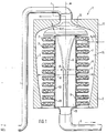
- FIG. 1 shows in section a filter device 1, the filter housing 2 of which has filter disks 7 parallel to one another in its interior 14.
- the filter device 1 is arranged upright in the filter section, and an inlet 4 for the plastic melt, which flows in, for example, from a screw extruder, not shown, runs outside the filter housing 2 and opens into the filter housing 2 from above.
- a drain 5 is located on the bottom of the filter housing 2.
- a filter rod 6 is arranged centrally, on which the mutually parallel filter disks 7 are located.
- the filter disks 7 have an outer diameter of 178 to 305 mm, i.e. from 7 to 12 inches, and have a slice thickness on the order of 6 to 10 mm.
- a baffle plate 12 is arranged above the first filter disk 7, which forms a gap with a filter housing inner wall 3.
- the filter housing inner wall 3 encloses the interior 14 of the filter device 1, which works as a flow-through filter device.
- the plastic melt flowing through the inflow 4 into the filter device 1 flows down through the gap between the baffle plate 12 and the filter housing inner wall 3 and is divided into partial flows which flow through the individual filter disks 7.
- An inner diameter D of the filter housing 2 decreases in the direction of flow the plastic melt in accordance with the taper of the filter housing inner wall 3. As will be described in more detail below, the inner diameter D changes according to a function greater than a second root function.
- the filter discs 7 have the same outer disc diameter and the same inner disc diameter.
- An outer edge 8 of the individual filter disk 7 has a distance h a (x) from the inner wall 3 of the filter housing, which changes with the position coordinate x of the individual filter disk 7 (cf. FIG. 3).
- the partial flows flowing through the filter disks 7 enter a channel 15, in which the filter rod 6 is located and which is separated by the seals 13 and the inner edges 9 of the Filter disc 7 is limited.
- the plastic melt is filtered in the filter disks 7, so that only filtered plastic melt flows into the channel 15.
- a diameter d of the filter rod 6 decreases in the direction of flow of the plastic melt.
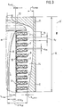
- FIG. 2 shows the preferred arrangement of the filter device 1, namely lying in the filter section, which delivers even better results than the arrangement according to FIG. 1 with regard to the flow profile and the uniform distribution of the partial flows of the plastic melt onto the individual filter disks 7.
- the filter device 1 is operated as a flow-through filter device, the horizontal inlet 4 and the horizontal outlet 5 being attached at the same height and in the center of the filter housing cover and base.
- the elements of the filter device which are identical to the elements of the filter device 1 according to FIG. 1 have the same reference numerals and will not be described again.
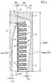
- the geometry of the filter device 1 is explained in more detail with reference to FIG. 3, which shows an enlarged partial section of the filter device 1 according to FIGS. 1 and 2.
- the position coordinate x represents the position of the individual filter disk 7 and runs in the direction of flow of the plastic melt, ie from top to bottom in FIG. 1 and from left to right in FIG.
- a distance a f from the top of a filter disk 7 to the top of an adjacent filter disk 7 is of the order of 6 to 13 mm, this distance also being equal to the sum of the disk thickness and the thickness of the seal 13.
- the disc thickness s d is 5 to 10 mm, while the thickness d fm of the filter medium of the individual filter disc is between 1 and 8 mm, in particular 2.5 to 3 mm.
- the filter disks 7 have the same size outer and inner diameters d ad and d id .
- the disc outer diameter is 178 to 305 mm, while the disc inner diameter is in the range of 38 to 85 mm.
- the minimum gap width h a min between the filter disc edge and the filter housing inner wall 3 is close to the filter housing base, while the maximum gap width h a max is close to a filter housing cover.
- the conditions behave at the distance between the filter rod 6 and the inner edge of the filter disk.
- the minimum gap width h i min is located near the filter housing cover, while the maximum gap width h i max is close to the filter housing base.
- the exponents ⁇ and ⁇ of the root function specify the curvature of the filter rod 6 and the filter housing inner wall 3.
- h a max 5.0 mm
- h a min 1.2 mm
- h i max 9.5 mm
- h i min 0.0 mm
- 1/2 d id 19.1 mm
- 1/2 d ad 89 mm.
- the gap width h a (x) is the distance between the outer edge of the filter disc 8 and the filter housing inner wall 3, depending on the position coordinate x in the direction of flow of the plastic melt.
- the preferred value for the geometric exponent ⁇ is 1/3, as already mentioned above.
- the filter device fulfills the requirement for low pressure loss and a small mean residence time, as was shown above with reference to FIG. 5.
- the main parameter for the low pressure loss and the shorter average residence time is the filter area or the number of disc filters. A large filter area reduces the pressure loss, but increases the average residence time.
- the suitable choice of the gap width h a (x) and h i (x) takes place in such a way that the most homogeneous throughput distribution over the individual filter disks and a narrow residence time spectrum of the melt flow are achieved.
- FIG. 6 shows filter pressure loss curves for a filter device 1 with 56 filter disks and the dimensions of FIG. 4 for the three known flow rates of 50 kg / hour, 100 kg / hour and 220 kg / hour.
- the total filter area of this filter device is approximately 2.30 m 2 .
- the filter device has a service life of approximately 84 hours at the high throughput of 220 kg / hour and a service life of approximately 162 at an average throughput of 150 kg / hour Hours. After these idle times, the filter device must either be replaced or the filter discs cleaned by backwashing in order to avoid an increase in pressure above the maximum permissible pressure drop.
- the gap width h i corresponds to the minimum gap width h i min and is equal to 0.
- the mean rod cross section is smaller than the left rod cross section and corresponds to a position coordinate 0 ⁇ x ⁇ 495.4 mm.
- the gap width h i (x) is greater than 0.
- the gap width h i (x) corresponds to the maximum gap width h i max and is 9.5 mm.
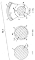
- This rod cross-section is the smallest and is located at the outlet of the filter device, ie at the bottom in FIG. 1 or at the right end of the filter device 1 in FIG. 2.
- the filter rod 6 has radial webs 10, the lengths of which increase in the flow direction of the plastic melt, as from middle and right rod cross section can be seen in Figure 7.
- the webs 10 serve as filter disk supports for the axial adjustment of the filter disks 7.
- the three webs 10 are kept very narrow in order to influence the flow cross sections in the channel 15 of the filter device 1 as little as possible.
- the individual flow cross sections in channel 15 are treated or considered as a flat column.
- the gap width h (r) and r are shown in Figure 1.
- the gap width h (r) between the filter housing inner wall and the baffle plate 12 is thus inversely proportional to the third root of the radial distance r from the center line m of the filter rod 6 or the filter device 1.
- the residence time is 13 sec and the pressure loss 0.3 bar in the gap between the baffle plate 12 and the filter housing head 11.
- the dwell time is 5 sec and the pressure loss in the filter device 1, for the case that this contains 56 filter discs 7 with a disc outer diameter d ad of 178 mm.
Landscapes
- Chemical & Material Sciences (AREA)
- Chemical Kinetics & Catalysis (AREA)
- Engineering & Computer Science (AREA)
- Mechanical Engineering (AREA)
- Extrusion Moulding Of Plastics Or The Like (AREA)
- Processing And Handling Of Plastics And Other Materials For Molding In General (AREA)
- Spinning Methods And Devices For Manufacturing Artificial Fibers (AREA)
Applications Claiming Priority (2)
| Application Number | Priority Date | Filing Date | Title |
|---|---|---|---|
| DE19618090 | 1996-05-06 | ||
| DE19618090A DE19618090A1 (de) | 1996-05-06 | 1996-05-06 | Filtervorrichtung zum gleichmäßigen Filtrieren von Kunststoffschmelzen |
Publications (2)
| Publication Number | Publication Date |
|---|---|
| EP0806281A1 true EP0806281A1 (fr) | 1997-11-12 |
| EP0806281B1 EP0806281B1 (fr) | 2000-04-12 |
Family
ID=7793441
Family Applications (1)
| Application Number | Title | Priority Date | Filing Date |
|---|---|---|---|
| EP97107267A Expired - Lifetime EP0806281B1 (fr) | 1996-05-06 | 1997-05-02 | Dispositif filtrant permettant la filtration homogène des matières plastiques fondues |
Country Status (5)
| Country | Link |
|---|---|
| US (1) | US5916443A (fr) |
| EP (1) | EP0806281B1 (fr) |
| JP (1) | JPH10102313A (fr) |
| KR (1) | KR970073679A (fr) |
| DE (2) | DE19618090A1 (fr) |
Cited By (6)
| Publication number | Priority date | Publication date | Assignee | Title |
|---|---|---|---|---|
| EP1199325A4 (fr) * | 2000-04-13 | 2003-07-16 | Teijin Ltd | Procede de production de polycarbonate et dispositif de filtration |
| WO2008052664A2 (fr) | 2006-10-31 | 2008-05-08 | Bayer Materialscience Ag | Procédé pour filtrer des matériaux substrats |
| DE102007007462A1 (de) | 2007-02-15 | 2008-08-21 | Bayer Materialscience Ag | Verwendung von Alumosilikaten zur Entfernung bzw. Reduzierung von fluoreszierenden Partikeln in Polycarbonat |
| JP2019536618A (ja) * | 2016-10-31 | 2019-12-19 | ウエストレイク ロングビュー コーポレイション | ポリマー溶融物のためのキャンドルフィルタ支持体及びプレートアセンブリ |
| CN114746244A (zh) * | 2019-11-28 | 2022-07-12 | 诺信公司 | 用于过滤流体特别是具有杂质的塑料熔体的设备以及用于这种流体的阀装置 |
| WO2023161479A1 (fr) * | 2022-02-28 | 2023-08-31 | Alfa Laval Corporate Ab | Agencement de filtre, système de manipulation de fluide et procédé |
Families Citing this family (16)
| Publication number | Priority date | Publication date | Assignee | Title |
|---|---|---|---|---|
| JP2001009214A (ja) * | 1999-06-30 | 2001-01-16 | Teijin Ltd | ポリカーボネート用濾過装置およびポリカーボネート製造方法 |
| US20030131791A1 (en) * | 2000-11-21 | 2003-07-17 | Schultz Carl L. | Multiple orifice applicator system and method of using same |
| DE10244292B4 (de) * | 2002-09-23 | 2008-06-12 | Boll & Kirch Filterbau Gmbh | Verwendung von Filterelementen in Rückspülfiltern |
| NZ539237A (en) * | 2002-10-09 | 2006-11-30 | Univ East Carolina | Frequency altered feedback for treating non-stuttering pathologies |
| US20050035051A1 (en) * | 2003-08-12 | 2005-02-17 | Mott Metallurgical Corporation | Extended area filter |
| US7361300B2 (en) | 2003-08-12 | 2008-04-22 | Mott Corporation | Method of making extended area filter |
| FI123096B (fi) * | 2004-10-29 | 2012-11-15 | Outotec Oyj | Suodatinasennelma näytteenottoa varten |
| JP2009202518A (ja) * | 2008-02-29 | 2009-09-10 | Toray Ind Inc | リーフディスクフィルタ組立体および熱可塑性樹脂シートの製造方法 |
| DE102010000925B4 (de) * | 2010-01-14 | 2012-04-19 | Kreyenborg Beteiligungen Und Verwaltungen Gmbh & Co. Kg | Siebträgerelement für eine Filtriereinrichtung mit wenigstens einer Siebkavität |
| EP3088157B1 (fr) * | 2015-04-30 | 2021-05-12 | Fimic S.r.l. | Filtre pour matière plastique |
| EP3308940B1 (fr) * | 2016-10-17 | 2025-03-05 | Next Generation Analytics GmbH | Système de filtre pour les fluides visqueux ou fortement visqueux, surtout plastique fondu et procédé de filtration des liquides visqueux ou fortement visqueux |
| JP6851847B2 (ja) * | 2017-02-10 | 2021-03-31 | 住友化学株式会社 | ポリマーフィルタ、ポリマーフィルムの製造方法およびポリマーフィルム |
| US11260570B2 (en) * | 2018-05-07 | 2022-03-01 | PSI-Polymer Systems, Inc. | Filtration apparatuses and screen changer devices for polymer processing and related methods |
| JP2022083576A (ja) * | 2020-11-25 | 2022-06-06 | 信越ポリマー株式会社 | 押出成形機のフィルタ装置 |
| KR102630345B1 (ko) * | 2021-09-16 | 2024-01-30 | 국민대학교 산학협력단 | 미세 섬유 포집 장치 |
| US20230340743A1 (en) * | 2022-04-22 | 2023-10-26 | Dama Manufacturing Limited | Water filter/screen |
Citations (7)
| Publication number | Priority date | Publication date | Assignee | Title |
|---|---|---|---|---|
| DE915490C (de) * | 1948-10-13 | 1954-07-22 | Algemene Kunstzijde Unie Nv | Filtriervorrichtung |
| DE3430992A1 (de) * | 1983-11-03 | 1985-06-13 | Hermann Berstorff Maschinenbau Gmbh, 3000 Hannover | Filtervorrichtung |
| US4572784A (en) * | 1983-10-28 | 1986-02-25 | Mordeki Drori | Multiple-disc filters |
| DE3644489C1 (de) * | 1986-12-24 | 1988-08-18 | Filtan Gmbh | Vorrichtung zur Abscheidung von Verunreinigungen |
| DE3941831C1 (fr) * | 1989-12-19 | 1990-10-18 | Kreyenborg Verwaltungen Und Beteiligungen Kg, 4400 Muenster, De | |
| DE4212928A1 (de) * | 1992-04-21 | 1993-10-28 | Gneuss Kunststofftechnik Gmbh | Filter für Kunststoffschmelzen |
| EP0658638A1 (fr) * | 1993-12-17 | 1995-06-21 | Zimmer Aktiengesellschaft | Tête à filer avec bougie filtrante |
Family Cites Families (13)
| Publication number | Priority date | Publication date | Assignee | Title |
|---|---|---|---|---|
| US3480706A (en) * | 1968-10-10 | 1969-11-25 | Du Pont | Spinning fiber-forming linear condensation polymer |
| CA989321A (en) * | 1970-07-17 | 1976-05-18 | Pcl Industries Limited | Method and aparatus for filtering flowable material |
| US3841489A (en) * | 1973-05-02 | 1974-10-15 | Kuss R And Co Inc | Fluid filter |
| DE2947685A1 (de) * | 1979-11-27 | 1981-07-23 | Hermann Berstorff Maschinenbau Gmbh, 3000 Hannover | Filtervorrichtung fuer schneckenextruder |
| GB2102691B (en) * | 1981-08-05 | 1985-01-09 | Cresta Tech | Rotary filter |
| US4453905A (en) * | 1983-06-01 | 1984-06-12 | Bennett Bobby B | Plastics recycling apparatus |
| NL192607C (nl) * | 1983-11-03 | 1997-11-04 | Berstorff Gmbh Masch Hermann | Zeefinrichting. |
| DE3419822C2 (de) * | 1984-05-26 | 1986-04-03 | Werner & Pfleiderer, 7000 Stuttgart | Filtervorrichtung für Schneckenextruder |
| JPH065855Y2 (ja) * | 1985-04-27 | 1994-02-16 | エスエムシ−株式会社 | ポリマ−ろ過装置 |
| DE3617370A1 (de) * | 1986-05-23 | 1987-12-10 | Hoechst Ag | Filtervorrichtung zum gleichmaessigen filtrieren von kunststoffschmelzen |
| US4964984A (en) * | 1989-06-14 | 1990-10-23 | Electromedics, Inc. | Blood filter |
| US5271838A (en) * | 1991-09-13 | 1993-12-21 | Pall Corporation | Filter assembly with filter elements separated by spacers |
| DE4338129A1 (de) * | 1993-11-08 | 1995-05-11 | Zimmer Ag | Verfahren zur Polymerschmelze-Filtration |
-
1996
- 1996-05-06 DE DE19618090A patent/DE19618090A1/de not_active Withdrawn
-
1997
- 1997-05-02 DE DE59701427T patent/DE59701427D1/de not_active Expired - Fee Related
- 1997-05-02 KR KR1019970016996A patent/KR970073679A/ko not_active Withdrawn
- 1997-05-02 EP EP97107267A patent/EP0806281B1/fr not_active Expired - Lifetime
- 1997-05-05 US US08/851,192 patent/US5916443A/en not_active Expired - Fee Related
- 1997-05-06 JP JP9131745A patent/JPH10102313A/ja not_active Withdrawn
Patent Citations (7)
| Publication number | Priority date | Publication date | Assignee | Title |
|---|---|---|---|---|
| DE915490C (de) * | 1948-10-13 | 1954-07-22 | Algemene Kunstzijde Unie Nv | Filtriervorrichtung |
| US4572784A (en) * | 1983-10-28 | 1986-02-25 | Mordeki Drori | Multiple-disc filters |
| DE3430992A1 (de) * | 1983-11-03 | 1985-06-13 | Hermann Berstorff Maschinenbau Gmbh, 3000 Hannover | Filtervorrichtung |
| DE3644489C1 (de) * | 1986-12-24 | 1988-08-18 | Filtan Gmbh | Vorrichtung zur Abscheidung von Verunreinigungen |
| DE3941831C1 (fr) * | 1989-12-19 | 1990-10-18 | Kreyenborg Verwaltungen Und Beteiligungen Kg, 4400 Muenster, De | |
| DE4212928A1 (de) * | 1992-04-21 | 1993-10-28 | Gneuss Kunststofftechnik Gmbh | Filter für Kunststoffschmelzen |
| EP0658638A1 (fr) * | 1993-12-17 | 1995-06-21 | Zimmer Aktiengesellschaft | Tête à filer avec bougie filtrante |
Cited By (8)
| Publication number | Priority date | Publication date | Assignee | Title |
|---|---|---|---|---|
| EP1199325A4 (fr) * | 2000-04-13 | 2003-07-16 | Teijin Ltd | Procede de production de polycarbonate et dispositif de filtration |
| WO2008052664A2 (fr) | 2006-10-31 | 2008-05-08 | Bayer Materialscience Ag | Procédé pour filtrer des matériaux substrats |
| DE102007007462A1 (de) | 2007-02-15 | 2008-08-21 | Bayer Materialscience Ag | Verwendung von Alumosilikaten zur Entfernung bzw. Reduzierung von fluoreszierenden Partikeln in Polycarbonat |
| JP2019536618A (ja) * | 2016-10-31 | 2019-12-19 | ウエストレイク ロングビュー コーポレイション | ポリマー溶融物のためのキャンドルフィルタ支持体及びプレートアセンブリ |
| CN114746244A (zh) * | 2019-11-28 | 2022-07-12 | 诺信公司 | 用于过滤流体特别是具有杂质的塑料熔体的设备以及用于这种流体的阀装置 |
| CN114746244B (zh) * | 2019-11-28 | 2024-03-15 | 诺信公司 | 用于过滤流体特别是具有杂质的塑料熔体的设备以及用于这种流体的阀装置 |
| US12318712B2 (en) | 2019-11-28 | 2025-06-03 | Nordson Corporation | Apparatus for filtering a fluid, in particular a plastic melt having impurities, and a valve arrangement for such a fluid |
| WO2023161479A1 (fr) * | 2022-02-28 | 2023-08-31 | Alfa Laval Corporate Ab | Agencement de filtre, système de manipulation de fluide et procédé |
Also Published As
| Publication number | Publication date |
|---|---|
| DE19618090A1 (de) | 1997-11-13 |
| EP0806281B1 (fr) | 2000-04-12 |
| DE59701427D1 (de) | 2000-05-18 |
| KR970073679A (ko) | 1997-12-10 |
| US5916443A (en) | 1999-06-29 |
| JPH10102313A (ja) | 1998-04-21 |
Similar Documents
| Publication | Publication Date | Title |
|---|---|---|
| EP0806281B1 (fr) | Dispositif filtrant permettant la filtration homogène des matières plastiques fondues | |
| EP0247468B1 (fr) | Dispositif filtrant permettant la filtration homogène des matières plastiques fondues | |
| DE2030618C3 (de) | Schrägklärer | |
| DE2349702C2 (de) | Verfahren und Vorrichtung zum Fraktionieren einer Suspension mittels Hydrozyklonen | |
| DE2116254C2 (de) | Vorrichtung zum kontinuierlichen Extrudieren hochviskoser Schmelzen | |
| DE3889573T2 (de) | Filterscheibe. | |
| WO1993007959A1 (fr) | Element ceramique de filtrage a courant tangentiel de liquides et de gaz | |
| DE2406649C2 (de) | Durchfluß-Kontrolleinheit | |
| WO1997020621A1 (fr) | Dispositif pour filtrer et separer des milieux en ecoulement | |
| EP0422137B1 (fr) | Filtre a spirale | |
| DE3783398T2 (de) | Filteranlage. | |
| DE3940334A1 (de) | Sieb fuer drucksortierer fuer fasersuspensionen | |
| DE2506855C3 (de) | Hochdruckreduzierventil | |
| EP0504836A1 (fr) | Broyeur agitateur | |
| DE10116039A1 (de) | Vorrichtung zum Filtern und Trennen von Strömungsmedien nach dem Prinzip der Ultrafiltration | |
| EP0207042B1 (fr) | Méthode pour puiser de l'eau exempte de sable d'un puits ainsi qu'un dispositif approprié | |
| EP3034146A1 (fr) | Bougie filtrante hydrodynamique optimisee | |
| EP0999888B1 (fr) | Dispositif filtrant | |
| DE3114212A1 (de) | "kaltabscheider zum ausscheiden von verunreinigungen aus einem fluessigmetall | |
| DE102007006811A1 (de) | Vorrichtung zum Filtrieren einer thermoplastischen Kunststoffschmelze | |
| DE2849528A1 (de) | In einem druckbehaelter angeordnetes zellendrehfilter | |
| DE2934117C2 (de) | Rückspülbares Filter | |
| WO1984003660A1 (fr) | Installation pour separer la partie liquide de la partie solide d'une barbotine ceramique | |
| EP0423527A1 (fr) | Dispositif pour la séparation de mélanges constitué par un empilement de membranes espacées les unes des autres | |
| DE10001907A1 (de) | Filtervorrichtung |
Legal Events
| Date | Code | Title | Description |
|---|---|---|---|
| PUAI | Public reference made under article 153(3) epc to a published international application that has entered the european phase |
Free format text: ORIGINAL CODE: 0009012 |
|
| AK | Designated contracting states |
Kind code of ref document: A1 Designated state(s): DE FR GB IT LU NL |
|
| 17P | Request for examination filed |
Effective date: 19971108 |
|
| 17Q | First examination report despatched |
Effective date: 19971215 |
|
| GRAG | Despatch of communication of intention to grant |
Free format text: ORIGINAL CODE: EPIDOS AGRA |
|
| GRAG | Despatch of communication of intention to grant |
Free format text: ORIGINAL CODE: EPIDOS AGRA |
|
| GRAH | Despatch of communication of intention to grant a patent |
Free format text: ORIGINAL CODE: EPIDOS IGRA |
|
| RAP1 | Party data changed (applicant data changed or rights of an application transferred) |
Owner name: MITSUBISHI POLYESTER FILM GMBH |
|
| GRAH | Despatch of communication of intention to grant a patent |
Free format text: ORIGINAL CODE: EPIDOS IGRA |
|
| GRAA | (expected) grant |
Free format text: ORIGINAL CODE: 0009210 |
|
| AK | Designated contracting states |
Kind code of ref document: B1 Designated state(s): DE FR GB IT LU NL |
|
| REF | Corresponds to: |
Ref document number: 59701427 Country of ref document: DE Date of ref document: 20000518 |
|
| ITF | It: translation for a ep patent filed | ||
| ET | Fr: translation filed | ||
| GBT | Gb: translation of ep patent filed (gb section 77(6)(a)/1977) |
Effective date: 20000615 |
|
| PLBE | No opposition filed within time limit |
Free format text: ORIGINAL CODE: 0009261 |
|
| STAA | Information on the status of an ep patent application or granted ep patent |
Free format text: STATUS: NO OPPOSITION FILED WITHIN TIME LIMIT |
|
| 26N | No opposition filed | ||
| REG | Reference to a national code |
Ref country code: GB Ref legal event code: IF02 |
|
| PGFP | Annual fee paid to national office [announced via postgrant information from national office to epo] |
Ref country code: FR Payment date: 20030410 Year of fee payment: 7 |
|
| PGFP | Annual fee paid to national office [announced via postgrant information from national office to epo] |
Ref country code: NL Payment date: 20030417 Year of fee payment: 7 |
|
| PGFP | Annual fee paid to national office [announced via postgrant information from national office to epo] |
Ref country code: GB Payment date: 20030430 Year of fee payment: 7 |
|
| PGFP | Annual fee paid to national office [announced via postgrant information from national office to epo] |
Ref country code: LU Payment date: 20030502 Year of fee payment: 7 |
|
| PGFP | Annual fee paid to national office [announced via postgrant information from national office to epo] |
Ref country code: DE Payment date: 20030531 Year of fee payment: 7 |
|
| PG25 | Lapsed in a contracting state [announced via postgrant information from national office to epo] |
Ref country code: LU Free format text: LAPSE BECAUSE OF NON-PAYMENT OF DUE FEES Effective date: 20040502 Ref country code: GB Free format text: LAPSE BECAUSE OF NON-PAYMENT OF DUE FEES Effective date: 20040502 |
|
| PG25 | Lapsed in a contracting state [announced via postgrant information from national office to epo] |
Ref country code: NL Free format text: LAPSE BECAUSE OF NON-PAYMENT OF DUE FEES Effective date: 20041201 Ref country code: DE Free format text: LAPSE BECAUSE OF NON-PAYMENT OF DUE FEES Effective date: 20041201 |
|
| GBPC | Gb: european patent ceased through non-payment of renewal fee |
Effective date: 20040502 |
|
| PG25 | Lapsed in a contracting state [announced via postgrant information from national office to epo] |
Ref country code: FR Free format text: LAPSE BECAUSE OF NON-PAYMENT OF DUE FEES Effective date: 20050131 |
|
| NLV4 | Nl: lapsed or anulled due to non-payment of the annual fee |
Effective date: 20041201 |
|
| REG | Reference to a national code |
Ref country code: FR Ref legal event code: ST |
|
| PG25 | Lapsed in a contracting state [announced via postgrant information from national office to epo] |
Ref country code: IT Free format text: LAPSE BECAUSE OF NON-PAYMENT OF DUE FEES;WARNING: LAPSES OF ITALIAN PATENTS WITH EFFECTIVE DATE BEFORE 2007 MAY HAVE OCCURRED AT ANY TIME BEFORE 2007. THE CORRECT EFFECTIVE DATE MAY BE DIFFERENT FROM THE ONE RECORDED. Effective date: 20050502 |