EP0806264B1 - Machine-outil à broche excentrable - Google Patents
Machine-outil à broche excentrable Download PDFInfo
- Publication number
- EP0806264B1 EP0806264B1 EP96810298A EP96810298A EP0806264B1 EP 0806264 B1 EP0806264 B1 EP 0806264B1 EP 96810298 A EP96810298 A EP 96810298A EP 96810298 A EP96810298 A EP 96810298A EP 0806264 B1 EP0806264 B1 EP 0806264B1
- Authority
- EP
- European Patent Office
- Prior art keywords
- slide
- machine tool
- spindle
- tool according
- workpiece
- Prior art date
- Legal status (The legal status is an assumption and is not a legal conclusion. Google has not performed a legal analysis and makes no representation as to the accuracy of the status listed.)
- Expired - Lifetime
Links
- 239000000463 material Substances 0.000 claims abstract description 3
- 238000003754 machining Methods 0.000 claims description 11
- 239000000314 lubricant Substances 0.000 claims description 5
- 238000002347 injection Methods 0.000 claims description 3
- 239000007924 injection Substances 0.000 claims description 3
- 239000007788 liquid Substances 0.000 claims description 2
- 230000001050 lubricating effect Effects 0.000 claims 1
- 238000006073 displacement reaction Methods 0.000 description 16
- 230000005540 biological transmission Effects 0.000 description 3
- 238000005461 lubrication Methods 0.000 description 3
- 238000010586 diagram Methods 0.000 description 2
- 229910001374 Invar Inorganic materials 0.000 description 1
- 239000002173 cutting fluid Substances 0.000 description 1
- 239000010730 cutting oil Substances 0.000 description 1
- 230000001419 dependent effect Effects 0.000 description 1
- 238000005553 drilling Methods 0.000 description 1
- 230000001939 inductive effect Effects 0.000 description 1
- 230000035515 penetration Effects 0.000 description 1
- 230000002028 premature Effects 0.000 description 1
Images

Classifications
-
- B—PERFORMING OPERATIONS; TRANSPORTING
- B23—MACHINE TOOLS; METAL-WORKING NOT OTHERWISE PROVIDED FOR
- B23Q—DETAILS, COMPONENTS, OR ACCESSORIES FOR MACHINE TOOLS, e.g. ARRANGEMENTS FOR COPYING OR CONTROLLING; MACHINE TOOLS IN GENERAL CHARACTERISED BY THE CONSTRUCTION OF PARTICULAR DETAILS OR COMPONENTS; COMBINATIONS OR ASSOCIATIONS OF METAL-WORKING MACHINES, NOT DIRECTED TO A PARTICULAR RESULT
- B23Q1/00—Members which are comprised in the general build-up of a form of machine, particularly relatively large fixed members
- B23Q1/25—Movable or adjustable work or tool supports
- B23Q1/44—Movable or adjustable work or tool supports using particular mechanisms
- B23Q1/56—Movable or adjustable work or tool supports using particular mechanisms with sliding pairs only, the sliding pairs being the first two elements of the mechanism
- B23Q1/60—Movable or adjustable work or tool supports using particular mechanisms with sliding pairs only, the sliding pairs being the first two elements of the mechanism two sliding pairs only, the sliding pairs being the first two elements of the mechanism
- B23Q1/62—Movable or adjustable work or tool supports using particular mechanisms with sliding pairs only, the sliding pairs being the first two elements of the mechanism two sliding pairs only, the sliding pairs being the first two elements of the mechanism with perpendicular axes, e.g. cross-slides
- B23Q1/621—Movable or adjustable work or tool supports using particular mechanisms with sliding pairs only, the sliding pairs being the first two elements of the mechanism two sliding pairs only, the sliding pairs being the first two elements of the mechanism with perpendicular axes, e.g. cross-slides a single sliding pair followed perpendicularly by a single sliding pair
-
- B—PERFORMING OPERATIONS; TRANSPORTING
- B23—MACHINE TOOLS; METAL-WORKING NOT OTHERWISE PROVIDED FOR
- B23Q—DETAILS, COMPONENTS, OR ACCESSORIES FOR MACHINE TOOLS, e.g. ARRANGEMENTS FOR COPYING OR CONTROLLING; MACHINE TOOLS IN GENERAL CHARACTERISED BY THE CONSTRUCTION OF PARTICULAR DETAILS OR COMPONENTS; COMBINATIONS OR ASSOCIATIONS OF METAL-WORKING MACHINES, NOT DIRECTED TO A PARTICULAR RESULT
- B23Q1/00—Members which are comprised in the general build-up of a form of machine, particularly relatively large fixed members
- B23Q1/25—Movable or adjustable work or tool supports
- B23Q1/44—Movable or adjustable work or tool supports using particular mechanisms
- B23Q1/50—Movable or adjustable work or tool supports using particular mechanisms with rotating pairs only, the rotating pairs being the first two elements of the mechanism
- B23Q1/54—Movable or adjustable work or tool supports using particular mechanisms with rotating pairs only, the rotating pairs being the first two elements of the mechanism two rotating pairs only
- B23Q1/5468—Movable or adjustable work or tool supports using particular mechanisms with rotating pairs only, the rotating pairs being the first two elements of the mechanism two rotating pairs only a single rotating pair followed parallelly by a single rotating pair
-
- Y—GENERAL TAGGING OF NEW TECHNOLOGICAL DEVELOPMENTS; GENERAL TAGGING OF CROSS-SECTIONAL TECHNOLOGIES SPANNING OVER SEVERAL SECTIONS OF THE IPC; TECHNICAL SUBJECTS COVERED BY FORMER USPC CROSS-REFERENCE ART COLLECTIONS [XRACs] AND DIGESTS
- Y10—TECHNICAL SUBJECTS COVERED BY FORMER USPC
- Y10S—TECHNICAL SUBJECTS COVERED BY FORMER USPC CROSS-REFERENCE ART COLLECTIONS [XRACs] AND DIGESTS
- Y10S82/00—Turning
- Y10S82/903—Balancing and centering
-
- Y—GENERAL TAGGING OF NEW TECHNOLOGICAL DEVELOPMENTS; GENERAL TAGGING OF CROSS-SECTIONAL TECHNOLOGIES SPANNING OVER SEVERAL SECTIONS OF THE IPC; TECHNICAL SUBJECTS COVERED BY FORMER USPC CROSS-REFERENCE ART COLLECTIONS [XRACs] AND DIGESTS
- Y10—TECHNICAL SUBJECTS COVERED BY FORMER USPC
- Y10T—TECHNICAL SUBJECTS COVERED BY FORMER US CLASSIFICATION
- Y10T82/00—Turning
- Y10T82/12—Radially moving rotating tool inside bore
- Y10T82/125—Tool simultaneously moving axially
-
- Y—GENERAL TAGGING OF NEW TECHNOLOGICAL DEVELOPMENTS; GENERAL TAGGING OF CROSS-SECTIONAL TECHNOLOGIES SPANNING OVER SEVERAL SECTIONS OF THE IPC; TECHNICAL SUBJECTS COVERED BY FORMER USPC CROSS-REFERENCE ART COLLECTIONS [XRACs] AND DIGESTS
- Y10—TECHNICAL SUBJECTS COVERED BY FORMER USPC
- Y10T—TECHNICAL SUBJECTS COVERED BY FORMER US CLASSIFICATION
- Y10T82/00—Turning
- Y10T82/16—Severing or cut-off
- Y10T82/16229—Interrelated means for tool infeed and circumrotation
- Y10T82/16262—Infeed cam disk rotation geared to tool holder rotation
- Y10T82/16295—Infeed cam disk rotation geared to tool holder rotation including centrifugal balancing means
-
- Y—GENERAL TAGGING OF NEW TECHNOLOGICAL DEVELOPMENTS; GENERAL TAGGING OF CROSS-SECTIONAL TECHNOLOGIES SPANNING OVER SEVERAL SECTIONS OF THE IPC; TECHNICAL SUBJECTS COVERED BY FORMER USPC CROSS-REFERENCE ART COLLECTIONS [XRACs] AND DIGESTS
- Y10—TECHNICAL SUBJECTS COVERED BY FORMER USPC
- Y10T—TECHNICAL SUBJECTS COVERED BY FORMER US CLASSIFICATION
- Y10T82/00—Turning
- Y10T82/25—Lathe
- Y10T82/2529—Revolvable cutter heads
-
- Y—GENERAL TAGGING OF NEW TECHNOLOGICAL DEVELOPMENTS; GENERAL TAGGING OF CROSS-SECTIONAL TECHNOLOGIES SPANNING OVER SEVERAL SECTIONS OF THE IPC; TECHNICAL SUBJECTS COVERED BY FORMER USPC CROSS-REFERENCE ART COLLECTIONS [XRACs] AND DIGESTS
- Y10—TECHNICAL SUBJECTS COVERED BY FORMER USPC
- Y10T—TECHNICAL SUBJECTS COVERED BY FORMER US CLASSIFICATION
- Y10T82/00—Turning
- Y10T82/26—Work driver
Definitions
- the present invention relates to a machine tool, in particular a lathe, having a spindle provided with a workpiece or a tool holder eccentric relative to the axis of rotation of the spindle according to the preamble of claim 1.
- a machine tool working in rotation cannot generally machine only parts with cylindrical or conical surfaces concentric and coaxial, i.e. the axes of rotation of the various spans are all aligned on a main longitudinal axis.
- This requires many manipulations, possibly loosening and new workpiece tightening, operations generally impractical or very difficult to realize by automatic means. Such manipulations influence negatively on the machining precision as well as on the rate of job.
- EP-A-0.486.992 describes a machining center on which the axis of rotation of the spindle is eccentric with respect to the machine frame. This machine could not easily machine parts as described upper.
- GB-1,244,703 shows a device in which the displacement of the tool holder relative to the axis of rotation of the spindle is effected only on a curve; so we cannot reach any point from the plane perpendicular to the axis of rotation of the spindle.
- Application DE-A-1.95.11.420 describes a lathe whose spindle is suitable to be offset by a fixed value relative to the main machining axis. Such a machine can therefore only machine a part having a single span eccentrically. On the other hand, the offset is fixed and is therefore neither adjustable nor programmable.
- the machine tool of EP 0 791 428 A1 has a spindle and a slide capable of being moved along an axis perpendicular to the main axis; on the other hand it has no means for limiting the transmission of forces due to forces centrifugal on the machine shaft.
- the object of the invention is therefore to propose a machine tool free from the aforementioned drawbacks of prior art machines and having a spindle provided with a tool holder or a workpiece holder, capable of being offset by any value between given limits, along an axis perpendicular to the axis of rotation of the spindle.
- Another object of the invention is to propose a machine tool having a spindle provided with means for compensating for the unbalance created by the offset of the workpiece or tool holder.
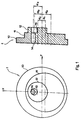
- the part 1 of FIG. 1 comprises a first cylindrical seat 10 having a certain diameter; on this first bearing 10, there is a second cylindrical bearing 11 whose diameter is less than that of the first bearing and whose longitudinal axis is offset by a value - X 1 relative to the longitudinal axis of the bearing 10
- a third bearing 12 is machined on the preceding bearing, also having a smaller diameter and an offset + X 2 relative to the longitudinal axis of the first bearing.
- the part 1 may also include a bore 13, the longitudinal axis of which is also offset by a value + X 3 as well as a through hole 14 whose longitudinal axis is offset by + X 4 .
- the part 1 shown here by way of example is produced solely from turning, boring and drilling operations, but it is understood that all the other machining operations that can be carried out on a lathe can be carried out, for example machining of cones, grooves, etc., having their longitudinal axis offset along the X axis.
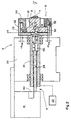
- FIG. 2 shows a block diagram of a machine tool 2, particularly of an eccentric clamping lathe, details of execution being shown in the following figures.
- the lathe 2 of which only a portion is shown in particular comprises a headstock 20 in which a shaft 21, driven by a motor 22, rotates a workpiece spindle 23.
- the spindle 23 has a general shape of bell, having its opening towards the right of the figure, respectively towards the workpiece 1.
- a slide 3 supporting the workpiece 1, is able to move along the axis of the X.
- the slide 3 preferably comprises a bottom portion 30 pierced with an oblique hole 31. The movement control of the slide 3 is obtained by displacement control means 4.
- These means 4 can consist of a tie rod 40, capable of sliding longitudinally inside a bore 24 made in the shaft 21, the movement of the tie rod 40 being controlled by an appropriate means, preferably a digital axis 41 connected on the one hand to the headstock 20 of the turn and secondly to one end of the tie rod 40.
- the other end of the tie rod 40 comprises an oblique bearing 42, making an angle ⁇ with the longitudinal axis of the lathe, said oblique bearing 42 being engaged and being able to slide in the oblique hole 31.
- the sliding of the oblique bearing 42 in the oblique hole 31 causes a displacement of the slide 3 along the axis X, respectively a decentering of the workpiece 1 relative to the main longitudinal axis of the lathe.
- a sensor 43 makes it possible to control the value of the displacement Z i as a function of the desired offset X i .
- a first spring 32, arranged between the spindle 23 and the slide 3 makes it possible to stabilize the position of the latter.
- the total possible displacement of the slide 3 relative to the pin 23 is given by the difference between the inside diameter of the bell of the pin 23 and the outside diameter of the slide 3.
- the tie In order to be able to control the movement of the slide 3 over a maximum distance, the tie must therefore be able to move a distance equivalent to this difference in diameters divided by tg ⁇ ., the bottom portion 30 of the slider 3 must be dimensioned so that the oblique bearing 42 remains constantly engaged in the oblique hole 31.
- balancing means 5 which can be composed of a massive piece, here a crown 50, having a certain mass and capable of also moving along the X axis, but according to a direction opposite to the movement of the slide 3.
- a set of levers 51 allows this relative movement of the crown 50 relative to the slide 3.
- the mass of the crown will be adjusted to be worth the previous value M, for example by adding screws in threads provided for this purpose in the crown 50 and the set of levers 51 will be determined to cause a displacement of the crown 50 of the same value but in the opposite direction to that commanded with the slide 3. It would also be possible to provide that the mass the crown 50 is different from the mass M of the slide 3 and the workpiece; in this case, the controlled displacement of the crown will be calculated so that the product of the mass of the crown 50 by its displacement is equal to the product of the mass M by the displacement of the slide 3.
- a second spring 52 stabilizes the position of the crown 50. The decentering of the slide 3 and of the crown 50 causes centrifugal forces also referring to the shaft 21.
- the constants of the springs 32 and 52 are chosen so that for a given offset and a given speed of rotation of the spindle 23, the force exerted by each spring is slightly greater than the centrifugal force exerted by the element which it repels. In this way, the forces exerted on the shaft 21 and the tie rod 40 are minimized. Since the movement control system of the slide 3 is in rotation with the spindle 23, it may be advantageous to arrange the movement control of the tie rod 40, here for example in the form of a digital axis 41, to the other end of this part in order to ensure a secure transmission of the signal and of the energy necessary for this movement command.
- the tie rod 40 is preferably made of a material with a very low coefficient of thermal expansion, such as invar for example.
- An eccentric clamping lathe as described above makes it possible to carry out turning operations with offset axes, the axes of said operations being aligned on the X axis.
- FIG 3 is a section along a plane perpendicular to the axis of decentering X, we can see some details of the pin 23 and the articulation of the slide 3 and the crown 50. The details d 'execution are not all shown so as not to overload the figure.
- the shaft 21 rotates the spindle 23.
- the tie rod 40 is able to move along the axis Z, as indicated above the oblique bearing 42 being engaged in the oblique hole 31 of the crown 3.
- Two pairs of needle bearings linear 33 allow the sliding of the slide 3 relative to the spindle 23.
- the crown 50 can slide along two cylindrical rods 25 disposed on both sides of the spindle 23. Only one of said rods 25 is shown on the right of the figure.
- the lever 51 able to pivot around an axis 26 fixed to the spindle 23.
- a similar lever is also found on the other side of the spindle 23.
- the operation of said levers 51 is shown in Figure 4.
- the slide 3 has an opening 36 opposite the lever 51, while the crown 50 has a corresponding opening 53.
- a displacement of a value X i , in a direction or in the other, controlled by the slide 3 rotates the lever 51 about its axis 26 and therefore drives the crown 50 of a corresponding movement in the opposite direction.
- the slide 3 has moved according to the maximum value of its possible displacement, having driven the crown 50 also according to its maximum possible displacement. It would also be possible to provide that the displacement transmission ratio is not 1: 1 as in the figure, but is inversely proportional to the masses of the elements to be moved. As indicated above, the crown 50 slides along the rods 25.
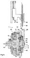
- Figure 5 shows a sectional view of a portion of the slide 3 showing the fixing device 6 for the workpiece 1.
- This is clamped by a conventional clamp 60 springing out, the bottom of the part 1 being supported on a stop.
- a portion of the outer surface of this clamp has a cone 61.
- a clamping piece 62 having a conical inner surface is axially displaceable and comes to tighten or loosen the clamp 60 according to its axial position.
- the clamping piece is held to the right of the figure, according to the position which clamps the clamp 60, by means of a plurality of springs 63 regularly arranged in a circle around the main longitudinal axis of the tower.
- the spindle is brought into a position determined angular such that an air intake orifice 64 is arranged in face of a compressed air injection nozzle 65 disposed on a fixed slide on the one hand to the headstock 20 and able to allow a displacement of the nozzle 65 in direction of the intake port 64.
- the air intake port 64 is in connection with an air chamber 66 also arranged in a circle around the axis main longitudinal of the tour. This air chamber 66 is arranged on one side a wall 67 acting as a piston, the other side of which rests on the springs 63, said wall forming part of the clamping piece 62.
- the nozzle 65 When the spindle is stopped in the desired position, the nozzle 65 is lowered and its end is introduced into the intake port 64; compressed air is then injected which spreads in the air chamber 66 and pushes back the wall 67, respectively the clamping piece 62 backwards, opposing the force exerted by the springs 63, which releases the clamp 60 and the workpiece 1.
- the inlet 64 is provided with a spring-loaded valve which can be actuated by the end of the nozzle 65, which prevents the penetration of liquid machining or chips in the air circuit of the fixing device 6.
- a clamping or loosening control device of the clamp 60 can also be mounted, for example next to the nozzle 65.
- This device consists of a jumper 68, fixed to the clamping piece 62, and a detector 69, for example a inductive sensor, approached to the jumper 68 when approaching the nozzle 65.
- a detector 69 for example a inductive sensor
- the machining program is informed of the status of tightening or loosening of the clamp 60.
- Such a fixing device is particularly well suited to the eccentric clamping lathe described previously, but it can also easily be installed on a machine tool or a conventional tour.
- the lubrication device 7 is constituted as shown in Figure 5; it consists of a nozzle 70, arranged on the same support as nozzle 65 or another support and lowering at the same time what.
- a lubricant inlet port 71 is arranged on the pin 23, in look of the nozzle 70 and is connected by pipes 72 bringing the product lubricant to the tie rod 40, from where it is distributed to the parts to be lubricated. So the lubrication is only completed when the machine is stopped during a change of workpiece. In this way, safe lubrication is provided at the tie rod 40 as well as at its oblique portion 42, allowing that the eccentricity of the slide 3 is controlled when the pin 23 is in rotation.
- a pipe 44 passes through longitudinally the tie rod 40 as well as the oblique portion 42 in order to bring a cutting fluid, which is expelled through pipes provided for this purpose at through the slide 3, respectively the clamping device 6 so prevent machining chips from entering the device and block the movements of the slide 3 and of the crown 50.
Landscapes
- Engineering & Computer Science (AREA)
- Mechanical Engineering (AREA)
- Turning (AREA)
- Gripping On Spindles (AREA)
- Auxiliary Devices For Machine Tools (AREA)
Description
Claims (15)
- Machine-outil (2) comportant notamment une broche (23) en rotation autour d'un axe principal, ladite broche pouvant être une broche porte-pièce ou une broche porte-outil, ladite broche (23) comportant un coulisseau (3) portant la pièce à usiner (1) ou l'outil d'usinage, ledit coulisseau étant apte à être excentrée par rapport audit axe principal, l'excentrage pouvant être obtenu de manière continue et comprenant n'importe quelle coordonnée (Xi) le long d'un axe perpendiculaire audit axe principal, ledit coulisseau étant apte à se déplacer le long dudit axe perpendiculaire audit axe principal, caractérisée en ce qu'un premier ressort (32) est disposé entre la broche (23) et le coulisseau (3), la constant dudit ressort étant choisie de manière à ce que sa force de pression soit toujours supérieure à la force centrifuge exercée par le coulisseau excentré.
- Machine-outil, selon la revendication 1, caractérisée en ce que le coulisseau (3) est commandé en déplacement au moyen d'un tirant (40) disposé dans un logement longitudinal (24) de l'arbre d'entraínement (21) de la broche (23), ledit tirant comportant à son extrémité proche dudit coulisseau (3) une portée oblique (42) engagée dans et coopérant avec un trou oblique (31) aménagé dans une partie de fond (30) du coulisseau, un déplacement axial dudit tirant (40) entraínant un déplacement radial du coulisseau (3).
- Machine-outil selon la revendication 2, caractérisée en ce que l'autre extrémité du tirant (40) est entraínée en déplacement axial au moyen d'un axe numérique (41), la valeur de déplacement du tirant étant contrôlée par un capteur (43).
- Machine-outil selon l'une des revendications 2 ou 3, caractérisée en ce que le tirant (40) est constitué en un matériau à faible coefficient de dilatation thermique.
- Machine-outil selon l'une des revendications précédentes, caractérisée en ce que l'excentrage du coulisseau (3), respectivement de la pièce à usiner (1), est commandé lorsque la broche (23) est en rotation.
- Machine-outil selon l'une des revendications précédentes, caractérisée en ce qu'elle comporte en outre des moyens d'équilibrage (5) aptes à compenser le balourd créé par l'excentrage du coulisseau (3) et de la pièce à usiner (1).
- Machine-outil selon la revendication 6, caractérisée en ce que les moyens d'équilibrage du balourd sont constitués d'une couronne (50) apte à se déplacer selon le même axe que le coulisseau (3) mais en sens opposé.
- Machine-outil selon la revendication 7, caractérisée en ce que le déplacement de la couronne (50) est commandé par au moins un levier (51) pivotant autour d'un axe (26) fixé à la broche (23), une première extrémité dudit levier étant engagée dans une ouverture (36) aménagée dans le coulisseau (3) l'autre extrémité dudit levier étant engagée dans une autre ouverture (53) aménagée dans la couronne (50).
- Machine-outil selon l'une des revendications 7 ou 8, caractérisée en ce que la masse de la couronne est ajustable de manière à égaliser la masse du coulisseau (3) ainsi que de la pièce à usiner (1), la valeur du déplacement dans un sens de la couronne (50) étant égale et opposée à la valeur de l'excentrage du coulisseau (3).
- Machine-outil selon l'une des revendications 7 à 9, caractérisée en ce qu'un deuxième ressort (52) est disposé entre la broche (23) et la couronne (50), la constante dudit ressort étant choisie de manière à ce que sa force de pression soit toujours supérieure à la force centrifuge exercée par la couronne (50) excentrée.
- Machine-outil selon l'une des revendications précédentes, caractérisée en ce que la pièce à usiner (1) est maintenue dans une pince circulaire à ressort (60) montée sur le coulisseau (3) et comportant une portion de surface extérieure conique (61), une pièce de serrage (62) déplaçable axialement entourant ladite pince (60) et comportant une surface conique coopérant avec la surface conique (61) de la pince (60) pour son serrage, le serrage de la pièce de serrage (62) contre la pince (60) étant obtenu au moyen d'une pluralité de ressorts (63), le desserrage étant obtenu au moyen d'air comprimé en provenance d'une buse d'injection (65), déplaçable radialement sur une poupée (20) de la machine-outil, ladite buse (65) étant engagée, lorsque la broche (23) n'est pas en rotation, dans un orifice d'admission d'air (64) disposé sur le coulisseau (3) afin d'injecter de l'air sous pression dans une chambre d'air (66) disposée dans une paroi (67) de ladite pièce de serrage (62), l'air sous pression s'opposant à la force exercée par les ressorts (63) afin de desserrer la pince (60) et de libérer la pièce à usiner (1).
- Machine-outil selon la revendication 11, caractérisée en ce qu'elle comporte en outre des moyens permettant de contrôler l'état serré ou desserré de la pince de serrage (60), constitués d'un cavalier (68) fixé à ladite pince et d'un détecteur de position (69) dudit cavalier.
- Machine-outil selon une des revendications 5-12 précédentes, caractérisée en ce qu'elle comporte en outre des moyens de lubrification (7) du tirant (40), constitués d'une buse d'injection de lubrifiant (70) déplaçable radialement sur la poupée (20) de la machine-outil, ladite buse (70) étant engagée, lorsque la broche (23) n'est pas en rotation, dans un orifice d'admission de lubrifiant (71) disposé sur la broche, afin d'injecter du lubrifiant dans une canalisation (72) reliée au logement (31,24) du tirant (40).
- Machine-outil selon une des revendications 5-13 précédentes, caractérisée en ce que le tirant (40) ainsi que la portée oblique (42) comportent une canalisation (44) pour le passage d'un liquide d'usinage.
- Machine-outil selon l'une des revendications précédentes, caractérisée en ce qu'elle constitue un tour.
Priority Applications (5)
| Application Number | Priority Date | Filing Date | Title |
|---|---|---|---|
| DE69621321T DE69621321T2 (de) | 1996-05-10 | 1996-05-10 | Werkzeugmaschine mit Exzenterspindel |
| AT96810298T ATE217828T1 (de) | 1996-05-10 | 1996-05-10 | Werkzeugmaschine mit exzenterspindel |
| EP96810298A EP0806264B1 (fr) | 1996-05-10 | 1996-05-10 | Machine-outil à broche excentrable |
| US08/837,798 US6128985A (en) | 1996-05-10 | 1997-04-22 | Machine tool |
| JP11827997A JP3361959B2 (ja) | 1996-05-10 | 1997-05-08 | 偏心可能なスピンドルを有する工作機械 |
Applications Claiming Priority (1)
| Application Number | Priority Date | Filing Date | Title |
|---|---|---|---|
| EP96810298A EP0806264B1 (fr) | 1996-05-10 | 1996-05-10 | Machine-outil à broche excentrable |
Publications (2)
| Publication Number | Publication Date |
|---|---|
| EP0806264A1 EP0806264A1 (fr) | 1997-11-12 |
| EP0806264B1 true EP0806264B1 (fr) | 2002-05-22 |
Family
ID=8225604
Family Applications (1)
| Application Number | Title | Priority Date | Filing Date |
|---|---|---|---|
| EP96810298A Expired - Lifetime EP0806264B1 (fr) | 1996-05-10 | 1996-05-10 | Machine-outil à broche excentrable |
Country Status (5)
| Country | Link |
|---|---|
| US (1) | US6128985A (fr) |
| EP (1) | EP0806264B1 (fr) |
| JP (1) | JP3361959B2 (fr) |
| AT (1) | ATE217828T1 (fr) |
| DE (1) | DE69621321T2 (fr) |
Families Citing this family (19)
| Publication number | Priority date | Publication date | Assignee | Title |
|---|---|---|---|---|
| ATE392971T1 (de) * | 1999-09-30 | 2008-05-15 | Kummer Freres Sa | Bearbeitungskopf |
| DE10019775A1 (de) * | 2000-04-20 | 2001-10-31 | Index Werke Kg Hahn & Tessky | Werkzeugmaschine und Werkstückspannfutter |
| US7029209B2 (en) | 2000-12-18 | 2006-04-18 | Cardemon, Inc. | Slidable boring tool with fine adjustment |
| AU2002231037A1 (en) | 2000-12-18 | 2002-07-01 | Cardemon Inc., D/B/A Car-Tec Company | Adjustment method and apparatus for a boring tool |
| JP4639488B2 (ja) * | 2001-02-15 | 2011-02-23 | オークマ株式会社 | 工作機械のチャック装置 |
| US8256092B1 (en) | 2008-01-30 | 2012-09-04 | Makino Inc. | Method for helical boring |
| GB0814828D0 (en) * | 2008-08-14 | 2008-09-17 | In Situ Oilfield Services Ltd | Chuck device and method |
| IT1396153B1 (it) * | 2009-06-11 | 2012-11-16 | Ivanova | Unita' portautensile con bilanciamento automatico delle masse eccentriche |
| JP5543193B2 (ja) * | 2009-12-24 | 2014-07-09 | 株式会社北川鉄工所 | 偏芯チャック装置およびワークの偏芯方法 |
| TWM415011U (en) * | 2011-04-29 | 2011-11-01 | Autogrip Machinery Co Ltd | Air-infilling device of pneumatic chuck |
| KR101542814B1 (ko) * | 2011-07-19 | 2015-08-07 | 마우저-베르케 오베른도르프 마쉬넨바우 게엠베하 | 재조절 시스템 |
| US8770222B2 (en) * | 2012-06-29 | 2014-07-08 | Autogrip Machinery Co., Ltd. | Air pump assembly for a power chuck |
| JP6207568B2 (ja) * | 2015-10-20 | 2017-10-04 | 株式会社オーエム製作所 | 偏心量調整機構を備えた旋盤 |
| CN107225413B (zh) * | 2017-08-01 | 2023-09-01 | 中航西飞汉中航空零组件制造有限公司 | 一种数控车床用车削偏心零件的定位夹紧装置 |
| US10569341B2 (en) * | 2018-07-30 | 2020-02-25 | Lintech | Contouring head |
| CN111168096B (zh) * | 2020-01-10 | 2020-11-27 | 刘澄 | 一种钻孔机 |
| DE102020002421A1 (de) * | 2020-04-22 | 2021-10-28 | Niles-Simmons Industrieanlagen Gmbh | Verfahren und Vorrichtung zur Ermittlung von Zentren eines in einer Werkzeugmaschine drehbar eingespannten Werkstückes mit einem freien Konturabschnitt im Innenraum |
| CN117260515B (zh) * | 2023-11-22 | 2024-02-13 | 北京特思迪半导体设备有限公司 | 抛光机的动态联动控制方法 |
| CN117921398B (zh) * | 2024-01-31 | 2025-04-18 | 嘉兴市高照金属制品有限公司 | 伺服变位金属斜盘座加工工装 |
Citations (1)
| Publication number | Priority date | Publication date | Assignee | Title |
|---|---|---|---|---|
| EP0791428A1 (fr) * | 1996-02-20 | 1997-08-27 | Danobat, S. Coop | Poupée porte-pièces avec un plateau excentrique |
Family Cites Families (23)
| Publication number | Priority date | Publication date | Assignee | Title |
|---|---|---|---|---|
| US32211A (en) * | 1861-04-30 | Coal-sieteb | ||
| CH504932A (de) * | 1969-07-04 | 1971-03-31 | Vyzk Ustav Mech | Einrichtung zum Erzeugen einer exzentrischen Kreisbewegung eines Werkzeuges |
| AT321062B (de) * | 1973-06-27 | 1975-03-10 | Gfm Fertigungstechnik | Werkzeugmaschine zur spanabhebenden Bearbeitung von Kurbelwellen od.dgl. |
| US3881735A (en) * | 1974-03-13 | 1975-05-06 | Warner Swasey Co | Workholder |
| US4040315A (en) * | 1976-05-24 | 1977-08-09 | The Valeron Corporation | Machining cross-feed head counterweight system |
| JPS6031989B2 (ja) * | 1976-08-11 | 1985-07-25 | ト−ヨ−カネツ株式会社 | 地下埋設タンクの構築方法 |
| USRE32211E (en) | 1978-07-24 | 1986-07-22 | Devlieg Machine Company | Machine tool and method |
| DE3320129C1 (de) * | 1983-06-03 | 1984-10-11 | Aeg-Elotherm Gmbh, 5630 Remscheid | Verfahren und Maschinen zum Formschleifen von gesenkartig ausgebildeten und als Patrize oder Matrize verwendbaren Werkstuecken,insbesondere Grafitelektroden,fuer die funkenerosive Bearbeitung von Werkstuecken |
| DE3406490A1 (de) * | 1984-02-23 | 1985-08-29 | GTE Valeron Corp. (eine Gesellschaft n.d.Ges.d. Staates Delaware), Troy, Mich. | Auswechselbarer werkzeugkopf fuer eine numerisch gesteuerte werkzeugmaschine |
| US4899628A (en) * | 1988-06-13 | 1990-02-13 | Amca International Corporation | Dynamically compensating counterbalance |
| DE3828162A1 (de) * | 1988-08-19 | 1990-03-08 | Roehm Guenter H | Kraftbetaetigtes backenspannfutter fuer exzentrisch zu spannende werkstuecke |
| US4895058A (en) * | 1988-10-06 | 1990-01-23 | The Olofsson Corporation | Eccentric spindle |
| DE4025932A1 (de) * | 1989-09-09 | 1991-03-28 | Komet Stahlhalter Werkzeug | Werkzeugkopf fuer den einsatz in werkzeugmaschinen |
| IT1247783B (it) * | 1990-11-23 | 1994-12-30 | Vigel Spa | Macchina utensile ad asportazione di truciolo con testa portamandrino a tre gradi di liberta' |
| JPH04223815A (ja) * | 1990-12-26 | 1992-08-13 | Okuma Mach Works Ltd | 偏心量可変チャック |
| JPH0584605A (ja) * | 1991-09-27 | 1993-04-06 | Matsushita Electric Ind Co Ltd | ワーク保持装置 |
| JPH05256001A (ja) * | 1992-03-09 | 1993-10-05 | Nippon Steel Corp | 溝形折板屋根材の継手構造 |
| JP2996804B2 (ja) * | 1992-04-30 | 2000-01-11 | オークマ株式会社 | 偏心形状加工装置 |
| JPH06335803A (ja) * | 1993-05-28 | 1994-12-06 | Kuroda Precision Ind Ltd | 自動平衡装置付工具ヘッド |
| JPH0760516A (ja) * | 1993-08-23 | 1995-03-07 | Toyoda Mach Works Ltd | 中ぐり装置 |
| US5544556A (en) * | 1994-04-25 | 1996-08-13 | Cincinnati Milacron Inc. | Reversibly rotatable chuck with internal cam for shifting work axis |
| US5711196A (en) * | 1996-04-25 | 1998-01-27 | Hughes Electronics | Tooling apparatus and methodology for machining a blank having multiple spin centers |
| DE102008059139B4 (de) | 2008-11-26 | 2014-07-31 | Fissler Gmbh | Ventileinheit für einen Deckel eines Druckgefäßes |
-
1996
- 1996-05-10 DE DE69621321T patent/DE69621321T2/de not_active Expired - Fee Related
- 1996-05-10 AT AT96810298T patent/ATE217828T1/de not_active IP Right Cessation
- 1996-05-10 EP EP96810298A patent/EP0806264B1/fr not_active Expired - Lifetime
-
1997
- 1997-04-22 US US08/837,798 patent/US6128985A/en not_active Expired - Fee Related
- 1997-05-08 JP JP11827997A patent/JP3361959B2/ja not_active Expired - Fee Related
Patent Citations (1)
| Publication number | Priority date | Publication date | Assignee | Title |
|---|---|---|---|---|
| EP0791428A1 (fr) * | 1996-02-20 | 1997-08-27 | Danobat, S. Coop | Poupée porte-pièces avec un plateau excentrique |
Also Published As
| Publication number | Publication date |
|---|---|
| US6128985A (en) | 2000-10-10 |
| EP0806264A1 (fr) | 1997-11-12 |
| JP3361959B2 (ja) | 2003-01-07 |
| DE69621321D1 (de) | 2002-06-27 |
| DE69621321T2 (de) | 2003-01-02 |
| JPH1043916A (ja) | 1998-02-17 |
| ATE217828T1 (de) | 2002-06-15 |
Similar Documents
| Publication | Publication Date | Title |
|---|---|---|
| EP0806264B1 (fr) | Machine-outil à broche excentrable | |
| EP0213075B1 (fr) | Dispositif de serrage d'une pièce ou d'une barre de matériau à usiner | |
| FR2728818A1 (fr) | Porte-outil avec et sans outil, et ensemble a porte-outil et mandrin | |
| EP0161210A1 (fr) | Ravitailleur, notamment pour tour automatique, comprenant des blocs-paliers | |
| FR2637831A1 (fr) | Machine et outil pour le traitement de pieces a usiner par pierrage | |
| CA1289740C (fr) | Dispositif de montage a queue conique, en particulier au cone 7/24, a application cone et face pour attachements, porte-outils et outils | |
| EP0958105B1 (fr) | Dispositif d'usinage par enlevement de copeaux, a bloc massif et colonne coulissante, et machine incorporant ce dispositif | |
| CA2410521C (fr) | Tete a aleser | |
| FR3117056A1 (fr) | Outil d’usinage à double corps tubulaire, et procédé de fabrication d’un tel outil | |
| EP0457702B1 (fr) | Tête à aléser | |
| EP0346231B1 (fr) | Perceuse perfectionnée, notamment pour machine programmable | |
| WO2006027446A1 (fr) | Tete a aleser | |
| FR2659881A1 (fr) | Unite d'usinage a tete rotative portant des outils pivotants. | |
| EP0121638B1 (fr) | Dispositif guide barre pour tour multibroche | |
| EP1088613B1 (fr) | Tête d'usinage | |
| FR2476527A1 (fr) | Dispositif de retenue de pieces pour les operations de honage | |
| FR2566690A1 (fr) | Taraudeuse | |
| EP3307462B1 (fr) | Tour d'usinage et canon de guidage | |
| EP0363328B1 (fr) | Broche de machine-outil | |
| EP2170544B1 (fr) | Machine de decolletage | |
| CH647968A5 (en) | Rotary rest | |
| FR2594728A1 (fr) | Insert destine a etre implante dans les plaques de distributeurs de coulee continue et dispositif d'usinage d'alesage tronconique desdites plaques | |
| FR2473930A2 (fr) | Outillage pour la reparation, en particulier pour rodage d'un siege de robinet | |
| EP0211128B1 (fr) | Support des outils d'un tour automatique avec dispositif d'arrosage de ces outils | |
| FR2561147A1 (fr) | Outil de percage avec alimentation en agent de refroidissement |
Legal Events
| Date | Code | Title | Description |
|---|---|---|---|
| PUAI | Public reference made under article 153(3) epc to a published international application that has entered the european phase |
Free format text: ORIGINAL CODE: 0009012 |
|
| AK | Designated contracting states |
Kind code of ref document: A1 Designated state(s): AT CH DE FR GB IT LI NL |
|
| AX | Request for extension of the european patent |
Free format text: AL;LT;LV;SI |
|
| RBV | Designated contracting states (corrected) |
Designated state(s): AT CH DE FR GB IT LI NL |
|
| 17P | Request for examination filed |
Effective date: 19980316 |
|
| 17Q | First examination report despatched |
Effective date: 20010118 |
|
| GRAG | Despatch of communication of intention to grant |
Free format text: ORIGINAL CODE: EPIDOS AGRA |
|
| GRAG | Despatch of communication of intention to grant |
Free format text: ORIGINAL CODE: EPIDOS AGRA |
|
| GRAH | Despatch of communication of intention to grant a patent |
Free format text: ORIGINAL CODE: EPIDOS IGRA |
|
| GRAH | Despatch of communication of intention to grant a patent |
Free format text: ORIGINAL CODE: EPIDOS IGRA |
|
| GRAA | (expected) grant |
Free format text: ORIGINAL CODE: 0009210 |
|
| DAX | Request for extension of the european patent (deleted) | ||
| REF | Corresponds to: |
Ref document number: 217828 Country of ref document: AT Date of ref document: 20020615 Kind code of ref document: T |
|
| REG | Reference to a national code |
Ref country code: GB Ref legal event code: FG4D Free format text: NOT ENGLISH |
|
| REG | Reference to a national code |
Ref country code: CH Ref legal event code: EP |
|
| REF | Corresponds to: |
Ref document number: 69621321 Country of ref document: DE Date of ref document: 20020627 |
|
| REG | Reference to a national code |
Ref country code: CH Ref legal event code: NV Representative=s name: WILLIAM BLANC & CIE CONSEILS EN PROPRIETE INDUSTRI |
|
| GBT | Gb: translation of ep patent filed (gb section 77(6)(a)/1977) |
Effective date: 20020720 |
|
| PLBE | No opposition filed within time limit |
Free format text: ORIGINAL CODE: 0009261 |
|
| STAA | Information on the status of an ep patent application or granted ep patent |
Free format text: STATUS: NO OPPOSITION FILED WITHIN TIME LIMIT |
|
| 26N | No opposition filed |
Effective date: 20030225 |
|
| PGFP | Annual fee paid to national office [announced via postgrant information from national office to epo] |
Ref country code: CH Payment date: 20040426 Year of fee payment: 9 |
|
| PGFP | Annual fee paid to national office [announced via postgrant information from national office to epo] |
Ref country code: GB Payment date: 20040427 Year of fee payment: 9 |
|
| PGFP | Annual fee paid to national office [announced via postgrant information from national office to epo] |
Ref country code: NL Payment date: 20040429 Year of fee payment: 9 |
|
| PGFP | Annual fee paid to national office [announced via postgrant information from national office to epo] |
Ref country code: AT Payment date: 20040505 Year of fee payment: 9 |
|
| PGFP | Annual fee paid to national office [announced via postgrant information from national office to epo] |
Ref country code: DE Payment date: 20040510 Year of fee payment: 9 |
|
| PGFP | Annual fee paid to national office [announced via postgrant information from national office to epo] |
Ref country code: FR Payment date: 20040512 Year of fee payment: 9 |
|
| PG25 | Lapsed in a contracting state [announced via postgrant information from national office to epo] |
Ref country code: IT Free format text: LAPSE BECAUSE OF NON-PAYMENT OF DUE FEES Effective date: 20050510 Ref country code: GB Free format text: LAPSE BECAUSE OF NON-PAYMENT OF DUE FEES Effective date: 20050510 Ref country code: AT Free format text: LAPSE BECAUSE OF NON-PAYMENT OF DUE FEES Effective date: 20050510 |
|
| PG25 | Lapsed in a contracting state [announced via postgrant information from national office to epo] |
Ref country code: LI Free format text: LAPSE BECAUSE OF NON-PAYMENT OF DUE FEES Effective date: 20050531 Ref country code: CH Free format text: LAPSE BECAUSE OF NON-PAYMENT OF DUE FEES Effective date: 20050531 |
|
| PG25 | Lapsed in a contracting state [announced via postgrant information from national office to epo] |
Ref country code: NL Free format text: LAPSE BECAUSE OF NON-PAYMENT OF DUE FEES Effective date: 20051201 Ref country code: DE Free format text: LAPSE BECAUSE OF NON-PAYMENT OF DUE FEES Effective date: 20051201 |
|
| REG | Reference to a national code |
Ref country code: CH Ref legal event code: PL |
|
| GBPC | Gb: european patent ceased through non-payment of renewal fee |
Effective date: 20050510 |
|
| PG25 | Lapsed in a contracting state [announced via postgrant information from national office to epo] |
Ref country code: FR Free format text: LAPSE BECAUSE OF NON-PAYMENT OF DUE FEES Effective date: 20060131 |
|
| NLV4 | Nl: lapsed or anulled due to non-payment of the annual fee |
Effective date: 20051201 |
|
| REG | Reference to a national code |
Ref country code: FR Ref legal event code: ST Effective date: 20060131 |