EP1419852A1 - Unité de broche - Google Patents
Unité de broche Download PDFInfo
- Publication number
- EP1419852A1 EP1419852A1 EP02079754A EP02079754A EP1419852A1 EP 1419852 A1 EP1419852 A1 EP 1419852A1 EP 02079754 A EP02079754 A EP 02079754A EP 02079754 A EP02079754 A EP 02079754A EP 1419852 A1 EP1419852 A1 EP 1419852A1
- Authority
- EP
- European Patent Office
- Prior art keywords
- bearing
- shaft
- radial
- bearings
- spindle unit
- Prior art date
- Legal status (The legal status is an assumption and is not a legal conclusion. Google has not performed a legal analysis and makes no representation as to the accuracy of the status listed.)
- Withdrawn
Links
Images


Classifications
-
- B—PERFORMING OPERATIONS; TRANSPORTING
- B23—MACHINE TOOLS; METAL-WORKING NOT OTHERWISE PROVIDED FOR
- B23Q—DETAILS, COMPONENTS, OR ACCESSORIES FOR MACHINE TOOLS, e.g. ARRANGEMENTS FOR COPYING OR CONTROLLING; MACHINE TOOLS IN GENERAL CHARACTERISED BY THE CONSTRUCTION OF PARTICULAR DETAILS OR COMPONENTS; COMBINATIONS OR ASSOCIATIONS OF METAL-WORKING MACHINES, NOT DIRECTED TO A PARTICULAR RESULT
- B23Q3/00—Devices holding, supporting, or positioning work or tools, of a kind normally removable from the machine
- B23Q3/18—Devices holding, supporting, or positioning work or tools, of a kind normally removable from the machine for positioning only
- B23Q3/183—Centering devices
-
- B—PERFORMING OPERATIONS; TRANSPORTING
- B23—MACHINE TOOLS; METAL-WORKING NOT OTHERWISE PROVIDED FOR
- B23Q—DETAILS, COMPONENTS, OR ACCESSORIES FOR MACHINE TOOLS, e.g. ARRANGEMENTS FOR COPYING OR CONTROLLING; MACHINE TOOLS IN GENERAL CHARACTERISED BY THE CONSTRUCTION OF PARTICULAR DETAILS OR COMPONENTS; COMBINATIONS OR ASSOCIATIONS OF METAL-WORKING MACHINES, NOT DIRECTED TO A PARTICULAR RESULT
- B23Q1/00—Members which are comprised in the general build-up of a form of machine, particularly relatively large fixed members
- B23Q1/25—Movable or adjustable work or tool supports
- B23Q1/26—Movable or adjustable work or tool supports characterised by constructional features relating to the co-operation of relatively movable members; Means for preventing relative movement of such members
- B23Q1/38—Movable or adjustable work or tool supports characterised by constructional features relating to the co-operation of relatively movable members; Means for preventing relative movement of such members using fluid bearings or fluid cushion supports
- B23Q1/385—Movable or adjustable work or tool supports characterised by constructional features relating to the co-operation of relatively movable members; Means for preventing relative movement of such members using fluid bearings or fluid cushion supports in which the thickness of the fluid-layer is adjustable
-
- B—PERFORMING OPERATIONS; TRANSPORTING
- B23—MACHINE TOOLS; METAL-WORKING NOT OTHERWISE PROVIDED FOR
- B23Q—DETAILS, COMPONENTS, OR ACCESSORIES FOR MACHINE TOOLS, e.g. ARRANGEMENTS FOR COPYING OR CONTROLLING; MACHINE TOOLS IN GENERAL CHARACTERISED BY THE CONSTRUCTION OF PARTICULAR DETAILS OR COMPONENTS; COMBINATIONS OR ASSOCIATIONS OF METAL-WORKING MACHINES, NOT DIRECTED TO A PARTICULAR RESULT
- B23Q1/00—Members which are comprised in the general build-up of a form of machine, particularly relatively large fixed members
- B23Q1/70—Stationary or movable members for carrying working-spindles for attachment of tools or work
-
- B—PERFORMING OPERATIONS; TRANSPORTING
- B24—GRINDING; POLISHING
- B24B—MACHINES, DEVICES, OR PROCESSES FOR GRINDING OR POLISHING; DRESSING OR CONDITIONING OF ABRADING SURFACES; FEEDING OF GRINDING, POLISHING, OR LAPPING AGENTS
- B24B3/00—Sharpening cutting edges, e.g. of tools; Accessories therefor, e.g. for holding the tools
- B24B3/24—Sharpening cutting edges, e.g. of tools; Accessories therefor, e.g. for holding the tools of drills
- B24B3/247—Supports for drills
-
- B—PERFORMING OPERATIONS; TRANSPORTING
- B24—GRINDING; POLISHING
- B24B—MACHINES, DEVICES, OR PROCESSES FOR GRINDING OR POLISHING; DRESSING OR CONDITIONING OF ABRADING SURFACES; FEEDING OF GRINDING, POLISHING, OR LAPPING AGENTS
- B24B41/00—Component parts such as frames, beds, carriages, headstocks
- B24B41/04—Headstocks; Working-spindles; Features relating thereto
-
- B—PERFORMING OPERATIONS; TRANSPORTING
- B24—GRINDING; POLISHING
- B24B—MACHINES, DEVICES, OR PROCESSES FOR GRINDING OR POLISHING; DRESSING OR CONDITIONING OF ABRADING SURFACES; FEEDING OF GRINDING, POLISHING, OR LAPPING AGENTS
- B24B41/00—Component parts such as frames, beds, carriages, headstocks
- B24B41/06—Work supports, e.g. adjustable steadies
- B24B41/066—Work supports, e.g. adjustable steadies adapted for supporting work in the form of tools, e.g. drills
Definitions
- the present invention generally relates to the field of machine tools and more particularly a spindle unit comprising a rigid guide bearing a workpiece, used in particular for grinding cutting tools such than drills, strawberries or the like.
- Spindle units fitted to machine tools generally include a shaft fitted at one end with a clamp or jaws intended to clamp a workpiece.
- the shaft is rotatably mounted in a frame by means of two pairs of rolling bearings to support respectively the axial and radial forces applied to the shaft during the machining of said part.
- a most commonly encountered problems when using these spindle units lies in the difficulty of controlling the concentricity of the workpiece clamped in the clamp relative to the axis of rotation of the shaft, which in particular causes a orbital movement of the workpiece around said axis of rotation. This difficulty can be explained in particular by the inherent defects in the concentricity of the pliers hole relative to the axis of rotation of the spindle.
- clamping systems such pliers, high precision, whose concentricity defects are included in a range of 3 to 5 micrometers, solves the problem when the tolerances of the parts to be produced are of the same order. There is however a problem when the dimensional accuracy of the parts to be produced is less than the range supra.
- an additional rigid guide bearing supporting the part to machine and positioned beyond the gripper at a determined distance therefrom typically includes a V-shaped piece associated with a clamping finger which maintains the workpiece at the bottom of the V and thus considerably limits the orbital movement of the workpiece in the cantilevered part of the latter.
- the additional bearing prevents orbital movement near the free end of the workpiece, the clamp and / or the part of the workpiece located in the area between the clamp and the additional bearing must have a certain flexibility to allow this movement in this area. This solution cannot be therefore be considered only for workpieces of small dimensions, typically of the order of 3 mm in diameter, with which such deformation can be taken back by the parts.
- the main object of the present invention is therefore to remedy the drawbacks of the aforementioned prior art by providing a spindle unit which is simple and which allows machining of workpieces of any size with a lack of minimal concentricity.
- the invention also aims to provide such a spindle unit in allowing its operating conditions to be easily adapted to the dimensions and tolerances of the workpieces.
- the invention also aims to provide such a spindle unit which has a low manufacturing cost.
- the invention relates to a spindle unit comprising a frame, a shaft provided at one end with clamping means for clamping a workpiece machining, said shaft being rotatably mounted in said frame and supported radially by first and second radial bearings, said shaft being driven to rotation by motor means, said unit further comprising a third bearing disposed beyond said clamping means and capable of guiding said workpiece, characterized in that the first and second radial bearings are bearings hydrostatic and in that the second radial bearing situated on the side of the third bearing, is arranged to allow said shaft, in the region of said second bearing, a radial movement limited in a plane perpendicular to the axis of rotation of the shaft, the maximum amplitude of said radial movement being greater than that of any radial movement of the shaft which can be allowed by said first radial bearing.
- this spindle unit is the simplicity of the means used to perform machining with concentricity defects minimum. Indeed, hydrostatic bearing systems can be used in which it suffices to adjust the pressures appropriately to allow the desired limited radial movement in the plane perpendicular to the axis of rotation of the tree at the second level.
- the amplitude of said radial movement at the level of the first bearing is substantially zero and the amplitude of said radial movement at the level of the second bearing is at most of the order of ⁇ 0.03 mm around the middle position and preferably of the order of ⁇ 0.01 mm.
- FIGS. 1 and 2 show a spindle unit according to the invention, designated by the general numerical reference 1.
- the spindle unit 1 comprises a frame 2 comprising a bore 2a in which a shaft 4 is rotatably mounted by means of four bearings 6, 8, 10 and 12.
- the shaft 4 is supported radially by two bearings radial 6, 8 and is supported axially by two axial bearings 10,12.
- the bearings radial and axial 6, 8, 10, 12 are hydrostatic bearings well known to skilled in the art, although in an alternative embodiment of the invention the axial bearings may be bearings of the ball bearing type, the bearings radials remaining hydrostatic bearings
- the shaft 4 comprises at a first end, called the front end, clamping means 14 for clamping a workpiece 16.
- clamping means typically include a collet or a conventional collet with manual, hydraulic or compressed air control.
- the spindle unit 1 further comprises an additional bearing 18 arranged beyond the clamping means 14 and capable of guiding the workpiece 16 without play.
- the bearing 18 comprises a V-shaped groove 20, the bottom of the groove extending parallel to the axis of rotation of the shaft 4. The workpiece 16 rests thus on the inner flanks of the groove 20.
- the groove 20 is associated with a finger 22 which applies pressure to the workpiece 16 in order to keep it against said sides and thus ensures a play-free guide of the part 16.
- the bearing 18 is integral with a support 24 which can slide in the frame 2 of the spindle unit 1, along a direction parallel to the axis of rotation A-A 'of the shaft 4.
- the front end of the shaft 4 has a shoulder 26 having a rear face 26a.
- the shoulder 26 allows the shaft 4 to bear, via the rear face 26a, in a recess 28 formed in the front part of the frame 2.
- the bottom of the recess comprises an annular groove 30 in communication with a fluid source S via a line L 30 comprising a flow limiter 30a and a pressure limiter 32.
- a channel C 30 connects the groove 30 to an orifice (not shown) formed on the surface exterior of the frame and connected to the flow limiter 30a.
- the annular groove 30 thus forms with the rear face 26a of the shoulder 26 the axial hydrostatic bearing 12.
- the source of fluid comprises a reservoir R associated with a pump P which supplies the pressure relief valve 32.
- the shaft 4 has at its opposite end, called the rear end, a pulley 34 comprising a hub 34a, a flange 34b and a peripheral surface 34c.
- the hub 34a of the pulley is rotatably mounted on the rear end of the shaft 4.
- the peripheral surface 34c cooperates with a drive belt 36 connected to motor means (not shown) for the rotational drive of the shaft 4.
- the rear part of the frame 2 comprises an annular groove 38 also in communication with the fluid source S via a line L 38 comprising a flow limiter 38a and the pressure limiter 32
- a channel C 38 connects the groove 38 to an orifice (not shown) formed on the external surface of the frame and connected to the flow limiter 38a.
- One face of the flange 34b of the pulley 34 bears opposite the groove 38 to form the axial hydrostatic bearing 10.
- the bearings 6 and 8 each include four chambers 6a, 6b, 6c, 6d, 8a, 8b, 8c and 8d formed in the bore 2a.
- the chambers 6a-6d and 8a-8d are offset relative to each other by 90 ° around the axis of rotation of the shaft 4.
- the chambers 6a-6d of the bearing 6 are each in communication with the fluid source S via a line L 6 comprising an associated flow limiter 40a, 40b, 40c and 40d, a pressure limiter 42 and the pressure limiter 32.
- chambers 8a -8d of the bearing 8 which are each in communication with the fluid source S via a line L 8 comprising an associated flow limiter 44a, 44b, 44c and 44d, a pressure limiter 46 and the pressure limiter 32.
- Channels C 40a-d and C 44a-d formed in the body of the frame 2 connect the chambers 6a-d and 8a-d respectively to orifices 48a-d and 50a-d formed on the outer surface of the frame and connected flow restrictors 40a-d and 44a-d respectively.
- the frame 2 further comprises a collection chamber 51 formed in the bore 2a connected to the source of fluid via a return line L R.
- a channel C R connects the chamber 51 to an orifice 51a formed on the exterior surface of the frame and connected via the return line to the reservoir R of the source of fluid F.
- the lines L6, L8, L30, L38 are connected in parallel to the pump P and form with the line L R a closed hydraulic circuit which supplies the four hydrostatic bearings 6, 8, 10 and 12 with pressures and flow rates which can be adjusted separately for each level.
- the axial bearings 10 and 12 are conventionally supplied with fluid at a pressure P A determined by the pressure limiter 32 and the flow limiters 30a and 38a respectively, the pressure and the flow rates being chosen so as to obtain a high axial rigidity of the bearings 10 and 12.
- the radial bearings 6 and 8 are supplied with very different pressures P R6 and P R8 .
- the pressures P R6 and P R8 at the outlet of the respective pressure relief valves 42 and 46 and the flows at the outlet of the flow restrictors 40a-d and 44a-d are arranged so that the radial bearing 8 allows the shaft 4 a radial movement limited in a plane perpendicular to the axis of rotation A-A ', the amplitude of this radial movement being greater than that of the radial movement of the shaft 4 allowed by the radial bearing 6.
- the pressure P R6 and the flows at the output of the respective flow limiters 40a-d are adjusted so that the amplitude of the radial movement of the shaft 4 at the level of the radial bearing 6 is substantially zero.
- the pressure P R8 and the flows at the output of the flow restrictors 44a-d respectively are adjusted so that the amplitude of the radial movement of the shaft 4 at the level of the radial bearing 8 oscillates at most between ⁇ 0, 03 mm around a middle position, and preferably between ⁇ 0.01 mm.
- substantially zero amplitude is meant an amplitude of a few micrometers.
- the pressure P 6 present in the radial bearing 6 is greater than the pressure P 8 present in the radial bearing 8.
- the ratio of pressures P 6 / P 8 varies between 1 and 20 and will preferably be the most great possible.
- a pressure P 6 of 50 bars and a pressure P 8 of 5 bars have given satisfactory results.
- non-rigid or floating guidance at the intermediate bearing 8 serves to reduce, or even eliminate, the effect of a possible lack of concentricity between the axis of rotation of the shaft, the axis of the clamping means and the axis of the workpiece as far as some movement in the plane perpendicular to the axis of rotation of the shaft is authorized, it being understood that no movement in this plane is authorized by the radial end bearings which are kept rigid.
Landscapes
- Engineering & Computer Science (AREA)
- Mechanical Engineering (AREA)
- Magnetic Bearings And Hydrostatic Bearings (AREA)
- Turning (AREA)
Abstract
L'invention concerne une unité de broche (1) comprenant un bâti (2), un arbre (4) muni à une de ses extrémités de moyens de serrage (14) pour serrer une pièce à usiner (16), ledit arbre (4) étant monté à rotation dans ledit bâti (2) et supporté radialement par l'intermédiaire de premier et deuxième paliers radiaux (6,8), ledit arbre (4) étant entraîné à rotation par des moyens moteurs, ladite unité (1) comprenant en outre un troisième palier (18) disposé au-delà desdits moyens de serrage (14) at apte à guider ladite pièce à usiner (16), caractérisée en ce que les premier et deuxième paliers radiaux (6,8) sont des paliers hydrostatiques et en ce que le deuxième palier radial (8), situé du côté du troisième palier (18), est agencé pour permettre audit arbre (4), dans la région dudit deuxième palier (8), un mouvement radial limité dans un plan perpendiculaire à l'axe de rotation de l'arbre (4), l'amplitude maximale dudit mouvement radial étant supérieure à celle de tout mouvement radial de l'arbre de l'arbre (4) pouvant être permis par ledit premier palier radial (6). <IMAGE>
Description
La présente invention concerne généralement le domaine des machines-outils
et plus particulièrement une unité de broche comportant un palier de guidage rigide
d'une pièce à usiner, utilisée notamment pour le meulage de d'outils de coupe tels
que des forets, fraises ou analogues.
Les unités de broche équipant les machines-outils comprennent généralement
un arbre équipé à une de ses extrémités d'une pince ou de mors destinés à serrer
une pièce à usiner. L'arbre est monté à rotation dans un bâti par l'intermédiaire de
deux paires de paliers à roulements permettant de supporter respectivement les
efforts axiaux et radiaux appliqués à l'arbre au cours de l'usinage de ladite pièce. Un
des problèmes le plus souvent rencontrés lors de l'utilisation de ces unités de broche
réside dans la difficulté à maítriser la concentricité de la pièce à usiner serrée dans la
pince par rapport à l'axe de rotation de l'arbre, ce qui provoque notamment un
mouvement orbital de la pièce à usiner autour dudit axe de rotation. Cette difficulté
s'explique notamment par les défauts inhérents de concentricité du trou de la pince
par rapport à l'axe de rotation de la broche. L'utilisation de systèmes de serrage telles
des pinces, à précision élevée, dont les défauts de concentricité sont compris dans
une gamme de 3 à 5 micromètres, permet de résoudre le problème lorsque les
tolérances des pièces à réaliser sont du même ordre. Il se pose toutefois un problème
lorsque la précision dimensionnelle des pièces à réaliser est inférieure à la gamme
précitée.
Pour pallier l'effet néfaste de ce mouvement orbital sur l'usinage, il a été
proposé d'utiliser un palier de guidage rigide supplémentaire supportant la pièce à
usiner et disposé au-delà de la pince à une distance déterminée de celle-ci. Ce palier
comprend typiquement une pièce en V associée à un doigt de serrage qui maintient la
pièce à usiner au fond du V et limite ainsi considérablement le mouvement orbital de
la pièce à usiner dans la partie en porte-à-faux de cette dernière. Toutefois, comme le
palier supplémentaire empêche le mouvement orbital près de l'extrémité libre de la
pièce à usiner, la pince et/ou la partie de la pièce à usiner située dans la zone
comprise entre la pince et le palier supplémentaire doivent présenter une certaine
flexibilité pour autoriser ce mouvement dans cette zone. Cette solution ne peut être
donc être envisagée que pour des pièces à usiner de faibles dimensions, typiquement
de l'ordre de 3 mm de diamètre, avec lesquelles une telle déformation peut être
reprise par les pièces.
Pour les pièces présentant des dimensions plus grandes, on a proposé des
pinces flexibles permettant d'absorber ledit mouvement orbital. Ce type de pince
présente toutefois l'inconvénient de nécessiter un mécanisme complexe, d'être peu
fiable et d'un prix élevé. De plus, la qualité d'usinage que l'on obtient en termes de
concentricité est difficilement reproductible.
La présente invention a donc pour but principal de remédier aux inconvénients
de l'art antérieur susmentionné en proposant une unité de broche qui soit simple et
qui permette un usinage de pièces à usiner de dimensions quelconques avec un
défaut de concentricité minimal.
L'invention a également pour but de fournir une telle unité de broche en
permettant d'adapter aisément ses conditions de fonctionnement aux dimensions et
tolérances des pièces à usiner.
L'invention a également pour but de fournir une telle unité de broche qui
présente un faible coût de fabrication.
A cet effet, l'invention a pour objet une unité de broche comprenant un bâti, un
arbre muni à une de ses extrémités de moyens de serrage pour serrer une pièce à
usiner, ledit arbre étant monté à rotation dans ledit bâti et supporté radialement par
l'intermédiaire de premier et deuxième paliers radiaux, ledit arbre étant entraíné à
rotation par des moyens moteurs, ladite unité comprenant en outre un troisième palier
disposé au-delà desdits moyens de serrage et apte à guider ladite pièce à usiner,
caractérisée en ce que les premier et deuxième paliers radiaux sont des paliers
hydrostatiques et en ce que le deuxième palier radial situé du côté du troisième palier,
est agencé pour permettre audit arbre, dans la région dudit deuxième palier, un
mouvement radial limité dans un plan perpendiculaire à l'axe de rotation de l'arbre,
l'amplitude maximale dudit mouvement radial étant supérieure à celle de tout
mouvement radial de l'arbre pouvant être permis par ledit premier palier radial.
Un des avantages de cette unité de broche réside dans la simplicité des
moyens mis en oeuvre pour réaliser des usinages avec des défauts de concentricité
minimaux. En effet on peut utiliser des systèmes de paliers hydrostatiques dans
lesquels il suffit d'ajuster de façon appropriée les pressions pour autoriser le
mouvement radial limité désiré dans le plan perpendiculaire à l'axe de rotation de
l'arbre au niveau du deuxième palier.
Selon un mode de réalisation préféré de l'invention, l'amplitude dudit
mouvement radial au niveau du premier palier est sensiblement nulle et l'amplitude
dudit mouvement radial au niveau du deuxième palier est au maximum de l'ordre de ±
0.03 mm autour de la position médiane et de préférence de l'ordre de ± 0,01 mm.
D'autres caractéristiques et avantages de la présente invention apparaítront
dans la description suivante d'un mode de réalisation préféré de l'unité de broche
selon l'invention, présentée à titre d'exemple non limitatif en référence aux dessins
annexés, dans lesquels :
- La figure 1 est une coupe partielle d'un mode de réalisation d'une unité de broche selon l'invention;
- la figure 2 est une vue en bout de l'unité de broche selon l'invention, et
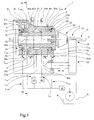
- la figure 3 est une coupe partielle selon la ligne III-III de la figure 1.
On voit aux figures 1 et 2 une unité de broche selon l'invention, désignée par la
référence numérique générale 1. L'unité de broche 1 comprend un bâti 2 comprenant
un alésage 2a dans lequel est monté à rotation un arbre 4 par l'intermédiaire de
quatre paliers 6, 8, 10 et 12. L'arbre 4 est supporté radialement par deux paliers
radiaux 6, 8 et est supporté axialement par deux paliers axiaux 10,12. Les paliers
radiaux et axiaux 6, 8, 10, 12 sont des paliers hydrostatiques bien connus des
hommes du métier, bien que dans selon une variante de réalisation de l'invention les
paliers axiaux puissent être des paliers du type à roulement à billes, les paliers
radiaux restant quant à eux des paliers hydrostatiques
L'arbre 4 comprend à une première extrémité, dite extrémité avant, des
moyens de serrage 14 pour serrer une pièce à usiner 16. Les moyens de serrage
comprennent typiquement une pince de serrage ou un mandrin de serrage classique
à commande manuelle, hydraulique ou à air comprimé.
L'unité de broche 1 comprend en outre un palier supplémentaire 18 disposé
au-delà des moyens de serrage 14 et apte à guider sans jeu la pièce à usiner 16.
Typiquement le palier 18 comprend une gorge 20 en forme de V, le fond de la gorge
s'étendant parallèlement à l'axe de rotation de l'arbre 4. La pièce à usiner 16 repose
ainsi sur les flancs intérieurs de la gorge 20. En outre, la gorge 20 est associée à un
doigt 22 qui applique une pression sur la pièce à usiner 16 afin de la maintenir contre
lesdits flancs et ainsi assure un guidage sans jeu de la pièce 16. Dans l'exemple
illustré, le palier 18 est solidaire d'un support 24 qui peut coulisser dans le bâti 2 de
l'unité de broche 1, le long d'une direction parallèle à l'axe de rotation A-A' de l'arbre
4.
A la figure 1, on voit que l'extrémité avant de l'arbre 4 comporte un épaulement
26 ayant une face arrière 26a. L'épaulement 26 permet à l'arbre 4 de s'appuyer, par
l'intermédiaire la face arrière 26a, dans un dégagement 28 ménagé dans la partie
avant du bâti 2. Le fond du dégagement comprend une rainure annulaire 30 en
communication avec une source de fluide S par l'intermédiaire d'une ligne L30
comprenant un limiteur de débit 30a et un limiteur de pression 32. A cet effet, un
canal C30 relie la rainure 30 à un orifice (non représenté) ménagé à la surface
extérieure du bâti et relié au limiteur de débit 30a. La rainure annulaire 30 forme ainsi
avec la face arrière 26a de l'épaulement 26 le palier hydrostatique axial 12.
Typiquement la source de fluide comprend un réservoir R associé à une pompe P qui
alimente le limiteur de pression 32.
L'arbre 4 comporte à son extrémité opposée, dite extrémité arrière, une poulie
34 comportant un moyeu 34a, un flasque 34b et une surface périphérique 34c. Le
moyeu 34a de la poulie est monté solidaire en rotation sur l'extrémité arrière de l'arbre
4. La surface périphérique 34c coopère avec une courroie d'entraínement 36 reliée à
des moyens moteurs (non représentés) pour l'entraínement en rotation de l'arbre 4.
En outre, la partie arrière du bâti 2 comprend une rainure annulaire 38 également en
communication avec la source de fluide S par l'intermédiaire d'une ligne L38
comprenant un limiteur de débit 38a et le limiteur de pression 32. A cet effet, un canal
C38 relie la rainure 38 à un orifice (non représenté) ménagé à la surface extérieure du
bâti et relié au limiteur de débit 38a. Une face du flasque 34b de la poulie 34 s'appuie
en regard de la rainure 38 pour former le palier hydrostatique axial 10.
Nous allons maintenant décrire la structure des paliers radiaux 6 et 8 en liaison
avec les figures 1 et 2. Comme les paliers radiaux 6 et 8 présentent une structure
sensiblement identique, seul le palier 6 a été représenté en coupe à la figure 2. Ainsi,
les références numériques associées respectivement aux lettres a, b, c et d désignent
ci-après des éléments ayant une structure et une fonction sensiblement identiques,
même s'ils n'apparaissent pas sur les figures, les références 8a à 8d correspondent
donc aux références 6a à 6d.
En se référant notamment aux figures 1 et 2 on voit que les paliers 6 et 8
comprennent chacun quatre chambres 6a, 6b, 6c, 6d, 8a, 8b, 8c et 8d ménagées
dans l'alésage 2a. Dans chaque palier, les chambres 6a-6d et 8a-8d sont décalées
les unes par rapport aux autres de 90° autour de l'axe de rotation de l'arbre 4. Les
chambres 6a-6d du palier 6 sont chacune en communication avec la source de fluide
S par l'intermédiaire d'une ligne L6 comprenant un limiteur de débit associé 40a, 40b,
40c et 40d, un limiteur de pression 42 et le limiteur de pression 32. Il en va de même
pour les chambres 8a-8d du palier 8 qui sont chacune en communication avec la
source de fluide S par l'intermédiaire d'une ligne L8 comprenant un limiteur de débit
associé 44a, 44b, 44c et 44d, un limiteur de pression 46 et le limiteur de pression 32.
Des canaux C40a-d et C44a-d ménagés dans le corps du bâti 2 relient respectivement les
chambres 6a-d et 8a-d à des orifices 48a-d et 50a-d ménagés à la surface extérieure
du bâti et reliés respectivement aux limiteurs de débit 40a-d et 44a-d.
Comme cela est visible de la figure 1, le bâti 2 comprend en outre une
chambre de collecte 51 ménagée dans l'alésage 2a relié à la source de fluide par
l'intermédiaire d'une ligne de retour LR. A cet effet, un canal CR relie la chambre 51 à
un orifice 51a ménagé à la surface extérieure du bâti et relié via la ligne de retour au
réservoir R de la source de fluide F.
Les lignes L6, L8, L30, L38 sont branchées en parallèle sur la pompe P et
forment avec la ligne LR un circuit hydraulique fermé qui alimente les quatre paliers
hydrostatiques 6, 8, 10 et 12 avec des pressions et des débits qui peuvent être
ajustés séparément pour chacun des paliers.
Les paliers axiaux 10 et12 sont alimentés classiquement en fluide à une
pression PA déterminée par le limiteur de pression 32 et les limiteurs de débit 30a et
38a respectivement, la pression et les débits étant choisis de manière à obtenir une
rigidité axiale élevée des paliers 10 et 12. En revanche, les paliers radiaux 6 et 8 sont
alimentés avec des pressions PR6 et PR8 très différentes. En effet, les pressions PR6 et
PR8 en sortie des limiteurs de pression respectifs 42 et 46 et les débits en sortie des
limiteurs de débit 40a-d et 44a-d sont agencés pour que le palier radial 8 permette à
l'arbre 4 un mouvement radial limité dans un plan perpendiculaire à l'axe de rotation
A-A', l'amplitude de ce mouvement radial étant supérieure à celle du mouvement
radial de l'arbre 4 permis par le palier radial 6. De préférence, la pression PR6 et les
débits en sortie des limiteurs de débit respectifs 40a-d sont ajustés pour que
l'amplitude du mouvement radial de l'arbre 4 au niveau de palier radial 6 est
sensiblement nulle. D'autre part, la pression PR8 et les débit en sortie des limiteurs de
débit 44a-d respectivement sont ajustés pour que l'amplitude du mouvement radial de
l'arbre 4 au niveau du palier radial 8 oscille au maximum entre ± 0,03 mm autour
d'une position médiane, et de préférence entre ± 0,01 mm.
Pour fixer les idées, par amplitude sensiblement nulle on entend une amplitude
de quelques micromètres. A cet effet, la pression P6 présente dans le palier radial 6
est supérieure à la pression P8 présente dans le palier radial 8. Typiquement, le
rapport des pressions P6/ P8 varie entre 1 et 20 et sera de préférence le plus grand
possible. A titre d'exemple, une pression P6 de 50 bars et une pression P8 de 5 bars
ont donné des résultats satisfaisants.
On s'aperçoit que l'on peut donner au montage classiquement rigide de l'arbre
4 dans le bâti 2 une certaine flexibilité en permettant un mouvement d'amplitude
limitée dans la zone du palier radial 8, c'est-à-dire dans la zone du palier radial non
rigide. Dans un montage à rotation à trois paliers radiaux, à savoir deux paliers
d'extrémité 6, 18 et un palier intermédiaire 8, comme cela est représenté à la figure 1,
le guidage non rigide ou flottant au niveau du palier intermédiaire 8 sert à réduire,
voire éliminer, l'effet d'un éventuel défaut de concentricité entre l'axe de rotation de
l'arbre, l'axe des moyens de serrage et l'axe de la pièce à usiner dans la mesure où
un certain mouvement dans le plan perpendiculaire à l'axe de rotation de l'arbre est
autorisé, étant entendu qu'aucun mouvement dans ce plan n'est autorisé par les
paliers radiaux d'extrémité qui sont maintenus rigides.
On comprendra que diverses modifications et/ou améliorations évidentes pour
l'homme de métier peuvent être apportées au mode de réalisation décrit dans la
présente description sans sortir du cadre de la présente invention définie par les
revendications annexées. On pourra notamment prévoir d'utiliser des paliers à air à la
place des paliers hydrostatiques.
Claims (6)
- Unité de broche comprenant un bâti, un arbre muni à une de ses extrémités de moyens de serrage pour serrer une pièce à usiner, ledit arbre étant monté à rotation dans ledit bâti et supporté radialement par l'intermédiaire de premier et deuxième paliers radiaux, ledit arbre étant entraíné à rotation par des moyens moteurs, ladite unité comprenant en outre un troisième palier disposé au-delà desdits moyens de serrage et apte à guider ladite pièce à usiner, caractérisée en ce que les premier et deuxième paliers radiaux sont des paliers hydrostatiques et en ce que le deuxième palier radial, situé du côté du troisième palier, est agencé pour permettre audit arbre, dans la région dudit deuxième palier, un mouvement radial limité dans un plan perpendiculaire à l'axe de rotation de l'arbre, l'amplitude maximale dudit mouvement radial étant supérieure à celle de tout mouvement radial de l'arbre pouvant être permis par ledit premier palier radial.
- Unité de broche selon la revendication 1, caractérisée en ce que l'amplitude dudit mouvement radial au niveau du premier palier est sensiblement nulle et en ce l'amplitude dudit mouvement radial au niveau du deuxième palier est au maximum de l'ordre de ± 0.03 mm autour de la position médiane et de préférence de l'ordre de ± 0,01 mm .
- Unité de broche selon la revendication 1 ou 2, caractérisée en ce que les premier et deuxième paliers radiaux sont sensiblement identiques et en ce que la pression de fluide présente dans le premier palier radial est supérieure à celle présente dans le deuxième palier radial.
- Unité de broche selon la revendication 1 ou 2, caractérisée en ce que ledit arbre est également supporté axialement par une paire de paliers hydrostatiques.
- Unité de broche selon l'une quelconque des revendications précédentes, caractérisée en ce que les premier et deuxième paliers radiaux comprennent respectivement des premières et deuxièmes chambres de pression reliées respectivement à un circuit d'alimentation de fluide et en ce que le circuit d'alimentation de fluide comprend des moyens d'ajustement de la pression dans lesdites première et deuxièmes chambres respectivement.
- Unité de broche selon l'une quelconque des revendications précédentes, caractérisée en ce que le troisième palier assure un guidage sans jeu de la pièce à usiner.
Priority Applications (3)
| Application Number | Priority Date | Filing Date | Title |
|---|---|---|---|
| EP02079754A EP1419852A1 (fr) | 2002-11-12 | 2002-11-12 | Unité de broche |
| AU2003283319A AU2003283319A1 (en) | 2002-11-12 | 2003-10-30 | Spindle unit |
| PCT/EP2003/012034 WO2004043646A1 (fr) | 2002-11-12 | 2003-10-30 | Unite de broche |
Applications Claiming Priority (1)
| Application Number | Priority Date | Filing Date | Title |
|---|---|---|---|
| EP02079754A EP1419852A1 (fr) | 2002-11-12 | 2002-11-12 | Unité de broche |
Publications (1)
| Publication Number | Publication Date |
|---|---|
| EP1419852A1 true EP1419852A1 (fr) | 2004-05-19 |
Family
ID=32116306
Family Applications (1)
| Application Number | Title | Priority Date | Filing Date |
|---|---|---|---|
| EP02079754A Withdrawn EP1419852A1 (fr) | 2002-11-12 | 2002-11-12 | Unité de broche |
Country Status (3)
| Country | Link |
|---|---|
| EP (1) | EP1419852A1 (fr) |
| AU (1) | AU2003283319A1 (fr) |
| WO (1) | WO2004043646A1 (fr) |
Cited By (7)
| Publication number | Priority date | Publication date | Assignee | Title |
|---|---|---|---|---|
| CN101774156A (zh) * | 2010-03-03 | 2010-07-14 | 天津市中马骏腾精密机械制造有限公司 | 高精度磨床 |
| CN103846745A (zh) * | 2012-11-30 | 2014-06-11 | 昆山允可精密工业技术有限公司 | 一种刀具磨床用精密二维运动平台 |
| CN104400569A (zh) * | 2014-10-27 | 2015-03-11 | 重庆建设工业(集团)有限责任公司 | 班用枪族刺刀开刃夹具 |
| CN104440420A (zh) * | 2013-09-18 | 2015-03-25 | 深圳市金洲精工科技股份有限公司 | 一种钻径磨削机床的定位机构 |
| DE102013111599A1 (de) | 2013-10-21 | 2015-08-06 | Feinmechanik Michael Deckel Gmbh & Co Kg | Spindel einer Werkzeugschleifmaschine |
| CN105538052A (zh) * | 2016-02-24 | 2016-05-04 | 深圳市金洲精工科技股份有限公司 | 旋转切削工具磨削及夹持装置 |
| CN109759934A (zh) * | 2019-01-18 | 2019-05-17 | 宁波市江北甬丰轴承有限公司 | 一种轴承加工用打磨设备 |
Families Citing this family (3)
| Publication number | Priority date | Publication date | Assignee | Title |
|---|---|---|---|---|
| DE102005007038B4 (de) | 2005-02-15 | 2009-10-15 | Alfred H. Schütte GmbH & Co. KG | Werkstückspindelstock |
| CN103846746A (zh) * | 2012-11-30 | 2014-06-11 | 昆山允可精密工业技术有限公司 | 一种刀具磨床用精密旋转轴 |
| CN103481132B (zh) * | 2013-09-30 | 2016-06-15 | 平湖市山特螺纹工具有限公司 | 丝锥铲磨机的磨头座 |
Citations (3)
| Publication number | Priority date | Publication date | Assignee | Title |
|---|---|---|---|---|
| US3742653A (en) * | 1970-08-05 | 1973-07-03 | Toyoda Machine Works Ltd | Control devices for the radial displacement of shafts |
| DE8915435U1 (de) * | 1989-03-22 | 1990-06-07 | J. E. Reinecker Maschinenbau GmbH & Co KG, 7900 Ulm | Vorrichtung zur Bearbeitung eines etwa stabförmigen rotierenden Werkstücks |
| US6375542B1 (en) * | 1999-08-23 | 2002-04-23 | Moore Tool Company Incorporated | Hydrostatic spindle unit with automatic self centering of the workpiece |
-
2002
- 2002-11-12 EP EP02079754A patent/EP1419852A1/fr not_active Withdrawn
-
2003
- 2003-10-30 AU AU2003283319A patent/AU2003283319A1/en not_active Abandoned
- 2003-10-30 WO PCT/EP2003/012034 patent/WO2004043646A1/fr not_active Application Discontinuation
Patent Citations (3)
| Publication number | Priority date | Publication date | Assignee | Title |
|---|---|---|---|---|
| US3742653A (en) * | 1970-08-05 | 1973-07-03 | Toyoda Machine Works Ltd | Control devices for the radial displacement of shafts |
| DE8915435U1 (de) * | 1989-03-22 | 1990-06-07 | J. E. Reinecker Maschinenbau GmbH & Co KG, 7900 Ulm | Vorrichtung zur Bearbeitung eines etwa stabförmigen rotierenden Werkstücks |
| US6375542B1 (en) * | 1999-08-23 | 2002-04-23 | Moore Tool Company Incorporated | Hydrostatic spindle unit with automatic self centering of the workpiece |
Cited By (9)
| Publication number | Priority date | Publication date | Assignee | Title |
|---|---|---|---|---|
| CN101774156A (zh) * | 2010-03-03 | 2010-07-14 | 天津市中马骏腾精密机械制造有限公司 | 高精度磨床 |
| CN103846745A (zh) * | 2012-11-30 | 2014-06-11 | 昆山允可精密工业技术有限公司 | 一种刀具磨床用精密二维运动平台 |
| CN104440420A (zh) * | 2013-09-18 | 2015-03-25 | 深圳市金洲精工科技股份有限公司 | 一种钻径磨削机床的定位机构 |
| CN104440420B (zh) * | 2013-09-18 | 2017-11-14 | 深圳市金洲精工科技股份有限公司 | 一种钻径磨削机床的定位机构 |
| DE102013111599A1 (de) | 2013-10-21 | 2015-08-06 | Feinmechanik Michael Deckel Gmbh & Co Kg | Spindel einer Werkzeugschleifmaschine |
| CN104400569A (zh) * | 2014-10-27 | 2015-03-11 | 重庆建设工业(集团)有限责任公司 | 班用枪族刺刀开刃夹具 |
| CN104400569B (zh) * | 2014-10-27 | 2016-09-07 | 重庆建设工业(集团)有限责任公司 | 班用枪族刺刀开刃夹具 |
| CN105538052A (zh) * | 2016-02-24 | 2016-05-04 | 深圳市金洲精工科技股份有限公司 | 旋转切削工具磨削及夹持装置 |
| CN109759934A (zh) * | 2019-01-18 | 2019-05-17 | 宁波市江北甬丰轴承有限公司 | 一种轴承加工用打磨设备 |
Also Published As
| Publication number | Publication date |
|---|---|
| WO2004043646A1 (fr) | 2004-05-27 |
| AU2003283319A1 (en) | 2004-06-03 |
Similar Documents
| Publication | Publication Date | Title |
|---|---|---|
| FR2556254A1 (fr) | Ensemble porte-outil | |
| EP1816374B1 (fr) | Procédé de fabrication d'un réducteur, réducteur et robot incorporant un tel réducteur | |
| FR2542652A1 (fr) | Dispositif d'accouplement pour outillages modulaires | |
| EP1419852A1 (fr) | Unité de broche | |
| EP2168703A1 (fr) | Porte-outil à réglage axial | |
| EP1317329B1 (fr) | Tete a aleser | |
| EP0958105B1 (fr) | Dispositif d'usinage par enlevement de copeaux, a bloc massif et colonne coulissante, et machine incorporant ce dispositif | |
| FR2490132A1 (fr) | ||
| EP0655296B1 (fr) | Dispositif porte-outil, notamment tête de fraisage, à porte-broche orientable | |
| EP0806264A1 (fr) | Machine-outil à broche excentrable | |
| FR3027541A1 (fr) | Dispositif d'usinage vibratoire ameliore | |
| FR2612438A1 (fr) | Machine-outil, notamment perceuse ou taraudeuse | |
| EP3003616B1 (fr) | Dispositif d'usinage vibratoire | |
| FR2466296A1 (fr) | Nez de broche pour machines-outils | |
| EP0074452B1 (fr) | Dispositif d'accouplement pour têtes de fraisage | |
| EP3837074B1 (fr) | Dispositif de percage orbital | |
| FR2464793A1 (fr) | Mecanisme d'ejection d'outil et machine equipes d'un tel mecanisme | |
| FR2704789A1 (fr) | Tête révolver multibroche pour machine-outil. | |
| EP0235019A1 (fr) | Ensemble monobloc broche rotative porte-outil et moteur électrique | |
| EP4084922B1 (fr) | Electro-broche a avance integree avec changement automatique de porte-outil | |
| FR2590819A1 (fr) | Dispositif de reglage axial d'outils de machine outils | |
| FR2521049A1 (fr) | Dispositif permettant d'agir sur la position relative de deux elements accouples d'une machine-outil | |
| FR2473930A2 (fr) | Outillage pour la reparation, en particulier pour rodage d'un siege de robinet | |
| FR2743743A1 (fr) | Instrument a main pour l'usinage de pieces, notamment de pieces mecaniques | |
| FR2801824A1 (fr) | Outil de coupe |
Legal Events
| Date | Code | Title | Description |
|---|---|---|---|
| PUAI | Public reference made under article 153(3) epc to a published international application that has entered the european phase |
Free format text: ORIGINAL CODE: 0009012 |
|
| AK | Designated contracting states |
Kind code of ref document: A1 Designated state(s): AT BE BG CH CY CZ DE DK EE ES FI FR GB GR IE IT LI LU MC NL PT SE SK TR |
|
| AX | Request for extension of the european patent |
Extension state: AL LT LV MK RO SI |
|
| AKX | Designation fees paid | ||
| REG | Reference to a national code |
Ref country code: DE Ref legal event code: 8566 |
|
| STAA | Information on the status of an ep patent application or granted ep patent |
Free format text: STATUS: THE APPLICATION IS DEEMED TO BE WITHDRAWN |
|
| 18D | Application deemed to be withdrawn |
Effective date: 20041120 |