EP1419852A1 - Spindeleinheit - Google Patents
Spindeleinheit Download PDFInfo
- Publication number
- EP1419852A1 EP1419852A1 EP02079754A EP02079754A EP1419852A1 EP 1419852 A1 EP1419852 A1 EP 1419852A1 EP 02079754 A EP02079754 A EP 02079754A EP 02079754 A EP02079754 A EP 02079754A EP 1419852 A1 EP1419852 A1 EP 1419852A1
- Authority
- EP
- European Patent Office
- Prior art keywords
- bearing
- shaft
- radial
- bearings
- spindle unit
- Prior art date
- Legal status (The legal status is an assumption and is not a legal conclusion. Google has not performed a legal analysis and makes no representation as to the accuracy of the status listed.)
- Withdrawn
Links
Images


Classifications
-
- B—PERFORMING OPERATIONS; TRANSPORTING
- B23—MACHINE TOOLS; METAL-WORKING NOT OTHERWISE PROVIDED FOR
- B23Q—DETAILS, COMPONENTS, OR ACCESSORIES FOR MACHINE TOOLS, e.g. ARRANGEMENTS FOR COPYING OR CONTROLLING; MACHINE TOOLS IN GENERAL CHARACTERISED BY THE CONSTRUCTION OF PARTICULAR DETAILS OR COMPONENTS; COMBINATIONS OR ASSOCIATIONS OF METAL-WORKING MACHINES, NOT DIRECTED TO A PARTICULAR RESULT
- B23Q3/00—Devices holding, supporting, or positioning work or tools, of a kind normally removable from the machine
- B23Q3/18—Devices holding, supporting, or positioning work or tools, of a kind normally removable from the machine for positioning only
- B23Q3/183—Centering devices
-
- B—PERFORMING OPERATIONS; TRANSPORTING
- B23—MACHINE TOOLS; METAL-WORKING NOT OTHERWISE PROVIDED FOR
- B23Q—DETAILS, COMPONENTS, OR ACCESSORIES FOR MACHINE TOOLS, e.g. ARRANGEMENTS FOR COPYING OR CONTROLLING; MACHINE TOOLS IN GENERAL CHARACTERISED BY THE CONSTRUCTION OF PARTICULAR DETAILS OR COMPONENTS; COMBINATIONS OR ASSOCIATIONS OF METAL-WORKING MACHINES, NOT DIRECTED TO A PARTICULAR RESULT
- B23Q1/00—Members which are comprised in the general build-up of a form of machine, particularly relatively large fixed members
- B23Q1/25—Movable or adjustable work or tool supports
- B23Q1/26—Movable or adjustable work or tool supports characterised by constructional features relating to the co-operation of relatively movable members; Means for preventing relative movement of such members
- B23Q1/38—Movable or adjustable work or tool supports characterised by constructional features relating to the co-operation of relatively movable members; Means for preventing relative movement of such members using fluid bearings or fluid cushion supports
- B23Q1/385—Movable or adjustable work or tool supports characterised by constructional features relating to the co-operation of relatively movable members; Means for preventing relative movement of such members using fluid bearings or fluid cushion supports in which the thickness of the fluid-layer is adjustable
-
- B—PERFORMING OPERATIONS; TRANSPORTING
- B23—MACHINE TOOLS; METAL-WORKING NOT OTHERWISE PROVIDED FOR
- B23Q—DETAILS, COMPONENTS, OR ACCESSORIES FOR MACHINE TOOLS, e.g. ARRANGEMENTS FOR COPYING OR CONTROLLING; MACHINE TOOLS IN GENERAL CHARACTERISED BY THE CONSTRUCTION OF PARTICULAR DETAILS OR COMPONENTS; COMBINATIONS OR ASSOCIATIONS OF METAL-WORKING MACHINES, NOT DIRECTED TO A PARTICULAR RESULT
- B23Q1/00—Members which are comprised in the general build-up of a form of machine, particularly relatively large fixed members
- B23Q1/70—Stationary or movable members for carrying working-spindles for attachment of tools or work
-
- B—PERFORMING OPERATIONS; TRANSPORTING
- B24—GRINDING; POLISHING
- B24B—MACHINES, DEVICES, OR PROCESSES FOR GRINDING OR POLISHING; DRESSING OR CONDITIONING OF ABRADING SURFACES; FEEDING OF GRINDING, POLISHING, OR LAPPING AGENTS
- B24B3/00—Sharpening cutting edges, e.g. of tools; Accessories therefor, e.g. for holding the tools
- B24B3/24—Sharpening cutting edges, e.g. of tools; Accessories therefor, e.g. for holding the tools of drills
- B24B3/247—Supports for drills
-
- B—PERFORMING OPERATIONS; TRANSPORTING
- B24—GRINDING; POLISHING
- B24B—MACHINES, DEVICES, OR PROCESSES FOR GRINDING OR POLISHING; DRESSING OR CONDITIONING OF ABRADING SURFACES; FEEDING OF GRINDING, POLISHING, OR LAPPING AGENTS
- B24B41/00—Component parts such as frames, beds, carriages, headstocks
- B24B41/04—Headstocks; Working-spindles; Features relating thereto
-
- B—PERFORMING OPERATIONS; TRANSPORTING
- B24—GRINDING; POLISHING
- B24B—MACHINES, DEVICES, OR PROCESSES FOR GRINDING OR POLISHING; DRESSING OR CONDITIONING OF ABRADING SURFACES; FEEDING OF GRINDING, POLISHING, OR LAPPING AGENTS
- B24B41/00—Component parts such as frames, beds, carriages, headstocks
- B24B41/06—Work supports, e.g. adjustable steadies
- B24B41/066—Work supports, e.g. adjustable steadies adapted for supporting work in the form of tools, e.g. drills
Definitions
- the present invention generally relates to the field of machine tools and more particularly a spindle unit comprising a rigid guide bearing a workpiece, used in particular for grinding cutting tools such than drills, strawberries or the like.
- Spindle units fitted to machine tools generally include a shaft fitted at one end with a clamp or jaws intended to clamp a workpiece.
- the shaft is rotatably mounted in a frame by means of two pairs of rolling bearings to support respectively the axial and radial forces applied to the shaft during the machining of said part.
- a most commonly encountered problems when using these spindle units lies in the difficulty of controlling the concentricity of the workpiece clamped in the clamp relative to the axis of rotation of the shaft, which in particular causes a orbital movement of the workpiece around said axis of rotation. This difficulty can be explained in particular by the inherent defects in the concentricity of the pliers hole relative to the axis of rotation of the spindle.
- clamping systems such pliers, high precision, whose concentricity defects are included in a range of 3 to 5 micrometers, solves the problem when the tolerances of the parts to be produced are of the same order. There is however a problem when the dimensional accuracy of the parts to be produced is less than the range supra.
- an additional rigid guide bearing supporting the part to machine and positioned beyond the gripper at a determined distance therefrom typically includes a V-shaped piece associated with a clamping finger which maintains the workpiece at the bottom of the V and thus considerably limits the orbital movement of the workpiece in the cantilevered part of the latter.
- the additional bearing prevents orbital movement near the free end of the workpiece, the clamp and / or the part of the workpiece located in the area between the clamp and the additional bearing must have a certain flexibility to allow this movement in this area. This solution cannot be therefore be considered only for workpieces of small dimensions, typically of the order of 3 mm in diameter, with which such deformation can be taken back by the parts.
- the main object of the present invention is therefore to remedy the drawbacks of the aforementioned prior art by providing a spindle unit which is simple and which allows machining of workpieces of any size with a lack of minimal concentricity.
- the invention also aims to provide such a spindle unit in allowing its operating conditions to be easily adapted to the dimensions and tolerances of the workpieces.
- the invention also aims to provide such a spindle unit which has a low manufacturing cost.
- the invention relates to a spindle unit comprising a frame, a shaft provided at one end with clamping means for clamping a workpiece machining, said shaft being rotatably mounted in said frame and supported radially by first and second radial bearings, said shaft being driven to rotation by motor means, said unit further comprising a third bearing disposed beyond said clamping means and capable of guiding said workpiece, characterized in that the first and second radial bearings are bearings hydrostatic and in that the second radial bearing situated on the side of the third bearing, is arranged to allow said shaft, in the region of said second bearing, a radial movement limited in a plane perpendicular to the axis of rotation of the shaft, the maximum amplitude of said radial movement being greater than that of any radial movement of the shaft which can be allowed by said first radial bearing.
- this spindle unit is the simplicity of the means used to perform machining with concentricity defects minimum. Indeed, hydrostatic bearing systems can be used in which it suffices to adjust the pressures appropriately to allow the desired limited radial movement in the plane perpendicular to the axis of rotation of the tree at the second level.
- the amplitude of said radial movement at the level of the first bearing is substantially zero and the amplitude of said radial movement at the level of the second bearing is at most of the order of ⁇ 0.03 mm around the middle position and preferably of the order of ⁇ 0.01 mm.
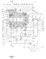
- FIGS. 1 and 2 show a spindle unit according to the invention, designated by the general numerical reference 1.
- the spindle unit 1 comprises a frame 2 comprising a bore 2a in which a shaft 4 is rotatably mounted by means of four bearings 6, 8, 10 and 12.
- the shaft 4 is supported radially by two bearings radial 6, 8 and is supported axially by two axial bearings 10,12.
- the bearings radial and axial 6, 8, 10, 12 are hydrostatic bearings well known to skilled in the art, although in an alternative embodiment of the invention the axial bearings may be bearings of the ball bearing type, the bearings radials remaining hydrostatic bearings
- the shaft 4 comprises at a first end, called the front end, clamping means 14 for clamping a workpiece 16.
- clamping means typically include a collet or a conventional collet with manual, hydraulic or compressed air control.
- the spindle unit 1 further comprises an additional bearing 18 arranged beyond the clamping means 14 and capable of guiding the workpiece 16 without play.
- the bearing 18 comprises a V-shaped groove 20, the bottom of the groove extending parallel to the axis of rotation of the shaft 4. The workpiece 16 rests thus on the inner flanks of the groove 20.
- the groove 20 is associated with a finger 22 which applies pressure to the workpiece 16 in order to keep it against said sides and thus ensures a play-free guide of the part 16.
- the bearing 18 is integral with a support 24 which can slide in the frame 2 of the spindle unit 1, along a direction parallel to the axis of rotation A-A 'of the shaft 4.
- the front end of the shaft 4 has a shoulder 26 having a rear face 26a.
- the shoulder 26 allows the shaft 4 to bear, via the rear face 26a, in a recess 28 formed in the front part of the frame 2.
- the bottom of the recess comprises an annular groove 30 in communication with a fluid source S via a line L 30 comprising a flow limiter 30a and a pressure limiter 32.
- a channel C 30 connects the groove 30 to an orifice (not shown) formed on the surface exterior of the frame and connected to the flow limiter 30a.
- the annular groove 30 thus forms with the rear face 26a of the shoulder 26 the axial hydrostatic bearing 12.
- the source of fluid comprises a reservoir R associated with a pump P which supplies the pressure relief valve 32.
- the shaft 4 has at its opposite end, called the rear end, a pulley 34 comprising a hub 34a, a flange 34b and a peripheral surface 34c.
- the hub 34a of the pulley is rotatably mounted on the rear end of the shaft 4.
- the peripheral surface 34c cooperates with a drive belt 36 connected to motor means (not shown) for the rotational drive of the shaft 4.
- the rear part of the frame 2 comprises an annular groove 38 also in communication with the fluid source S via a line L 38 comprising a flow limiter 38a and the pressure limiter 32
- a channel C 38 connects the groove 38 to an orifice (not shown) formed on the external surface of the frame and connected to the flow limiter 38a.
- One face of the flange 34b of the pulley 34 bears opposite the groove 38 to form the axial hydrostatic bearing 10.
- the bearings 6 and 8 each include four chambers 6a, 6b, 6c, 6d, 8a, 8b, 8c and 8d formed in the bore 2a.
- the chambers 6a-6d and 8a-8d are offset relative to each other by 90 ° around the axis of rotation of the shaft 4.
- the chambers 6a-6d of the bearing 6 are each in communication with the fluid source S via a line L 6 comprising an associated flow limiter 40a, 40b, 40c and 40d, a pressure limiter 42 and the pressure limiter 32.
- chambers 8a -8d of the bearing 8 which are each in communication with the fluid source S via a line L 8 comprising an associated flow limiter 44a, 44b, 44c and 44d, a pressure limiter 46 and the pressure limiter 32.
- Channels C 40a-d and C 44a-d formed in the body of the frame 2 connect the chambers 6a-d and 8a-d respectively to orifices 48a-d and 50a-d formed on the outer surface of the frame and connected flow restrictors 40a-d and 44a-d respectively.
- the frame 2 further comprises a collection chamber 51 formed in the bore 2a connected to the source of fluid via a return line L R.
- a channel C R connects the chamber 51 to an orifice 51a formed on the exterior surface of the frame and connected via the return line to the reservoir R of the source of fluid F.
- the lines L6, L8, L30, L38 are connected in parallel to the pump P and form with the line L R a closed hydraulic circuit which supplies the four hydrostatic bearings 6, 8, 10 and 12 with pressures and flow rates which can be adjusted separately for each level.
- the axial bearings 10 and 12 are conventionally supplied with fluid at a pressure P A determined by the pressure limiter 32 and the flow limiters 30a and 38a respectively, the pressure and the flow rates being chosen so as to obtain a high axial rigidity of the bearings 10 and 12.
- the radial bearings 6 and 8 are supplied with very different pressures P R6 and P R8 .
- the pressures P R6 and P R8 at the outlet of the respective pressure relief valves 42 and 46 and the flows at the outlet of the flow restrictors 40a-d and 44a-d are arranged so that the radial bearing 8 allows the shaft 4 a radial movement limited in a plane perpendicular to the axis of rotation A-A ', the amplitude of this radial movement being greater than that of the radial movement of the shaft 4 allowed by the radial bearing 6.
- the pressure P R6 and the flows at the output of the respective flow limiters 40a-d are adjusted so that the amplitude of the radial movement of the shaft 4 at the level of the radial bearing 6 is substantially zero.
- the pressure P R8 and the flows at the output of the flow restrictors 44a-d respectively are adjusted so that the amplitude of the radial movement of the shaft 4 at the level of the radial bearing 8 oscillates at most between ⁇ 0, 03 mm around a middle position, and preferably between ⁇ 0.01 mm.
- substantially zero amplitude is meant an amplitude of a few micrometers.
- the pressure P 6 present in the radial bearing 6 is greater than the pressure P 8 present in the radial bearing 8.
- the ratio of pressures P 6 / P 8 varies between 1 and 20 and will preferably be the most great possible.
- a pressure P 6 of 50 bars and a pressure P 8 of 5 bars have given satisfactory results.
- non-rigid or floating guidance at the intermediate bearing 8 serves to reduce, or even eliminate, the effect of a possible lack of concentricity between the axis of rotation of the shaft, the axis of the clamping means and the axis of the workpiece as far as some movement in the plane perpendicular to the axis of rotation of the shaft is authorized, it being understood that no movement in this plane is authorized by the radial end bearings which are kept rigid.
Priority Applications (3)
| Application Number | Priority Date | Filing Date | Title |
|---|---|---|---|
| EP02079754A EP1419852A1 (de) | 2002-11-12 | 2002-11-12 | Spindeleinheit |
| AU2003283319A AU2003283319A1 (en) | 2002-11-12 | 2003-10-30 | Spindle unit |
| PCT/EP2003/012034 WO2004043646A1 (fr) | 2002-11-12 | 2003-10-30 | Unite de broche |
Applications Claiming Priority (1)
| Application Number | Priority Date | Filing Date | Title |
|---|---|---|---|
| EP02079754A EP1419852A1 (de) | 2002-11-12 | 2002-11-12 | Spindeleinheit |
Publications (1)
| Publication Number | Publication Date |
|---|---|
| EP1419852A1 true EP1419852A1 (de) | 2004-05-19 |
Family
ID=32116306
Family Applications (1)
| Application Number | Title | Priority Date | Filing Date |
|---|---|---|---|
| EP02079754A Withdrawn EP1419852A1 (de) | 2002-11-12 | 2002-11-12 | Spindeleinheit |
Country Status (3)
| Country | Link |
|---|---|
| EP (1) | EP1419852A1 (de) |
| AU (1) | AU2003283319A1 (de) |
| WO (1) | WO2004043646A1 (de) |
Cited By (7)
| Publication number | Priority date | Publication date | Assignee | Title |
|---|---|---|---|---|
| CN101774156A (zh) * | 2010-03-03 | 2010-07-14 | 天津市中马骏腾精密机械制造有限公司 | 高精度磨床 |
| CN103846745A (zh) * | 2012-11-30 | 2014-06-11 | 昆山允可精密工业技术有限公司 | 一种刀具磨床用精密二维运动平台 |
| CN104400569A (zh) * | 2014-10-27 | 2015-03-11 | 重庆建设工业(集团)有限责任公司 | 班用枪族刺刀开刃夹具 |
| CN104440420A (zh) * | 2013-09-18 | 2015-03-25 | 深圳市金洲精工科技股份有限公司 | 一种钻径磨削机床的定位机构 |
| DE102013111599A1 (de) | 2013-10-21 | 2015-08-06 | Feinmechanik Michael Deckel Gmbh & Co Kg | Spindel einer Werkzeugschleifmaschine |
| CN105538052A (zh) * | 2016-02-24 | 2016-05-04 | 深圳市金洲精工科技股份有限公司 | 旋转切削工具磨削及夹持装置 |
| CN109759934A (zh) * | 2019-01-18 | 2019-05-17 | 宁波市江北甬丰轴承有限公司 | 一种轴承加工用打磨设备 |
Families Citing this family (3)
| Publication number | Priority date | Publication date | Assignee | Title |
|---|---|---|---|---|
| DE102005007038B4 (de) | 2005-02-15 | 2009-10-15 | Alfred H. Schütte GmbH & Co. KG | Werkstückspindelstock |
| CN103846746A (zh) * | 2012-11-30 | 2014-06-11 | 昆山允可精密工业技术有限公司 | 一种刀具磨床用精密旋转轴 |
| CN103481132B (zh) * | 2013-09-30 | 2016-06-15 | 平湖市山特螺纹工具有限公司 | 丝锥铲磨机的磨头座 |
Citations (3)
| Publication number | Priority date | Publication date | Assignee | Title |
|---|---|---|---|---|
| US3742653A (en) * | 1970-08-05 | 1973-07-03 | Toyoda Machine Works Ltd | Control devices for the radial displacement of shafts |
| DE8915435U1 (de) * | 1989-03-22 | 1990-06-07 | J. E. Reinecker Maschinenbau Gmbh & Co Kg, 7900 Ulm, De | |
| US6375542B1 (en) * | 1999-08-23 | 2002-04-23 | Moore Tool Company Incorporated | Hydrostatic spindle unit with automatic self centering of the workpiece |
-
2002
- 2002-11-12 EP EP02079754A patent/EP1419852A1/de not_active Withdrawn
-
2003
- 2003-10-30 AU AU2003283319A patent/AU2003283319A1/en not_active Abandoned
- 2003-10-30 WO PCT/EP2003/012034 patent/WO2004043646A1/fr not_active Application Discontinuation
Patent Citations (3)
| Publication number | Priority date | Publication date | Assignee | Title |
|---|---|---|---|---|
| US3742653A (en) * | 1970-08-05 | 1973-07-03 | Toyoda Machine Works Ltd | Control devices for the radial displacement of shafts |
| DE8915435U1 (de) * | 1989-03-22 | 1990-06-07 | J. E. Reinecker Maschinenbau Gmbh & Co Kg, 7900 Ulm, De | |
| US6375542B1 (en) * | 1999-08-23 | 2002-04-23 | Moore Tool Company Incorporated | Hydrostatic spindle unit with automatic self centering of the workpiece |
Cited By (9)
| Publication number | Priority date | Publication date | Assignee | Title |
|---|---|---|---|---|
| CN101774156A (zh) * | 2010-03-03 | 2010-07-14 | 天津市中马骏腾精密机械制造有限公司 | 高精度磨床 |
| CN103846745A (zh) * | 2012-11-30 | 2014-06-11 | 昆山允可精密工业技术有限公司 | 一种刀具磨床用精密二维运动平台 |
| CN104440420A (zh) * | 2013-09-18 | 2015-03-25 | 深圳市金洲精工科技股份有限公司 | 一种钻径磨削机床的定位机构 |
| CN104440420B (zh) * | 2013-09-18 | 2017-11-14 | 深圳市金洲精工科技股份有限公司 | 一种钻径磨削机床的定位机构 |
| DE102013111599A1 (de) | 2013-10-21 | 2015-08-06 | Feinmechanik Michael Deckel Gmbh & Co Kg | Spindel einer Werkzeugschleifmaschine |
| CN104400569A (zh) * | 2014-10-27 | 2015-03-11 | 重庆建设工业(集团)有限责任公司 | 班用枪族刺刀开刃夹具 |
| CN104400569B (zh) * | 2014-10-27 | 2016-09-07 | 重庆建设工业(集团)有限责任公司 | 班用枪族刺刀开刃夹具 |
| CN105538052A (zh) * | 2016-02-24 | 2016-05-04 | 深圳市金洲精工科技股份有限公司 | 旋转切削工具磨削及夹持装置 |
| CN109759934A (zh) * | 2019-01-18 | 2019-05-17 | 宁波市江北甬丰轴承有限公司 | 一种轴承加工用打磨设备 |
Also Published As
| Publication number | Publication date |
|---|---|
| WO2004043646A1 (fr) | 2004-05-27 |
| AU2003283319A1 (en) | 2004-06-03 |
Similar Documents
| Publication | Publication Date | Title |
|---|---|---|
| FR2556254A1 (fr) | Ensemble porte-outil | |
| FR2542652A1 (fr) | Dispositif d'accouplement pour outillages modulaires | |
| EP1419852A1 (de) | Spindeleinheit | |
| EP1816374B1 (de) | Verfahren zur Herstellung eines Reduktionsgetriebes, Reduktionsgetriebe und Roboter, der ein solches Reduktionsgetriebe beinhaltet | |
| EP2168703A1 (de) | Werkzeugträger mit Axialverstellung | |
| EP1317329B1 (de) | Bohrkopf | |
| EP0958105B1 (de) | Bearbeitungsvorrichtung zur spanenden metallbearbeitung, mit massivem block und gleitender säule, sowie maschine mit diesem massiven block und gleitender säule, sowie maschine mit dieser vorrichtung | |
| FR2490132A1 (de) | ||
| EP0655296B1 (de) | Werkzeugträger, insbesonder Fräskopf, mit orientierbaren Spindelträger | |
| EP0806264A1 (de) | Werkzeugmaschine mit Exzenterspindel | |
| WO2016062964A1 (fr) | Dispositif d'usinage vibratoire ameliore | |
| EP3003616B1 (de) | Vibrationsbearbeitungsvorrichtung | |
| FR2612438A1 (fr) | Machine-outil, notamment perceuse ou taraudeuse | |
| FR2466296A1 (fr) | Nez de broche pour machines-outils | |
| EP0074452B1 (de) | Kupplungseinheit für Fräserkopf | |
| EP3837074B1 (de) | Orbitale bohrvorrichtung | |
| FR2464793A1 (fr) | Mecanisme d'ejection d'outil et machine equipes d'un tel mecanisme | |
| EP0230200B1 (de) | Axiale Regelungsvorrichtung von Werkzeugen in Werkzeugmaschinen | |
| FR2704789A1 (fr) | Tête révolver multibroche pour machine-outil. | |
| EP0235019A1 (de) | Blockkonstruktion mit drehbarer Werkzeugträgerspindel und Elektromotor | |
| EP4084922B1 (de) | Elektrospindel mit integriertem vortrieb mit automatischem werkzeughalterwechsel | |
| FR2521049A1 (fr) | Dispositif permettant d'agir sur la position relative de deux elements accouples d'une machine-outil | |
| FR2473930A2 (fr) | Outillage pour la reparation, en particulier pour rodage d'un siege de robinet | |
| FR2743743A1 (fr) | Instrument a main pour l'usinage de pieces, notamment de pieces mecaniques | |
| FR2801824A1 (fr) | Outil de coupe |
Legal Events
| Date | Code | Title | Description |
|---|---|---|---|
| PUAI | Public reference made under article 153(3) epc to a published international application that has entered the european phase |
Free format text: ORIGINAL CODE: 0009012 |
|
| AK | Designated contracting states |
Kind code of ref document: A1 Designated state(s): AT BE BG CH CY CZ DE DK EE ES FI FR GB GR IE IT LI LU MC NL PT SE SK TR |
|
| AX | Request for extension of the european patent |
Extension state: AL LT LV MK RO SI |
|
| AKX | Designation fees paid | ||
| REG | Reference to a national code |
Ref country code: DE Ref legal event code: 8566 |
|
| STAA | Information on the status of an ep patent application or granted ep patent |
Free format text: STATUS: THE APPLICATION IS DEEMED TO BE WITHDRAWN |
|
| 18D | Application deemed to be withdrawn |
Effective date: 20041120 |