EP0806149B1 - Appareil comprenant une colonne de conditionnement ou le conditionnement thermique continu de masses analogues au chocolat, contenant des graisses avec agitateur amélioré - Google Patents
Appareil comprenant une colonne de conditionnement ou le conditionnement thermique continu de masses analogues au chocolat, contenant des graisses avec agitateur amélioré Download PDFInfo
- Publication number
- EP0806149B1 EP0806149B1 EP97201365A EP97201365A EP0806149B1 EP 0806149 B1 EP0806149 B1 EP 0806149B1 EP 97201365 A EP97201365 A EP 97201365A EP 97201365 A EP97201365 A EP 97201365A EP 0806149 B1 EP0806149 B1 EP 0806149B1
- Authority
- EP
- European Patent Office
- Prior art keywords
- mixing
- mass
- stirring
- opening
- chambers
- Prior art date
- Legal status (The legal status is an assumption and is not a legal conclusion. Google has not performed a legal analysis and makes no representation as to the accuracy of the status listed.)
- Expired - Lifetime
Links
- 238000003756 stirring Methods 0.000 title claims description 70
- 238000005496 tempering Methods 0.000 title claims description 17
- 238000002156 mixing Methods 0.000 claims description 107
- 230000002093 peripheral effect Effects 0.000 claims description 24
- 238000001816 cooling Methods 0.000 claims description 14
- 238000003303 reheating Methods 0.000 claims description 8
- 235000019219 chocolate Nutrition 0.000 claims description 4
- 238000010438 heat treatment Methods 0.000 claims description 4
- 230000007423 decrease Effects 0.000 description 6
- 230000000694 effects Effects 0.000 description 6
- 238000002425 crystallisation Methods 0.000 description 1
- 238000004519 manufacturing process Methods 0.000 description 1
- 230000035515 penetration Effects 0.000 description 1
- 238000010008 shearing Methods 0.000 description 1
Images

Classifications
-
- F—MECHANICAL ENGINEERING; LIGHTING; HEATING; WEAPONS; BLASTING
- F28—HEAT EXCHANGE IN GENERAL
- F28F—DETAILS OF HEAT-EXCHANGE AND HEAT-TRANSFER APPARATUS, OF GENERAL APPLICATION
- F28F13/00—Arrangements for modifying heat-transfer, e.g. increasing, decreasing
- F28F13/06—Arrangements for modifying heat-transfer, e.g. increasing, decreasing by affecting the pattern of flow of the heat-exchange media
- F28F13/12—Arrangements for modifying heat-transfer, e.g. increasing, decreasing by affecting the pattern of flow of the heat-exchange media by creating turbulence, e.g. by stirring, by increasing the force of circulation
- F28F13/125—Arrangements for modifying heat-transfer, e.g. increasing, decreasing by affecting the pattern of flow of the heat-exchange media by creating turbulence, e.g. by stirring, by increasing the force of circulation by stirring
-
- A—HUMAN NECESSITIES
- A23—FOODS OR FOODSTUFFS; TREATMENT THEREOF, NOT COVERED BY OTHER CLASSES
- A23G—COCOA; COCOA PRODUCTS, e.g. CHOCOLATE; SUBSTITUTES FOR COCOA OR COCOA PRODUCTS; CONFECTIONERY; CHEWING GUM; ICE-CREAM; PREPARATION THEREOF
- A23G1/00—Cocoa; Cocoa products, e.g. chocolate; Substitutes therefor
- A23G1/04—Apparatus specially adapted for manufacture or treatment of cocoa or cocoa products
- A23G1/18—Apparatus for conditioning chocolate masses for moulding
Definitions
- the invention concerns the field of apparatuses having a cylindrical tempering column comprising a cooling stage and a subsequent reheating stage for continuous tempering of a fat-containing, chocolate-like mass pumped therethrough, which tempering column further comprise a plurality of interconnected mass chambers, which are separated by intermediary heat exchange chambers adapted to absorb heat from the mass chambers or to submit heat to the mass chambers during flow of cooling media through the cooling stage or flow of heating media through the reheating stage, respectively.
- the mass chambers further comprise mixing and stirring elements, which are rotated by the action of a common, central drive shaft arranged in the column.
- the mixing and stirring elements further comprise at least one radially extending, plate shaped arm comprising upper and lower, essentially vertically extending, plate shaped mixing blades, and which upper mixing blades extend radially opposite to the extension of the lower mixing blades, seen in the direction of rotation of the mixing and stirring elements or in the opposite direction, respectively.
- the mixing blades are substituted by upward extending or downward extending knobs, respectively.
- EP-0 289 849 B1 describes yet another apparatus for tempering of the above mentioned art, each stirring element of which comprise as many as four plate shaped arms positioned at 90° angles to each other at a hub, which rotates with the drive shaft.
- the four arms provides together with the hub and the mixing parts frictional surfaces in contact with the mass of such an extension, that practical testing has shown, that the mass to a far higher extent is being dragged to rotation in the chamber instead of being stirred and mixed by the mixing elements, with the opposite effect of what was intended and an insufficient heat exchange as the result.
- This unintended tendency is furthermore supported by the resistance given by the inclined position of the mixing blades relative to their direction of movement during stirring.
- the extensive frictional surfaces of the mixing and stirring elements according to the disclosure of the EP-patent further supports the creation of a considerably non-stirred, inner ringshaped mass area extending around the drive shaft.
- This inner non-stirred area simply follows the shaft during its rotation and is basically created due to the inclined position and uninterrupted extension of the radially inner mixing blades at the hub.
- Extensive frictional surfaces at larger radii of the mixing and stirring elements even further supports the creation of a considerably non-stirred, outer ringshaped mass area which extends along the peripheral cylinder wall and follows the ends of the stirring arms during rotation.
- the outer non-stirred area is furthermore supported by the inclined position and uninterrupted extension of the radially outer mixing blades at the peripheral cylinder wall.
- the upper and lower mixing blades of the EP disclosure constitutes at their ends horizontal surfaces, which are situated axially in distance to the inside of the upper and lower horizontal wall surfaces of the mass chamber, respectively, for the creation of shear gaps intermediary the mentioned adjacent horizontal surfaces, through which gaps the mass passes during the rotation of the mixing and stirring elements.
- the aim of the invention in question is therefore, to provide an apparatus for tempering comprising mixing and stirring elements in mass chambers, which provides a uniform and gentle mixing and stirring of the mass in all areas and zones of the mass chambers thereby achieving an improved heat transfer between the mass and the heat exchange media as well.
- an upper or lower mixing blade respectively arranged at the hub of the mixing and stirring element extends uninterrupted from the hub and radially outwards in the direction of rotation of the mixing and stirring element, and an opening for flow of the chocolate mass there through is arranged in the plate shaped arm of the mixing and stirring element at a part of the arm located between the mentioned inner mixing blade and the hub.
- edge parts of the opening which parts during the rotation of the mixing and stirring element in the mass are the leading parts
- edge parts of the opening which parts during the rotation of the mixing and stirring element in the mass are the trailing parts
- are chamfered in the flow direction of the mass out of the opening are provided an especially forceful axial flow through the opening.
- Edge parts of the opening may expediently be curved, and the opening in its largest extension could take the form of part of a circle with its centre at the axis of rotation of the drive shaft for the provision of an uninterrupted flow through the opening.
- the upper and lower mixing blades at their ends may comprise horizontal surfaces, which are situated axially in distance to the inside of the inner surfaces of the upper or lower horizontal wall of the mass chamber, respectively, thereby providing gaps between the respective opposite, horizontal end surfaces, through which gaps the mass flows during the rotation of the mixing and stirring element in the mass chamber, and the total surface area of the plate shaped arm and of the mixing blades may decrease gradually in direction out towards the peripheral cylinder wall.
- Expedient embodiments provides, that the total surface area of the mixing blades decreases gradually in direction out towards the peripheral cylinder wall and/ or that the total surface area of the horizontal area of the mixing blades in the gaps of performing shear gradient, decreases gradually in direction out towards the peripheral cylinder wall.
- the opposite leading and trailing edges of the plate shaped arm extend essentially straight from opposite sides of the drive shaft and outwards towards the peripheral cylinder wall.
- the upper mixing blades are laid out and arranged in an opposite, laterally reversed manner at the upper side of the plate shaped arm to that of which the lower mixing blades are laid out and arranged at the lower side of the plated shaped arm, whereby the manufacture of the mixing and stirring elements are made simple and the stirring effect is especially expedient.
- a mixing and stirring element may comprise two, essentially similar mixing and stirring arms, which are positioned at an angle of 180° to each other, whereby the total frictional surface area is limited to only two arms achieving an enhanced movement of stirring through the mass without the mass being dragged by the mixing and stirring element.
- the mixing blades could also be provided with a convex, curved extension in direction outwardly towards the peripheral cylinder wall, whereby the mass in excess of a radial shear force is influenced by a shear force in the direction of rotation.
- the mixing blades may also extend from the leading edge and to the trailing edge of the plate shaped arm, respectively.
- the gaps may be adapted to a shear gradient between 250 s-1 and 7000 s-1 during the flow of the mass through the gaps.
- the mass chambers may also be interconnected by means of throughflow openings situated in the bottom of a chamber at the peripheral cylinder wall, or throughflow openings provided at the peripheral cylinder wall may be situated alternating and 180° positioned to each other, seen in the direction of the flow of the mass from chamber to chamber through the column.
- mass chambers may be interconnected via throughflow openings situated in the bottom of the mass chambers alternating at the peripheral cylinder wall and at the drive shaft, respectively, seen in the direction of the flow of the mass from chamber to chamber through the column.
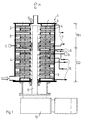
- the tempering apparatus 1 shown in fig. 1 comprise a cylindrical tempering column 2 with a cooling stage CO and a subsequent reheating stage RH for the continuos tempering of a fat-containing, chocolate-like mass M pumped through the column 2.
- the tempering column 2 further comprises a plurality of interconnected mass chambers 3, which are separated by intermediary heat exchange chambers 4 adapted to absorb heat from the mass chambers 3 or to submit heat to the mass chambers 3 during flow of cooling media through the heat exchange chambers of the cooling stage CO or during flow of heating media through the heat exchange chambers of the reheating stage RH during the flow of the mass M through the chambers and up through the column 2.
- the cooling media are conveyed to, respectively conveyed from the heat exchange chambers of the cooling stage CO via schematically shown tube connections 6, and the heating media are conveyed to, respectively conveyed from the heat exchange chambers of the reheating stage RH via schematically shown tube connections 7.
- Circuits adapted for control of temperature and flow of circulation of the heat exchange media to and from the chambers 4 are not shown and may be laid out and arranged in many ways as long as the above described tempering takes place.
- a part of the cooling circuit will normally comprise control means, which secures the provision of a plurality of heat exchange chambers 4 having a constant temperature Tk of the cooling media, thereby creating a pre-crystallisation zone at the adjacent mass chambers.
- the heat exchange media are circulated continuously through the heat exchange chambers 4.
- the mass temperature T1 is measured when the mass leaves the cooling stage, and is measured again by T2 when it leaves the reheating stage.
- the mass chambers 3 further comprises mixing and stirring elements 8, as shown in fig. 2 and 3, and which are rotated by a common drive shaft 9, which is arranged centrally in the column 2 and is powered by a motor 10.
- the mixing and stirring elements 8 each comprise two identical, plate shaped arms 11, which extends radially from a hub 12 and are positioned 180° from each other in relation to the axis.
- the number of plate shaped arms comprised by each stirring element could be 3 or 4 or more as well.
- the arms 11 are provided with upper and lower, axially extending mixing blades 13, 14, 15, 16; 17, 18, 19 20, which are plate shaped.
- the upper mixing blades 13, 14, 15, 16 extend radially in the opposite direction to the extension of the lower mixing blades 17, 18, 19, 20, as seen in the direction of the extension of the blades in the direction of rotation O of the mixing and stirring elements 8 or in the opposite direction, respectively.
- the upper mixing blades 13, 14, 15, 16 are laid out and arranged at the plate shaped arms 11 upper side in an opposite, laterally reversed manner, in relation to that of which the lower mixing blades 17, 18, 19, 20 are laid out and arranged at the lower side of the plate shaped arm 11.
- the mixing blades 13, 14, 15, 16; 17, 18, 19, 20 have a convex, curved extension in direction outwardly towards the peripheral cylinder wall 28, whereby the mass in excess of a radial shear force is influenced by a shear force in the direction of rotation O during mixing as well.
- the mixing blades 13, 14, 15, 16; 17, 18, 19, 20 extend from the leading edge 21 of the plate shaped arm 11 and to the trailing edge 22 of that.
- the mass chambers 3 are interconnected by means of openings 23 for the flow of mass therethrough, which openings 23 are arranged in the bottom of a chamber 3 close by the peripheral cylinder wall 28, and are arranged alternating and positioned 180° to each other from chamber 3 to chamber 3, seen in the direction of the flow of the mass through the column 2, which direction by the enclosed embodiment is upwards.
- the openings 23 for the flow of mass therethrough could as well be arranged at other areas of the bottom of the chamber 3, close by the hub or at the hub itself.
- An upper or lower mixing blade 13, 17 by the hub 12 of an mixing and stirring element 8 extend radially and uninterrupted from the hub 12 and forwards in the direction of rotation O of the mixing and stirring element 8, and an opening 24 for the flow of chocolate mass therethrough is provided in the plate shaped arm 11 of the mixing and stirring element 8 at a part 5 of the arm located between the mentioned inner mixing blade 13, 17 and the hub 12 itself, as depicted by fig. 2-4.
- an axial flow of the mass close to the drive shaft 9 and the hub 12, so that nests and zones of no stirring in the mass are avoided around the shaft 9, especially where the plate shaped arm 11 is connected with the hub 12.
- An especially expedient mixing and stirring in the zone of the mass close by the hub 12 is achieved when the opening 24 extends in essential close to the mixing blade as well as to the hub 12 at the mentioned part 5 of the arm located between the hub 12 and its connection with the uninterrupted extension of the mixing blade.
- Edge parts of the opening may expediently be curved, and some of the periphery perts 29 of the opening, could in their largest extension take the form of part of a circle with its centre at the axis of rotation of the drive shaft 8.
- the largest extension of the opening 24 could be in the direction of rotation O of the stirring element 8, i.e. fig. 2, for the provision of an uninterrupted flow through the opening.
- the upper and lower mixing blades 13, 14, 15, 16; 17, 18, 19, 20 constitutes at their ends horizontal surfaces 30, which are situated axially in distance of the upper and lower horizontal wall surfaces 31, respective 32 of the mass chamber, for the creation of gaps of a shear gradient intermediary the mentioned adjacent horizontal surfaces, through which gaps the mass passes during the rotation of the mixing and stirring elements as it essentially is known.
- shear gradient or often called the shear quotient is defined as the quotient of the difference in speed between the surfaces that demarcate the gap and the width of the gap.
- the quotient of shear is by experience between 250 s-1 and 7000 s-1.
- an upper or lower mixing blade 16; 20 arranged at the peripheral end of the mixing and stirring element at its end has a vertically extending end surface 27, which is situated radially in distance of the inner surfaces on the peripheral cylindrical wall 28 of the mass chamber, as shown in fig. 3, thereby providing a gap performing a shearing gradient between the end surface 27 and the cylinder wall 28, through which gap the mass flows when the mixing and stirring element 8 rotates in the mass chamber 3.
- a shear gradient is provided by a gap at the comparatively large cylindrical surface area at the peripheral cylinder wall 28 as well.
- a considerable increase of the total area of the gaps providing the shear gradient effect is obtained in comparison to that of the prior known temperers.
- improved mixing and stirring of the mass is achieved.
- the end surface 27 constitutes part of a cylindrical surface with essentially the same form as that of the cylindrical wall 28.
- the end surface 27 may further extend from the plate shaped arm 11 and to the upper or lower limitation of the mass chamber 3, respectively, whereby an optimally achievable area of shear gradient is provided at the cylinder wall 28.
- the mentioned upper or lower mixing blade 16; 20 arranged on the peripheral end of the mixing and stirring element 8 may comprise penetrations for the mass, and the end surface 27 may be arranged on an upper or lower essentially knob shaped part, 16' respectively 20'.
- the total surface area of the plate shaped arm 11 and of the mixing blades 13, 14, 15, 16; 17, 18, 19, 20 decreases gradually in direction out towards the peripheral cylinder wall 28.
- Testing has shown, that hereby is achieved a considerable more uniform stirring of the mass at all areas and zones of the chamber followed by an enhanced heat transport in the mass than was possible with the prior temperers.
- prior known tendency of the mass being dragged around in the chamber by the stirring element instead of moving relatively to that is eliminated.
- the total surface area of the mixing blades 13, 14, 15, 16; 17, 18, 19, 20 decreases gradually in direction out towards the peripheral cylinder wall 28 and/ or that the total surface area of the horizontal area of the mixing blades in the gaps of performing shear gradient, decreases gradually in direction out towards the peripheral cylinder wall 28.
- the friction between the mass and the adjacent surfaces of the gaps of shear are thereby adjusted to the in a most convenient manner to the velocity at a random radius of the arm 11, whereby an enhanced stirring follows.
- the direction of rotation may be the opposite, i.e. anti-clockwise as well, the above described advantages being maintained as well.
- the only difference concerning the function will be, that the mass will flow in the direction from above and down through the opening 24 in stead of from below and up through the opening 24 as being encountered when the stirring element rotates clockwise as depicted in fig. 2.
Landscapes
- Engineering & Computer Science (AREA)
- Physics & Mathematics (AREA)
- Thermal Sciences (AREA)
- Mechanical Engineering (AREA)
- General Engineering & Computer Science (AREA)
- Life Sciences & Earth Sciences (AREA)
- Chemical & Material Sciences (AREA)
- Food Science & Technology (AREA)
- Polymers & Plastics (AREA)
- Mixers Of The Rotary Stirring Type (AREA)
- Confectionery (AREA)
Claims (13)
- Dispositif (1) ayant une colonne de tempérage cylindrique (2) qui comprend une phase de refroidissement (CO) et une phase subséquente de réchauffage (RH) pour le tempérage continu d'une masse des matières grasses, de type chocolat, qui est pompée à travers, laquelle colonne de tempérage (2) comprend de plus un grand nombre de chambres de masse (3) reliées entre elles, qui sont séparées par des chambres intermédiaires d'échange de chaleur (4), qui sont adaptées pour absorber de la chaleur des chambres de masse (3) ou pour abandonner de la chaleur aux chambres de masse (3) pendant le passage du moyen de refroidissement par la phase de refroidissement (CO) ou pendant le passage du moyen de réchauffage par la phase de réchauffage (RH) respectivement, et lesquelles chambres de masse (3) comprennent de plus des éléments mélangeur/agitateur (8), qui sont tournées par l'action d'un arbre commun, central (9), placé dans la colonne (2), lesquels éléments mélangeur/agitateur (8) comprennent de plus au moins un bras radialement étendu en forme de plaque (11), qui comprend des ailes mélangeur supérieures et inférieures en forme de plaque, essentiellement verticalement étendues (13, 14, 15, 16; 17, 18, 19, 20), et lesquelles ailes mélangeur supérieures (13, 14, 15, 16) s'étendent radialement à l'opposé de l'extension des ailes mélangeur inférieures (17, 18, 19, 20), vu dans le sens de rotation ou dans le sens opposé respectivement des éléments mélangeur/agitateur (8), de plus comprenant qu'une aile mélangeur supérieure ou inférieure (13 respectivement 17), arrangée au moyeu (12) de l'élément mélangeur/agitateur (8), s'étend non interrompue du moyeu (12) et radialement vers le dehors dans le sens de rotation de l'élément mélangeur/agitateur (8) et qu'une ouverture (24) pour le passage de la masse de chocolat à travers est arrangée dans le bras en forme de plaque (11) de l'élément mélangeur/agitateur (8) à une partie (5) du bras se trouvant entre l'aile mélangeur intérieure mentionnée (13; 17) et le moyeu (12).
- Dispositif selon la revendication 1, dans lequel la périphérie (29) de l'ouverture (24) s'étend essentiellement près de l'aile mélangeur (13; 17) ainsi que du moyeu (12) dans la partie mentionnée (5) du bras (11) entre le moyeu (12) et la connexion avec l'extension non interrompue de l'aile mélangeur intérieure (13; 17).
- Dispositif selon la revendication 1, dans lequel les parties de bord (26) de l'ouverture (24), lesquelles parties sont les parties de devant pendant la rotation de l'élément mélangeur/agitateur (8) dans la masse, sont chanfreinées dans le sens du passage de la masse dans l'ouverture (24)
- Dispositif selon la revendication 1, dans lequel les parties de bord (25) de l'ouverture (24), lesquelles parties sont les parties d'arrière pendant la rotation de l'élément mélangeur/agitateur (8) dans la masse, sont chanfreinées dans le sens du passage de la masse hors de l'ouverture (24)
- Dispositif selon la revendication 1, dans lequel la périphérie (29) de l'ouverture (24) est recourbée.
- Dispositif selon la revendication 1, dans lequel la plus grande extension de l'ouverture (24) est dans le sens de rotation (O) de l'élément agitateur (8).
- Dispositif selon la revendication 1, dans lequel les ailes mélangeur supérieures (13, 14, 15, 16) sont disposées et arrangées sur le côté supérieur du bras en forme de plaque (11) de façon opposée, latéralement renversée, de laquelle sont disposées et arrangées les ailes mélangeur inférieures (17, 18, 19, 20) sur le côté inférieur du bras en forme de plaque (11).
- Dispositif selon la revendication 1, dans lequel une aile mélangeur/agitateur (8) comprend deux bras mélangeur/agitateur (11), essentiellement identiques, qui sont positionnés à un angle de 180° l'un avec l'autre.
- Dispositif selon la revendication 1, dans lequel les ailes mélangeur (13, 14, 15, 16; 17, 18, 19, 20) ont une extension convexe et recourbée dans la direction vers le paroi périphérique, cylindrique (28).
- Dispositif selon la revendication 1, dans lequel les ailes mélangeur (13, 14, 15, 16; 17, 18, 19, 20) s'étendent du bord de devant (21) et jusqu'au bord d'arrière (22) respectivement du bras en forme de plaque.
- Dispositif selon la revendication 1, dans lequel les chambres de masse (3) sont reliées entre elles par moyen des ouvertures de passage (23) situées dans le fond d'une chambre au paroi cylindrique périphérique (28).
- Dispositif selon la revendication 1, dans lequel les ouvertures de passage (23) au paroi cylindrique périphérique (28) sont situées alternativement et positionnées à 180° l'un avec l'autre, vu dans la direction du passage de la masse de la chambre (3) à la chambre (3) par la colonne (2).
- Dispositif selon la revendication 1, dans lequel les chambres de masse (3) sont reliées entre elles par moyen des ouvertures de passage (23) situées alternativement dans le fond des chambres de masse, au paroi cylindrique périphérique (28) et à l'arbre d'entraínement respectivement, vu dans la direction du passage de la masse de la chambre (3) à la chambre (3) par la colonne (2).
Applications Claiming Priority (3)
| Application Number | Priority Date | Filing Date | Title |
|---|---|---|---|
| DK55896 | 1996-05-09 | ||
| DK558/96 | 1996-05-09 | ||
| DK55896 | 1996-05-09 |
Publications (3)
| Publication Number | Publication Date |
|---|---|
| EP0806149A2 EP0806149A2 (fr) | 1997-11-12 |
| EP0806149A3 EP0806149A3 (fr) | 1999-08-25 |
| EP0806149B1 true EP0806149B1 (fr) | 2002-11-13 |
Family
ID=8094892
Family Applications (1)
| Application Number | Title | Priority Date | Filing Date |
|---|---|---|---|
| EP97201365A Expired - Lifetime EP0806149B1 (fr) | 1996-05-09 | 1997-05-07 | Appareil comprenant une colonne de conditionnement ou le conditionnement thermique continu de masses analogues au chocolat, contenant des graisses avec agitateur amélioré |
Country Status (3)
| Country | Link |
|---|---|
| US (2) | US5899562A (fr) |
| EP (1) | EP0806149B1 (fr) |
| DE (2) | DE69715956D1 (fr) |
Families Citing this family (16)
| Publication number | Priority date | Publication date | Assignee | Title |
|---|---|---|---|---|
| DE69803748T2 (de) * | 1998-03-16 | 2002-08-14 | Aasted-Mikroverk Aps, Farum | Vorrichtung zum kontinuierlichen Temperieren von schokoladenähnlicher Masse |
| DE69800725T2 (de) * | 1998-03-16 | 2001-08-09 | Aasted-Mikroverk Aps, Farum | Vorrichtung zum kontinuierlichen Tempern einer schokoladenähnlichen Masse |
| DE19849099C2 (de) * | 1998-10-24 | 2001-02-15 | Sollich Kg | Vorrichtung zum kontinuierlichen Temperieren von zu verarbeitenden kakaobutterhaltigen oder ähnlichen fetthaltigen Massen |
| DE19854204C2 (de) * | 1998-11-24 | 2000-06-15 | Sollich Gmbh & Co Kg | Vorrichtung zum kontinuierlichen Aufbereiten von zu verarbeitenden kakaobutterhaltigen oder ähnlichen fetthaltigen Massen |
| EP1050214B1 (fr) * | 1999-05-05 | 2004-10-13 | Aasted-Mikroverk Aps | Appareil de conditionnement |
| EP1050215B1 (fr) * | 1999-05-05 | 2004-10-13 | Aasted-Mikroverk Aps | Appareil de conditionnement |
| DK200000237U3 (da) * | 2000-07-25 | 2000-08-25 | Aasted Mikroverk Aps | Apparat til kontinuerlig temperering af chokolademasser |
| EP1356740B1 (fr) * | 2002-04-22 | 2006-07-19 | Aasted-Mikroverk Aps | Machine de moulage par compression sur convoyeur à bande pour articles de chocolaterie |
| DK1363098T3 (da) | 2002-04-22 | 2004-05-10 | Aasted Mikroverk Aps | Tempereringsapparat |
| EP1356741A1 (fr) * | 2002-04-22 | 2003-10-29 | Aasted-Mikroverk Aps | Appareil de fabrication d' articles de chocolat sur une bande de covoyage |
| US8562287B2 (en) * | 2009-06-23 | 2013-10-22 | Zoeller Pump Company, Llc | Grinder pump |
| USD653264S1 (en) * | 2010-04-05 | 2012-01-31 | Zoeller Pump Company, Llc | Cutter blade |
| EP2690966B8 (fr) | 2011-03-30 | 2023-11-08 | Barry Callebaut AG | Système de fabrication d'additifs et procédé d'impression permettant de personnaliser des confiseries en chocolat |
| US8986767B2 (en) | 2011-03-30 | 2015-03-24 | Stratsys, Inc. | Additive manufacturing system and method with interchangeable cartridges for printing customized chocolate confections |
| ES2691967T3 (es) * | 2016-07-15 | 2018-11-29 | Aasted Aps | Aparato para atemperado de masa de chocolate y nata |
| WO2020106397A1 (fr) * | 2018-11-20 | 2020-05-28 | Exxonmobil Upstream Research Company | Procédés et appareils pour l'amélioration des échangeurs de chaleur à parois raclées multiplaques |
Family Cites Families (11)
| Publication number | Priority date | Publication date | Assignee | Title |
|---|---|---|---|---|
| US2538466A (en) * | 1949-05-03 | 1951-01-16 | Marco John | Reactor for homogenizing machines |
| DE2536063C3 (de) * | 1975-08-13 | 1978-05-24 | Sollich Kg Spezialmaschinenfabrik, 4902 Bad Salzuflen | Temperiermaschine für kakaobutterhaltige und ähnliche fetthaltige Massen, insbesondere Schokolademassen |
| JPS5265360A (en) * | 1975-11-25 | 1977-05-30 | Kishihiro Yamaoka | Continuous kneading machine |
| US4648315A (en) * | 1985-11-19 | 1987-03-10 | Blum & Co., Maschinen- Und Apparatebau Gmbh | Device for tempering chocolate masses and the like |
| DE3714663A1 (de) * | 1987-05-02 | 1988-11-10 | Sollich Gmbh & Co Kg | Verfahren und vorrichtung zum kontinuierlichen aufbereiten von zu verarbeitenden kakaobutterhaltigen oder aehnlichen fetthaltigen massen |
| DK166005C (da) * | 1990-06-22 | 1993-08-02 | Aasted Mikroverk Aps | Chokoladetempereringsapparat |
| US4998464A (en) * | 1990-07-02 | 1991-03-12 | Process Systems Inc. | Heat exchange device for food |
| DK172603B1 (da) * | 1992-09-23 | 1999-02-22 | Aasted Mikroverk Aps | Fremgangsmåde og anlæg til fremstilling af chokoladeartikler |
| DK170963B1 (da) * | 1993-11-23 | 1996-04-09 | Aasted Mikroverk Aps | Apparat til temperering af chokoladelignende masser |
| DK171697B1 (da) * | 1994-05-31 | 1997-03-24 | Aasted Mikroverk Aps | Anlæg til fremstilling af skaller af flydende, tempererede og fedtholdige chokoladelignende masse, skaller fremstillet derved, levnedsmiddelartikler omfattende nævnte skaller samt anvendelse af nævnte skaller som indgående betanddele i levnedsmiddelartikler |
| DK171220B1 (da) * | 1994-06-03 | 1996-08-05 | Aasted Mikroverk Aps | Fremgangsmåde og apparat til kontinuerlig temperering af chokoladelignende masser |
-
1997
- 1997-05-07 DE DE69715956T patent/DE69715956D1/de not_active Expired - Lifetime
- 1997-05-07 EP EP97201365A patent/EP0806149B1/fr not_active Expired - Lifetime
- 1997-05-07 DE DE69716992T patent/DE69716992D1/de not_active Expired - Lifetime
- 1997-05-08 US US08/854,051 patent/US5899562A/en not_active Expired - Lifetime
- 1997-05-08 US US08/853,375 patent/US5850782A/en not_active Expired - Fee Related
Also Published As
| Publication number | Publication date |
|---|---|
| EP0806149A2 (fr) | 1997-11-12 |
| DE69715956D1 (de) | 2002-11-07 |
| US5850782A (en) | 1998-12-22 |
| EP0806149A3 (fr) | 1999-08-25 |
| US5899562A (en) | 1999-05-04 |
| DE69716992D1 (de) | 2002-12-19 |
Similar Documents
| Publication | Publication Date | Title |
|---|---|---|
| EP0806149B1 (fr) | Appareil comprenant une colonne de conditionnement ou le conditionnement thermique continu de masses analogues au chocolat, contenant des graisses avec agitateur amélioré | |
| US7237943B2 (en) | Dynamic fluid mixer | |
| CA1081687A (fr) | Echangeur thermique a double surface rainuree | |
| EP0806148B1 (fr) | Appareil comprenant une colonne de conditionnement pour le conditionnement thermique continu de masses analogues au chocolat, contenant des graisses soumises à des contraintes de cisaillement | |
| US6241377B1 (en) | Apparatus for continuously tempering chocolate masses and the like | |
| KR960013440A (ko) | 풀(糊) 제조장치 메인탱크 | |
| BRPI0517807B1 (pt) | processo para a produção de poliésteres e reator de disco anelar apropriado para tal | |
| EP1105219B1 (fr) | Dispositif d'entrainement pour separateur centrifuge | |
| EP0830889A1 (fr) | Dispositif à mélangeur conique comprenant au moins une vis de malaxage et un rotor horizontal à rotation rapide monté sur un arbre moteur | |
| EP1842009B1 (fr) | Four à convoyeur avec jets d'air | |
| US5934581A (en) | Mill for the fine grinding of solid particles in general and, particularly, of solid particles dispersed in a continuous lipid phase | |
| EP2740367B1 (fr) | Appareil de conditionnement des chocolats avec mélangeurs planétaires | |
| US3199574A (en) | Falling film-evaporators and rotor structure therefor | |
| DE19831087A1 (de) | Backofen mit Luftleitblech | |
| US4929152A (en) | Method and apparatus for maintaining a mixture of products at a certain temperature | |
| WO1997025579A1 (fr) | Echangeur de chaleur a racloirs de type ii | |
| EP0586402B1 (fr) | Procede et dispositif de transfert de chaleur ou de matiere | |
| US7357617B2 (en) | Fan including a plurality of spaced fan bodies | |
| CA1319096C (fr) | Precristalliseur | |
| JP4291930B2 (ja) | 高粘性生成物のための混合装置 | |
| SU1209941A1 (ru) | Устройство дл нагрева воздуха низкопотенциальным теплоносителем | |
| WO1997025578A1 (fr) | Echangeur de chaleur a racloirs de type i | |
| EP1050215B1 (fr) | Appareil de conditionnement | |
| US2257930A (en) | Apparatus for washing dishes, silverware, and the like | |
| SU1699591A1 (ru) | Экспозитор-коагул тор |
Legal Events
| Date | Code | Title | Description |
|---|---|---|---|
| PUAI | Public reference made under article 153(3) epc to a published international application that has entered the european phase |
Free format text: ORIGINAL CODE: 0009012 |
|
| AK | Designated contracting states |
Kind code of ref document: A2 Designated state(s): CH DE DK FR GB IT LI |
|
| PUAL | Search report despatched |
Free format text: ORIGINAL CODE: 0009013 |
|
| RIC1 | Information provided on ipc code assigned before grant |
Free format text: 6A 23G 1/18 A, 6A 23G 1/04 B |
|
| AK | Designated contracting states |
Kind code of ref document: A3 Designated state(s): CH DE DK FR GB IT LI |
|
| 17P | Request for examination filed |
Effective date: 20000214 |
|
| 17Q | First examination report despatched |
Effective date: 20010216 |
|
| GRAG | Despatch of communication of intention to grant |
Free format text: ORIGINAL CODE: EPIDOS AGRA |
|
| GRAG | Despatch of communication of intention to grant |
Free format text: ORIGINAL CODE: EPIDOS AGRA |
|
| GRAH | Despatch of communication of intention to grant a patent |
Free format text: ORIGINAL CODE: EPIDOS IGRA |
|
| GRAH | Despatch of communication of intention to grant a patent |
Free format text: ORIGINAL CODE: EPIDOS IGRA |
|
| GRAA | (expected) grant |
Free format text: ORIGINAL CODE: 0009210 |
|
| AK | Designated contracting states |
Kind code of ref document: B1 Designated state(s): CH DE DK FR GB IT LI |
|
| PG25 | Lapsed in a contracting state [announced via postgrant information from national office to epo] |
Ref country code: LI Free format text: LAPSE BECAUSE OF FAILURE TO SUBMIT A TRANSLATION OF THE DESCRIPTION OR TO PAY THE FEE WITHIN THE PRESCRIBED TIME-LIMIT Effective date: 20021113 Ref country code: IT Free format text: LAPSE BECAUSE OF FAILURE TO SUBMIT A TRANSLATION OF THE DESCRIPTION OR TO PAY THE FEE WITHIN THE PRESCRIBED TIME-LIMIT;WARNING: LAPSES OF ITALIAN PATENTS WITH EFFECTIVE DATE BEFORE 2007 MAY HAVE OCCURRED AT ANY TIME BEFORE 2007. THE CORRECT EFFECTIVE DATE MAY BE DIFFERENT FROM THE ONE RECORDED. Effective date: 20021113 Ref country code: FR Free format text: LAPSE BECAUSE OF FAILURE TO SUBMIT A TRANSLATION OF THE DESCRIPTION OR TO PAY THE FEE WITHIN THE PRESCRIBED TIME-LIMIT Effective date: 20021113 Ref country code: CH Free format text: LAPSE BECAUSE OF FAILURE TO SUBMIT A TRANSLATION OF THE DESCRIPTION OR TO PAY THE FEE WITHIN THE PRESCRIBED TIME-LIMIT Effective date: 20021113 |
|
| REG | Reference to a national code |
Ref country code: GB Ref legal event code: FG4D |
|
| REG | Reference to a national code |
Ref country code: CH Ref legal event code: EP |
|
| REF | Corresponds to: |
Ref document number: 69716992 Country of ref document: DE Date of ref document: 20021219 |
|
| PG25 | Lapsed in a contracting state [announced via postgrant information from national office to epo] |
Ref country code: DK Free format text: LAPSE BECAUSE OF FAILURE TO SUBMIT A TRANSLATION OF THE DESCRIPTION OR TO PAY THE FEE WITHIN THE PRESCRIBED TIME-LIMIT Effective date: 20030213 |
|
| PG25 | Lapsed in a contracting state [announced via postgrant information from national office to epo] |
Ref country code: DE Free format text: LAPSE BECAUSE OF FAILURE TO SUBMIT A TRANSLATION OF THE DESCRIPTION OR TO PAY THE FEE WITHIN THE PRESCRIBED TIME-LIMIT Effective date: 20030214 |
|
| PG25 | Lapsed in a contracting state [announced via postgrant information from national office to epo] |
Ref country code: GB Free format text: LAPSE BECAUSE OF NON-PAYMENT OF DUE FEES Effective date: 20030507 |
|
| REG | Reference to a national code |
Ref country code: CH Ref legal event code: PL |
|
| EN | Fr: translation not filed | ||
| PLBE | No opposition filed within time limit |
Free format text: ORIGINAL CODE: 0009261 |
|
| STAA | Information on the status of an ep patent application or granted ep patent |
Free format text: STATUS: NO OPPOSITION FILED WITHIN TIME LIMIT |
|
| 26N | No opposition filed |
Effective date: 20030814 |
|
| GBPC | Gb: european patent ceased through non-payment of renewal fee |
Effective date: 20030507 |