EP0806046B1 - Stabilisiertes abgereichertes uraniummaterial - Google Patents
Stabilisiertes abgereichertes uraniummaterial Download PDFInfo
- Publication number
- EP0806046B1 EP0806046B1 EP96909467A EP96909467A EP0806046B1 EP 0806046 B1 EP0806046 B1 EP 0806046B1 EP 96909467 A EP96909467 A EP 96909467A EP 96909467 A EP96909467 A EP 96909467A EP 0806046 B1 EP0806046 B1 EP 0806046B1
- Authority
- EP
- European Patent Office
- Prior art keywords
- uranium
- depleted uranium
- stabilized
- depleted
- weight percent
- Prior art date
- Legal status (The legal status is an assumption and is not a legal conclusion. Google has not performed a legal analysis and makes no representation as to the accuracy of the status listed.)
- Expired - Lifetime
Links
Images


Classifications
-
- G—PHYSICS
- G21—NUCLEAR PHYSICS; NUCLEAR ENGINEERING
- G21F—PROTECTION AGAINST X-RADIATION, GAMMA RADIATION, CORPUSCULAR RADIATION OR PARTICLE BOMBARDMENT; TREATING RADIOACTIVELY CONTAMINATED MATERIAL; DECONTAMINATION ARRANGEMENTS THEREFOR
- G21F1/00—Shielding characterised by the composition of the materials
- G21F1/02—Selection of uniform shielding materials
- G21F1/04—Concretes; Other hydraulic hardening materials
- G21F1/042—Concretes combined with other materials dispersed in the carrier
-
- G—PHYSICS
- G21—NUCLEAR PHYSICS; NUCLEAR ENGINEERING
- G21F—PROTECTION AGAINST X-RADIATION, GAMMA RADIATION, CORPUSCULAR RADIATION OR PARTICLE BOMBARDMENT; TREATING RADIOACTIVELY CONTAMINATED MATERIAL; DECONTAMINATION ARRANGEMENTS THEREFOR
- G21F1/00—Shielding characterised by the composition of the materials
- G21F1/02—Selection of uniform shielding materials
- G21F1/06—Ceramics; Glasses; Refractories
-
- G—PHYSICS
- G21—NUCLEAR PHYSICS; NUCLEAR ENGINEERING
- G21F—PROTECTION AGAINST X-RADIATION, GAMMA RADIATION, CORPUSCULAR RADIATION OR PARTICLE BOMBARDMENT; TREATING RADIOACTIVELY CONTAMINATED MATERIAL; DECONTAMINATION ARRANGEMENTS THEREFOR
- G21F1/00—Shielding characterised by the composition of the materials
- G21F1/02—Selection of uniform shielding materials
- G21F1/08—Metals; Alloys; Cermets, i.e. sintered mixtures of ceramics and metals
- G21F1/085—Heavy metals or alloys
-
- G—PHYSICS
- G21—NUCLEAR PHYSICS; NUCLEAR ENGINEERING
- G21F—PROTECTION AGAINST X-RADIATION, GAMMA RADIATION, CORPUSCULAR RADIATION OR PARTICLE BOMBARDMENT; TREATING RADIOACTIVELY CONTAMINATED MATERIAL; DECONTAMINATION ARRANGEMENTS THEREFOR
- G21F3/00—Shielding characterised by its physical form, e.g. granules, or shape of the material
-
- G—PHYSICS
- G21—NUCLEAR PHYSICS; NUCLEAR ENGINEERING
- G21F—PROTECTION AGAINST X-RADIATION, GAMMA RADIATION, CORPUSCULAR RADIATION OR PARTICLE BOMBARDMENT; TREATING RADIOACTIVELY CONTAMINATED MATERIAL; DECONTAMINATION ARRANGEMENTS THEREFOR
- G21F5/00—Transportable or portable shielded containers
- G21F5/005—Containers for solid radioactive wastes, e.g. for ultimate disposal
-
- G—PHYSICS
- G21—NUCLEAR PHYSICS; NUCLEAR ENGINEERING
- G21F—PROTECTION AGAINST X-RADIATION, GAMMA RADIATION, CORPUSCULAR RADIATION OR PARTICLE BOMBARDMENT; TREATING RADIOACTIVELY CONTAMINATED MATERIAL; DECONTAMINATION ARRANGEMENTS THEREFOR
- G21F1/00—Shielding characterised by the composition of the materials
- G21F1/02—Selection of uniform shielding materials
- G21F1/04—Concretes; Other hydraulic hardening materials
- G21F1/042—Concretes combined with other materials dispersed in the carrier
- G21F1/047—Concretes combined with other materials dispersed in the carrier with metals
-
- G—PHYSICS
- G21—NUCLEAR PHYSICS; NUCLEAR ENGINEERING
- G21F—PROTECTION AGAINST X-RADIATION, GAMMA RADIATION, CORPUSCULAR RADIATION OR PARTICLE BOMBARDMENT; TREATING RADIOACTIVELY CONTAMINATED MATERIAL; DECONTAMINATION ARRANGEMENTS THEREFOR
- G21F1/00—Shielding characterised by the composition of the materials
- G21F1/02—Selection of uniform shielding materials
- G21F1/10—Organic substances; Dispersions in organic carriers
- G21F1/103—Dispersions in organic carriers
- G21F1/106—Dispersions in organic carriers metallic dispersions
Definitions
- This invention relates to the field of radiation shielding for radioactive materials. More particularly, this invention relates to a stabilized depleted uranium material for attenuating gamma rays in radiation shielding materials.
- gamma radiation absorption Two important characteristics of radiation shielding with respect to radioactive materials are: (1) gamma radiation absorption and (2) neutron absorption.
- Gamma rays are quanta of electromagnetic wave energy similar to but of much higher energy than ordinary X-rays.
- Gamma rays are emitted by certain radioactive materials during the decay process and are highly penetrating, being absorbed only by adequate thicknesses of substantially dense matter, such as lead, heavy metals, and various forms of cement.
- Neutrons on the other hand, are uncharged elementary particles. Neutrons interact with matter primarily through collisions and are absorbed by materials exhibiting substantially large thermal neutron capture cross-sections.
- the present invention goes to the absorption of gamma radiation absorption; however, it is to be understood that the present invention may be practiced in combination with neutron absorption techniques known in the art.
- High-level radiative materials including liquids from reprocessing and spent (used) nuclear fuel, typically have half-lives of hundreds of thousands of years.
- the reprocessing material is generally stored as liquids, then solidified, permanently stored, and disposed of as required.
- Spent nuclear fuel is stored initially in water-cooled pools at the reactor sites awaiting shipment to a permanent disposal site. After about ten years, the fuel may be moved to dry storage containers until such time that a permanent disposal facility becomes available.
- radiation shielding means such as containers for storage and transport of radiative materials, should confine them safely for at least about 100 years, and preferably about 300 years.
- Lead has often been used for gamma ray shielding in radiation shielding means because it is dense, easily worked and relatively inexpensive.
- a lead shield can often be thinner and more compact than a comparable radiation shield made of almost any other material except depleted uranium. This ability to take up less space and be more portable is highly desirable for radiation shielding systems since it is often necessary to move the shielding systems, such as to more remote locations for safety purposes. Additionally, it is often desirable to build shielding systems in locations where there is limited space and available real estate for radioactive storage purposes is at a premium.
- concrete systems require great thicknesses to obtain the necessary shielding properties for radioactive materials; thus, concrete systems generally lack portability due to their high mass and substantial bulk, and limit the volume of radiative material that may be stored due to the space required for an adequate thickness of concrete.
- shielding characteristics may be improved by merely admixing depleted uranium metal or uranium oxides in a concrete, Yoshihisa et al., Japanese Patent Application Pub. No. 61-091598. While such approaches do have some potential for reducing the thickness of the radiation shielding material required there are serious chemical reactivity problems with these systems and the admixed depleted uranium or uranium oxide does not achieve as high a density as is desired. Most notably, the admixed depleted uranium or uranium oxide undergoes reactions in the concrete that results in the degradation of the concrete that prevents the concrete from obtaining the desired system life of one hundred years, particularly at elevated temperatures.
- a three layered structure has been employed to attempt to reduce the thickness concrete shielding, Suzuki et al., U.S. Patent No. 4,687,614.
- the three layered structure comprises a metallic vessel with a concrete lining and inner layer which is reinforced with a reinforcing material and strengthened with a polymeric impregnant, and a polymerized and cured impregnant layer as an intermediate layer between the metallic and concrete layers.
- this attempt like others, has generally been unsuccessful in achieving the desired size reduction, while maintaining the cost advantages, desired strength and other properties of conventional concrete systems.
- a radiation shielding concrete product comprising a stabilized depleted uranium material and a neutron absorbing component, the stabilized depleted uranium material and neutron absorbing component being present in the concrete product in sufficient amounts to provide a concrete having a density between 4 and 15 grams per cm 3 and that will, at a predetermined thickness, attenuate gamma rays and absorb neutrons from a radioactive material of projected gamma ray and neutron emissions over a determined time period.
- the stabilized depleted uranium material is stabilized such that degradation of the concrete is prevented at a temperature of 250°C for a period of at least one month when in an environment that would be saturated with water vapor at room temperature.
- a method of shielding radioactive material generating nuclear radiation comprising neutrons and gamma rays with a container containing gamma attenuating and neutron absorbing components comprises:
- a stabilized depleted uranium material for use in the above mentioned radiation shielding material comprises:
- the layer is formed by the reaction of the depleted uranium compound with a stabilizing agent, preferably wherein the stabilizing agent is an oxidizing agent that reacts with the depleted uranium compound to result in a product that is substantially water and air impermeable.
- the layer is formed by coating the particle with a coating material selected from the group consisting of cement, ceramic material, bituminous material, metal, composite, polymer cement, polymer, glass, and mixtures thereof.
- the stabilized depleted uranium material is formed into a densified aggregation of particles.
- Such a densified aggregate can be formed by binding a plurality of particles together with binding means to form an aggregate thereof.
- the binding means is preferably a member selected from the group consisting of glasses, polymers, cements, ceramics, bituminous materials, metals, composites, polymer cements, and mixtures thereof.
- a densified aggregate can also be formed by fusing a plurality of particles together.
- a densified aggregate can also be formed by sintering a plurality of said particles in a sintering material.
- Preferred sintering materials are selected from the group consisting of clay, soil, basalt, and mixtures thereof.
- the stabilized depleted uranium material also preferably comprises a neutron absorbing material selected from the group consisting of compounds of beryllium, boron, cadmium, hafnium, iridium, mercury, europium, gadolinium, samarium, dysprosium, erbium and lutetium and mixtures thereof.
- a neutron absorbing material selected from the group consisting of compounds of beryllium, boron, cadmium, hafnium, iridium, mercury, europium, gadolinium, samarium, dysprosium, erbium and lutetium and mixtures thereof.
- a method of making a stabilized depleted uranium material for use in the above mentioned radiation shielding material comprises the steps of:
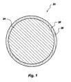
- FIG. 1 is an enlarged cross-sectional view of stabilized depleted uranium material made in accordance with the principles of the present invention, having an inherently stable surface layer.
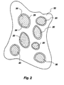
- FIG. 2 is a cross-sectional view of shielding material containing the invention of FIG. 1.
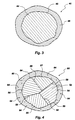
- FIG. 3 is an enlarged cross-sectional view of an alternative embodiment of the invention of FIG. 1, having a coating.
- FIG. 4 is an enlarged cross-sectional view of an alternative embodiment of the invention of FIG. 1, having a coating.
- FIG. 5 is a cross-sectional view of shielding material containing the invention of FIGS. 3 and 4.
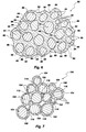
- FIG. 6 is an enlarged cross-sectional view of an alternative embodiment of the invention of FIG. 1, having an aggregate formed by densification.
- FIG. 7 is an enlarged cross-sectional view of an alternative embodiment of the invention of FIG. 1, having an aggregate formed by fusing.
- FIG. 8 is an enlarged cross-sectional view of an alternative embodiment of the invention of FIG. 1, having an aggregate formed by sintering.
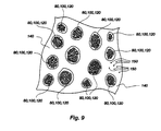
- FIG. 9 is a cross-sectional view of shielding material containing stabilized depleted uranium material of FIGS. 6-8.
- FIG. 10 is another cross-sectional view of shielding material containing stabilized depleted uranium material of FIGS. 6-8.
- FIG. 11 is a cross-sectional view of shielding material containing stabilized depleted uranium material of FIGS. 1, 4, and 6-8.
- the stable depleted uranium material of the present invention comprises at least one layer circumferentially disposed about the surface of a particle of depleted uranium compound which thereby causes the depleted uranium compound to be stable.
- the layer may be formed (a) due to the inherent properties of the product of the reaction of at least one stabilizing agent with at least one depleted uranium compound, (b) by coating at least one depleted uranium compound with at least one coating material, or (c) in the densification of at least one depleted uranium compound.
- Depleted uranium is a radioactive by-product produced in substantial quantities during the manufacture of fuel grade uranium i.e. enriched in U-235.
- depleted uranium compounds known to those skilled in the art are used.
- depleted uranium compounds include: depleted uranium oxides, such as UO 2 , UO 3 and U 3 O 8 ; depleted uranium silicides, such as U 3 Si 2 , U 3 Si, USi, U 2 Si 3 , and Usi 3 ; depleted uranium borides, such as UB 2 ; depleted uranium nitrides such as UN, UN 2 , and U 2 N 3 ; depleted uranium phosphides, such as UP, UP 2 , and U 3 P 4 ; depleted uranium sulfides, such as US, U 2 S 3 , U 3 S 5 , US 2 ; depleted uranium arsenides, such as UAs, U 3 As 4 , Uas 2 ; depleted uranium selenides, such as USe, U 3 Se 5 , U 2 Se 3 , USe 2 , and USe 3 ; de
- the present invention employs depleted uranium compounds, but in a stable form, thereby providing a useful stabilized depleted uranium material for shielding containers, structures, walls and the like.
- the stabilized radiation shielding composition of the present invention is a "stabilized depleted uranium material" for use in a “shielding material.”
- shielding material designates a material, such as concrete, ceramic, bituminous material, metal, composite, polymer cement, polymer glass, or water, containing at least one stabilized depleted uranium material and used for shielding radioactive materials.
- the shielding material may be for use in containers, structures and objects such as those indicated above.
- Radiation shielding devices such as containers, structures and objects are made from such shielding materials. Radiation shielding devices include: floors, walls, ceilings, roofs, windows, doors, hatches, buildings, silos, pads, foundations, footings, vessels, vaults, transportation containers, storage containers, canisters, pipes, valves, vats, housings, concretes, slags, mats, sheets, wires, bricks, pellets, rods, slugs, bars, fibers, and the like.
- Containers, structures, and objects having the stabilized depleted uranium material of the present invention have long-term durability, good handling properties, maximal internal capacity, good structural stability and minimal thickness.
- An especially desirable feature of this invention is the ability to utilize depleted uranium for a useful purpose, thus solving a serious disposal problem that exists around the world for depleted uranium.
- stable refers to chemical stability and is preferably defined as stabilized depleted uranium material that does not substantially degrade at a temperature between approximately 90°C and 250°C, and more preferably at 250°C, for a period of at least one month in an environment that is saturated in water vapor at room temperature.
- stabilized depleted uranium material is used to refer to:
- the present invention relates to the formation of stabilized depleted uranium material for use in a shielding material by forming a stable layer at the surface of particles of the depleted uranium compound.
- any stabilized depleted uranium material can be used in any shielding material for advantageously attenuating gamma rays.
- the shielding materials such as concrete, polymers, polymer cement, waxes and water, have inherent neutron attenuating qualities, an additional benefit when shielding radioactive materials.
- the particles of the present invention are not necessarily of any particular shape, and that the cross-sectional diameters of particles can vary substantially from one particle to another. It will further be appreciated that the particles of the present invention can vary substantially from the illustrative particle sizes, and that such particles may be larger or smaller than such particle dimensions discussed in association with each embodiment.
- FIG. 1 An illustrative embodiment of the present invention shown in figure 1 is a stabilized depleted uranium material generally indicated at 20 , which comprises a particle 24 of at least one depleted uranium compound having a stable surface layer 28 circumferentially disposed thereon.
- the stable surface layer 28 is the product of a reaction of depleted uranium compound and a stabilizing agent. This stable reaction product is disposed at least at the surface 26 , and possibly deeper into and including the entire particle 24 , to form at least an inherently stable layer 28 .
- the size of the depleted uranium compound particle 24 of the embodiment of figure 1 is generally in the range from approximately 5x10 -7 m (meters) to 5x10 -2 m, with preferred particle 24 size in the range from approximately 1x10 -3 m to 1x10 -2 m.
- the stabilizing agent can comprise any material that can be reacted with or impregnated into the surface 26 of the particle 24 , thereby causing at least the surface 26 of the particle 24 to be stable.
- depleted uranium silicides can be used for the formation of an inherently stable surface layer 28 on the particle 24 because the depleted uranium silicides can be combined with an oxygen based oxidizer (such as air, oxygen, or water) to form a stable layer 28 of amorphous silicon oxide (SiO 2 ).
- an oxygen based oxidizer such as air, oxygen, or water
- a particle 24 of depleted uranium sulfides or selenides can be oxidized to form at least a stable oxide surface layer 28 having good resistance to water and oxidation up to 300°C.
- a particle 24 of depleted uranium bismuthide can also be oxidized to form a stable surface layer 28 .
- stabilizing agents that form oxides from sulfides, selenides and bismuthides can comprise appropriate stabilizing agents.
- depleted uranium compounds that can form a stable surface layer 28 include depleted uranium nitrides, carbides, phosphides and arsenides as well as borides, tellurides and antimonides.
- stabilizing agents can include those agents that form oxides from nitrides, carbides, phosphides, and arsenides, borides, tellurides and antimonides may also be appropriate stabilizing agents.
- depleted uranium oxide appears to disadvantageously swell and the depleted uranium nitrides and carbides seem to react with water vapor at the surface.
- the depleted uranium phosphide and arsenide compounds appear to be somewhat more stable than the nitrides and carbides, and therefore may be preferable.
- the reaction forming at least a stable surface layer 28 on the particle 24 can occur before, at the time of, or after the inclusion of the depleted uranium compound in a shielding material 32 as shown in figure 2; provided that in those cases where the reaction forming the stable surface layer 28 occurs at the time of or after the inclusion of the depleted uranium compound particle 24 in the shielding material does not substantially reduce the structural integrity of the shielding material.
- depleted uranium silicide compounds can be reacted with oxygen, water or a similar oxidizing reagent to form at least a layer 28 of silicon oxide (SiO 2 ) on the particle 24 .
- Such reactions as may be carried out by those skilled in the art illustratively include the following: U x Si y + O 2 ⁇ U x Si y-1 + SiO 2 , or U x Si y + 2H 2 O ⁇ U x Si y-1 + SiO 2 + 2H 2 ; where x and y represent the atom ratio in the molecule of depleted uranium and silicon, respectively.
- FIG. 3 An alternative embodiment of the present invention shown in figure 3 is a stabilized depleted uranium material indicated generally at 40 which comprises a particle 44 of at least one depleted uranium compound, the surface 46 of which is coated with a coating material 48 which is stable and may further be substantially water and/or air impermeable material.
- a coating material 48 which is stable and may further be substantially water and/or air impermeable material.
- the coating material 48 does not necessarily contact the surface 46 of the depleted uranium compound particle 44 , but at least partially covers the particle 44 even though at least one layer of additional material is disposed between the surface 46 of the particle 44 and the coating material 48 .
- a particle 44 of depleted uranium compound is coated with a coating material 48 , which is a member selection from the group consisting of glasses, polymers, cements, ceramics, bituminous materials, metals, composites, polymer cements, and mixtures thereof.
- Suitable glasses include silicon dioxide glass, clay glass and mixtures thereof.
- Suitable polymers can include thermoplastic polymers, casting resins and polymers, and thermosetting resins and polymers, such as: ABS copolymers, allyl resins, amino resins, acetal resins, cellulose acetates, celluloses, epoxy resins, melamines, phenol-formaldehyde resins, phenolic resins, phenoxy resins, polyphenylenes, polypropylenes, polyacrylonitrile, polybutylenes, polycarbonate, polyethylene terephthalate, polyethylene (including cross-linked polyethylene), polyimides polymethacrylonitrile, polymethyl methacrylate, polymethylpentenes, polyolefins, polyphosphates, polystyrenes, polysulfones, polytetrafluoroethylene, polyurethane, polyvinyl butyrals, polyvinyl chloride, polyvinyl acetates, thermosetting resins, and ureas. Care must be taken to avoid a coating material 48
- the particle 44 is coated with a coating material 48 is shown in figure 3.
- the particle 44 of depleted uranium compound 48 can be formed from finely divided depleted uranium compound, comprising single crystal of depleted uranium compound.
- the stabilized depleted uranium material 50 of this alternative embodiment may comprise a particle 52 of depleted uranium material which comprises more than one crystal 54-57 of at least one depleted uranium compound, bounded together with narrow disorganized regions of common atoms at grain boundaries 58 between the crystals 54-57 ; the surface 59 of the particle 52 being coated with material 60 as discussed with respect to the embodiment of figure 3.
- the size of the depleted uranium compound particles 44 and 52 generally range from approximately 5x10 -6 m to 5x10 -2 m, with preferred particle size in the range from approximately 1x10 -3 m to 1x10 -2 m.
- the coating material 60 comprises neutron absorbing means, indicated at 64 , thus having the additional advantage of absorbing neutrons as well as shielding gamma radiation.
- Neutron absorbing components of the coating material 60 include hydrogen and oxygen.
- Additives to the coating material 60 that can further enhance neutron absorption include: beryllium, boron, cadmium, hafnium, iridium, mercury, europium, gadolinium, samarium, dysprosium, erbium and lutetium.
- the coating material 48 applied to the depleted uranium compound particle 44 by methods well known in the art of coating; which include forming at least one layer by at least one: bath, spray, extruder, die, mold, blower, roller, solution, emulsion, electrodeposition; and includes such techniques as: bathing, spraying, extruding, casting, molding (including use of injection and vacuum techniques), blowing, rolling, electroplating, fusing, mixing, hot powder coating, precipitating, laminating, calendaring, pressing, rolling, drop forming (where a droplet is formed about the particle), dry spinning (process of forcing a solution through holes in a spinneret and evaporating the solvent), dipping, melt spinning (process of forcing molten material through holes in a spinneret and cooling), pultrusion (process of dipping, passed through die, and curing), wet spinning (process of precipitation from solutions), thermoforming (process of formation using hot thermoplastic sheets), and similar coating processes.
- the coating material 48 may vary in thickness from a substantially thin film to a relatively thick layer as compared to the particle 44 size, and the coating material 48 may further vary from a substantially uniformly thick layer to a relatively non-uniformly thick layer. Finally, it is to be understood that the coating material 48 comprises at least one layer, and may comprise more than one layer, formed about the particle 44 .
- the stabilized depleted uranium material 40 or 50 of this embodiment may be disposed in a shielding material 62 .
- the depleted uranium compound comprises at least two particles disposed substantially close together such that at least one stable aggregate of depleted uranium compound which is "substantially dense” is formed.
- substantially dense it is meant that the density of aggregate can range from approximately 4 to 15 grams per cm 3 (cubic centimeter), yet the preferred density range for the aggregate is in the range from approximately 5 to 11 grams per cm 3 .
- Other alternative embodiments of the present invention include densifying particles of depleted uranium compound having an inherently stable layer or a coating within a binding means to form an aggregate; fusing the coatings of depleted uranium compound particles to form an aggregate; and, sintering particles of depleted uranium compound in a sintering material so as to form an aggregate.
- aggregates provide increased density of the depleted uranium, which is employed advantageously in shielding material.
- the particles of depleted uranium compound range generally from approximately 5x10 -7 m to 5x10 -2 m, with preferred particle size in the range from approximately 1x10 -3 m to 1x10 -2 m.
- the aggregate may have a cross-sectional diameter ranging generally from approximately 5x10 -4 m to 1x10 -1 m, and the preferred aggregate diameter is in the range from approximately 5x10 -3 m to 35x10 -3 m.
- an aggregate depicted generally as 80 , comprises at least two particles 84 of at least one depleted uranium compound having a surface 86 which comprises an inherently stable layer or stable coating, wherein the particles 84 are densified within a binding means 88 .
- the binding means 88 can comprise a number of different materials useful for binding the particles 84 together in a substantially dense aggregate 80 .
- the bindings means comprises those coating materials and a shielding materials such as those previously discussed above.
- the binding means 88 forms what may be considered as a cementitious phase of atoms between the particles 84 of depleted uranium compound, the cementitious phase of the binding means 88 containing some atoms of elements dissimilar to the atoms of the depleted uranium compound and binding the particles 84 together, forming a substantially dense aggregate 80 which can be employed advantageously in a shielding material.
- binding material 88 further comprises neutron absorbing means, indicated at 90 , such as those previously discussed.
- an aggregate depicted generally as 100
- an aggregate depicted generally as 100
- the fusing of the surfaces 108 may form regions where material is melded together, as shown at 112 , but may also form regions containing voids 116 . While the melded and void regions may exist within one aggregate 100 , it is preferable to avoid formation of voids 116 in order to obtain substantially dense material.
- the fused surfaces 108 in this embodiment of the invention can comprise the inherently stable surface layers formed on depleted uranium compound particles, as well as including coatings, as have been previously discussed in other embodiments herein.
- the fusing of the surfaces 108 forms a stable aggregate 100 of at least two particles 104 which is preferably substantially dense and can be employed advantageously in a shielding material.
- coatings 108 further comprises neutron absorbing means, indicated at 110 , such as those previously discussed.
- an aggregate depicted generally as 120
- the particles 124 comprising at least one depleted uranium compound.
- the particles 124 are sintered in a sintering material 128 so as to form the stable aggregate 120 .
- Sintering forms a substantially dense aggregate 120 which can be employed advantageously in a shielding material, shown in figures 9-10.
- the sintering process for producing the desired densification of particles 124 to form the aggregate 120 can include: (a) solid state sintering, (b) sintering aided by a liquid phase, also called liquid phase sintering; and (c) pressure aided sintering, also called hot pressing or hot isostatic pressing, where the solid or liquid phase sintering is aided by the concurrent application of pressure. Additionally, pressing the mixture of depleted uranium compound particles 124 and sintering material prior to sintering or after sintering, may be employed.
- All sintering takes place at temperatures lower than the melting point of the depleted uranium compound, even if a molten phase, or cementitious phase, of the sintering material is utilized. Also during sintering, one may expect some amount of grain growth in the depleted uranium compound.
- the aggregate 120 is also substantially dense and can be employed advantageously in a shielding material.
- An especially preferred uranium aggregate 120 according to this alternative embodiment of the invention due to its hardness, strength, stability, resistance to leaching and low cost is a finely divided depleted uranium compound which has been liquid phase sintered; where the sintering material comprises a material from the group which includes: clay, soil, and basalt.
- the aggregate 120 according to this embodiment comprises a sintered mixture of depleted uranium compound and one or more phases derived from a reactive liquid of the sintering material.
- the depleted uranium compound particles 124 are contained within the aggregate 120 of this embodiment in one or more of the following physical forms: (1) chemically bound in an amorphous or glass phase, (2) chemically bound in crystalline mineral phases; and, (3) at least one oxide phase physically surrounded by a crystalline and amorphous phase.
- the aggregate 120 has been found to resist water, steam, oxygen, chemical phases in Portland cement, and weak acids and bases.
- the sintering process for producing the aggregate 120 of this embodiment may additionally benefit from the application of pressure concurrent with the heating.
- the application of pressure in the sintering process has the advantage of eliminating the need for very fine particles 124 of depleted uranium compound material and/or sintering material, and also removes voids and pores which may arise due to nonuniform admixing of the depleted uranium compound particles 124 and sintering material.
- the sintering material 128 further comprises neutron absorbing means, indicated at 130 , such as those previously discussed.
- a liquid phase sintering process employs natural or synthetic basalt.
- the basalt is finely ground prior to heating to form the reactive liquid phase of the sintering material.
- the finely ground basalt generally has a size ranging generally from approximately 1x10 -6 m to 5x10 -5 m, with preferred particle 124 size in the range from approximately 5x10 -6 m to 2x10 -5 m.
- a preferred basalt would comprise a material comprising: (a) silicon oxide (e.g. SiO 2 ) in an amount between approximately 25 and 60 weight percent; (b) aluminum oxide (e.g. Al 2 O 3 ) in an amount between approximately 3 and 20 weight percent; (c) iron oxide (e.g.
- Fe 2 O 3 and/or Fe/O in an amount between approximately 10 and 30 weight percent;
- titanium oxide e.g. TiO 2
- zirconium oxide e.g. ZrO 2
- calcium oxide e.g. CaO
- magnesium oxide e.g. MgO
- sodium oxide e.g. Na 2 O
- potassium oxide e.g. K 2 O
- the weight percents are those of the sintering material based on the total weight of the composition thereof prior to the addition of any depleted uranium compound.
- the preferred liquid phase sintering process for a depleted uranium compound according to this embodiment is carried out at a temperature between approximately 1000°C and 1500°C in an oxidizing or reducing atmosphere; which is starkly different from normal solid state sintering of uranium dioxide powder which is carried out at about 1700°C in a vacuum or reducing atmosphere in the production of nuclear fuel.
- Clay is advantageous because it provides plasticity and binding properties to a mixture containing a finely divided depleted uranium compound, thus greatly aiding the "green" forming of the mixture prior to the firing application of heat in the furnace for sintering.
- Solid state sintering includes dry pressing and extrusion processes. With solid state sintering organic binders must be added to the depleted uranium compound particles in order to provide sufficient plasticity to form a green having sufficient density and strength to be handled prior to sintering.
- depleted uranium hexafluoride is hydrolyzed with water and precipitated as ammonium diuranate or ammonium uranyl carbonate, by addition of ammonia or ammonium carbonate respectively.
- the precipitate is dried and then calcined and reduced at 800°C in hydrogen to produce the depleted uranium compound, depleted uranium oxide as a powder.
- a coarse aggregate if formed by cold pressing a mixture of depleted uranium oxide and basalt to approximately 60% density. This is followed by sintering the mixture under pressure, the sintering being carried out at a temperature between approximately 1000°C and 1500°C in an oxidizing atmosphere such as air, the pressure being sufficient to produce an aggregate 120 having a density of approximately 5 to 11 grams per cm 3 .
- Another illustrative example of the practice of the present invention would be to mix the depleted uranium oxide powder and basalt with a small amount of polyvinyl alcohol and allow it to form into roughly spherical clumps under agitation by the "flying disk” process, and then sintering the clumps under pressure, the sintering being carried out at a temperature between approximately 1000°C and 1500°C in an oxidizing atmosphere of air, the pressure being sufficient to produce an aggregate 120 having a density of approximately 5 to 11 grams per cm 3 .
- an aggregate 80 , 100 , 120 such as those discussed in figures 6, 7, and 8, can be included in a shielding material 140 , such as concrete, ceramic, bituminous materials, metal, composite, polymer cements, polymer, glass or water.
- a shielding material 140 such as concrete, ceramic, bituminous materials, metal, composite, polymer cements, polymer, glass or water.
- the aggregate 80 , 100 , 120 may be admixed throughout the shielding material 140 , or as indicated in figure 10, the aggregate 80, 100, 120 may be placed in a compact configuration within the shielding material 140 .
- the shielding material 140 further comprises neutron absorbing means, indicated at 150 , such as those previously discussed.
- the shielding material 160 may include more than one form of stabilized depleted uranium material 20, 40, 50, 80, 100, 120 .
- Shielding materials may comprise at least one of the following: concrete, ceramic, bituminous materials, metal, composite, polymer cements, polymer, glass, water, and other such substances known by those skilled in the art. It is preferred that the shielding material further comprise a substance useful in attenuating and absorbing neutrons, such as those neutron absorption means discussed above. Specific illustrative examples of shielding materials useful in the practice of the present invention include: portland cement, polymers, sulfur polymer cement, waxes, water, bituminous materials, and metal.
- the shielding material comprises neutron absorbing means, such as those previously discussed.
- a stabilized depleted uranium material incorporated into a concrete shielding material is illustrated.
- Concrete incorporating depleted uranium oxide aggregate is produced by conventional means.
- Mix proportions for conventional heavy aggregate concretes are similar to those used for construction concretes. Such mix proportions are also suitable for use with the depleted uranium oxide aggregates.
- Mix proportions are 1 part cement, 2 parts sand, and 4 parts coarse aggregate by weight, with about 5.5 to 6 gallons of water per 94-lb bag of cement.
- Ordinary Portland cement (Portland Type I-II cement) is used.
- the water/cement ratio (which could affect neutron absorption) is selected to maximize the concrete strength.
- Uranium oxide aggregates are coated with a water and air impermeable coating to provide desired stability at elevated temperatures.
- Heavy mineral fines e.g., barite or magnetite sands
- Neutron absorbing additives such as boron compounds, e.g. boron carbide, boron frits, baron-containing glass, or B 2 O 3 ; hafnium compounds, e.g. HfO 2 ; or gadolinium compounds, e.g. Gd 2 O 3 , are also added as needed.
- the concrete shielding composition of this invention preferably contains reinforcing materials, such as steel bars, necessary to meet structural requirements for accidents and seismic events, reinforcing fillers and/or strengthening impregnants. These materials include steel fiber, glass fiber, polymer fiber, lath and reinforcing steel mesh.
- a UO 2 aggregate concrete using typical standard mix proportions, has a density of between about 6.8 and about 8.0 g/cm 3 (20 to 500 lb/ft 3 ), depending upon the density of the UO 2 aggregate and whether silica sand or barite sand is used.
- Depleted uranium oxide concrete has a much higher density than conventional heavy aggregate concretes or construction concretes (Table (1). Since the shielding advantage for gamma radiation is approximately proportional to the density of the concrete, a unit thickness of depleted UO 2 concrete provides an average of 1.8 times the shielding of conventional heavy aggregate concrete (contains barite, magnetite or limonite as a replacement for conventional gravel aggregate) and 3.2 times that for construction concrete.
- UO 2 aggregate concrete provides significant container weight savings.
- a vendor of spent fuel storage casks uses a 73.7 cm (29 inch) thickness of conventional concrete 24 g/cm 3 (150 lb/ft 3 ) as a radiation shield.
- the 179 cm (70.5 inch) inside diameter concrete cask contains an inner metal container holding 24 PWR spent fuel elements has an outside diameter of 328 cm (129 inches).
- a depleted UO 2 concrete cask, having the same 179 cm (70.5 inch) inside diameter has an outside diameter of about 229 cm (90 inches).
- the potential smaller size of the UO 2 concrete cask makes it easier to manufacture (e.g., lower form costs, etc.) and transport, as compared to a cask made from conventional concrete.
- Another cost benefit of this invention utilizing depleted uranium aggregate is the costs that are avoided by not having to continue to store depleted UF 6 gas in pressurized containers. There are also costs associated with the potential for release to the environment and other possible safety issues that are avoided. In addition, the stored UF 6 will eventually have to be processed for disposal or some other use.
Landscapes
- Engineering & Computer Science (AREA)
- Physics & Mathematics (AREA)
- General Engineering & Computer Science (AREA)
- High Energy & Nuclear Physics (AREA)
- Ceramic Engineering (AREA)
- Metallurgy (AREA)
- Chemical & Material Sciences (AREA)
- Dispersion Chemistry (AREA)
- Compositions Of Macromolecular Compounds (AREA)
- Solid-Sorbent Or Filter-Aiding Compositions (AREA)
- Inorganic Compounds Of Heavy Metals (AREA)
- Curing Cements, Concrete, And Artificial Stone (AREA)
Claims (45)
- Ein strahlungsabschirmendes Betonerzeugnis, das ein stabilisiertes abgereichertes Uranmaterial und eine neutronenabsorbierende Komponente umfaßt, wobei das abgereicherte Uranmaterial und die neutronenabsorbierende Komponente in dem Betonerzeugnis in ausreichender Menge vorliegen, um einen Beton bereitzustellen, der eine Dichte zwischen 4 und 15 Gramm pro cm3 aufweist und der bei einer vorbestimmten Dicke von einem radioaktivem Material mit ausgesandter Gammastrahlung und Neutonenemission über einen bestimmten Zeitraum Gammastrahlen abschwächt und Neutronen absorbiert.
- Erzeugnis nach Anspruch 1, wobei das stabilisierte abgereicherte Uranmaterial so beschichtet wird, daß es ausreichend stabil ist, so daß der Beton bei einer Temperatur von 250°C zumindest einen Monat lang vor Abbau geschützt ist, wenn er in einer Umgebung ist, die bei Raumtemperatur mit Wasserdampf gesättigt wäre.
- Erzeugnis nach Anspruch 2, wobei das stabilisierte abgereicherte Uranmaterial eine abgereicherte Uranverbindung umfaßt, die aus folgender Gruppe gewählt wird: Uranoxide, Uransilicide, Uranboride, Urannitride, Uranphosphide, Uransulfide, Uranasenide, Uranselenide, Urantelluride, Urankarbide, Uranbismuthide, Uranantimonide und eine Mischung daraus.
- Erzeugnis nach Anspruch 2, wobei das stabilisierte abgereicherte Uranmaterial eine gesinterte Mischung aus einer fein zerteilten abgereicherten Uranverbindung und zumindest einer Phase, die von einer reaktiven Flüssigkeit abgeleitet wird, umfaßt.
- Erzeugnis nach Anspruch 4, worin die gesinterte Mischung durch eine Flüssigphasensintertechnik erhalten werden kann und das stabilisierte abgereicherte Uranmaterial eine abgereicherte Uranverbindung umfaßt, die ein Uranoxid umfaßt.
- Erzeugnis nach Anspruch 4, worin das reaktive Gas erhalten werden kann, indem zumindest ein Bestandteil aus folgender Gruppe: Schlicker, Erde, Basalt und einer Mischung daraus, erhitzt wird.
- Erzeugnis nach Anspruch 6, wobei die abgereicherte Uranverbindung ein Uranoxid umfaßt und die reaktive Flüssigkeit erhalten werden kann, indem fein zerteilter Basalt erhitzt wird, wobei der Basalt eine Zusammensetzung aufweist, die umfaßt:(a) 25 bis 60 Gew.-% Siliciumoxid,(b) 3 bis 20 Gew.-% Aluminiumoxid,(c) zwischen 10 und 30 Gew.-% Eisenoxid,(d) zwischen 0 und 30 Gew.-% Titanoxid,(e) zwischen 0 und 15 Gew.-% Zirkonoxid,(f) zwischen 0 und 15 Gew.-% Calciumoxid,(g) zwischen 0 und 5 Gew.-% Magnesiumoxid,(h) zwischen 0 und 5 Gew.-% Natriumoxid, und(i) zwischen 0 und 5 Gew.-% Kaliumoxid.
- Erzeugnis nach Anspruch 7, wobei das gesinterte Material erhalten werden kann, indem ein Flüssigphasensinterprozeß bei einer Temperatur zwischen 1000 und 1500°C durchgeführt wird.
- Verfahren nach Anspruch 2, wobei das abgereicherte Uranaggregat mit einer Schutzbeschichtung beschichtet wird.
- Erzeugnis nach Anspruch 2, wobei die neutronenabsorbierende Komponente aus folgender Gruppe gewählt wird: Wasserstoff und Verbindungen von Bor, Hafnium, Gadolinium, Beryllium, Kadmium, Iridium, Quecksilber, Europium, Samarium, Dysprosium, Erbium und Lutetium.
- Verfahren zum Abschirmen von radioaktiven Materialien, die nukleare Strahlung erzeugen, die Neutronen- und Gammastrahlen umfaßt, mit einem Behälter, der gammaabschwächende und neutronenabsorbierende Komponenten enthält, wobei das Verfahren umfaßt:(a) Bestimmen des Massevolumens des radioaktiven Materials und der ausgesandten Menge an Radioaktivität, die von dem radioaktiven Material in Form von Gammastrahlen und Neutronen in einer bestimmten Zeit emittiert wird;(b) Bereiten eines Behälters zum Lagern des radioaktiven Materials, der einen eingeschlossenen Lagerraum umfaßt, der von einer Schicht eines strahlungsabschirmenden Betonerzeugnisses umgeben ist, der eine vorbestimmte Dicke aufweist, wobei der Beton ein stabilisiertes abgereichertes Uranmaterial und eine neutronenabsorbierende Komponente umfaßt, wobei das stabilisierte abgereicherte Uranmaterial und die neutronenabsorbierende Komponente in solch einer ausreichenden Menge vorliegen, so daß ein Beton mit einer Dichte zwischen 4 und 10 Gramm pro cm3 vorliegt, und der bei der bestimmten Dicke Gammastrahlen und Neutronen abschwächen und absorbieren wird, die ausgesandt werden, um von dem Massevolumen an radioaktivem Material in der bestimmten Zeit emittiert zu werden; und(c) Plazieren und Versiegeln des Massevolumens an radioaktiven Material in dem eingeschlossenen Lagerraum des Behälters.
- Erzeugnis nach einem der Ansprüche 1 bis 10, das umfaßt:ein stabilisiertes abgereichertes Uranmaterial,zumindest ein Partikel einer abgereicherten Uranverbindung, wobei das Partikel eine Oberfläche aufweist; undeine Schicht, die um die Oberfläche des Partikels angeordnet ist, wobei die Schicht bei einer Temperatur zwischen 90 und 250°C einen Monat lang in einer Umgebung, die bei Raumtemperatur mit Wasserdampf gesättigt sein würde, nicht wesentlich abgebaut wird.
- Stabilisiertes abgereichertes Uranmaterial nach Anspruch 12, wobei die abgereicherte Uranverbindung aus folgender Gruppe gewählt wird: Uransilicide, Uranboride, Urannitride, Uranphosphide, Uransulfide, Uranasenide, Uranselenide, Urantelluride, Urankarbide, Uranbismuthide, Uranantimonide und eine Mischung daraus.
- Stabilisiertes abgereichertes Uranmaterial nach Anspruch 13, wobei die Schicht durch die Reaktion der abgereicherten Uranverbindung mit einem Stabilisiermittel gebildet wird.
- Stabilisiertes abgereichertes Uranmaterial nach Anspruch 14, wobei die abgereicherte Uranverbindung Uransilicid umfaßt, und das stabilisierte abgereicherte Uranmaterial in ein strahlungsabschirmendes Material, das Beton umfaßt, gemischt wird.
- Stabilisiertes abgereichertes Uranmaterial nach Anspruch 14, wobei das stabilisierende Mittel ein Oxidiermittel ist, das mit der abgereicherten Uranverbindung reagiert und so zu einem Produkt führt, das im wesentlichen wasser- und luftimpermeabel ist.
- Stabilisiertes abgereichertes Uranmaterial nach Anspruch 12, wobei die Schicht durch Beschichten des Partikels mit einem Beschichtungsmaterial, das aus folgender Gruppe gewählt wird, gebildet wird: Zement, keramisches Material, bituminöses Material, Metall, Verbundwerkstoff, Polymerzement, Polymer, Glas und eine Mischung daraus.
- Stabilisiertes abgereichertes Uranmaterial nach Anspruch 17, wobei das Beschichtungsmaterial ein neutronenabsorbierendes Material aus folgender Gruppe umfaßt: Verbindungen aus Beryllium, Bor, Kadmium, Hafnium, Iridium, Quecksilber, Europium, Gadolinium, Samarium, Dysprosium, Erbium, Lutetium, und einer Mischung daraus.
- Stabilisiertes abgereichertes Uranmaterial nach Anspruch 12, das weiter umfaßt:
ein Bindemittel zum Zusammenbinden einer Vielzahl von Partikeln, um daraus ein Aggregat zu bilden. - Stabilisiertes abgereichertes Uranmaterial nach Anspruch 19, wobei das Bindemittel aus folgender Gruppe gewählt wird: Gläser, Polymere, Zemente, Keramiken, bituminöse Materialien, Metalle, Verbundwerkstoffe, Polymerzemente, und eine Mischung daraus.
- Stabilisiertes abgereichertes Uranmaterial nach Anspruch 20, wobei das Bindemittel weiter ein neutronenabsorbierendes Material umfaßt, das aus folgender Gruppe gewählt wird: Verbindungen aus Beryllium, Bor, Kadmium, Iridium, Quecksilber, Europium, Gadolinium, Samarium, Dysprosium, Erbium und Lutetium und einer Mischung daraus.
- Stabilisiertes abgereichertes Uranmaterial nach Anspruch 12, wobei zumindest zwei der Partikel zusammengeschmolzen werden, um daraus ein Aggregat zu bilden.
- Stabilisiertes abgereichertes Uranmaterial nach Anspruch 22, wobei das Aggregat weiter ein neutronenabsorbierendes Material umfaßt, das aus folgender Gruppe gewählt wird: Verbindungen aus Beryllium, Bor, Kadmium, Hafnium, Iridium, Quecksilber, Europium, Gadolinium, Samarium, Dysprosium, Erbium und Lutetium und einer Mischung daraus.
- Stabilisiertes abgereichertes Uranmaterial nach Anspruch 12, wobei eine Vielzahl der Partikel in einem Sintermaterial gesintert werden, um daraus ein stabiles Aggregat zu bilden.
- Stabilisiertes abgereichertes Uranmaterial nach Anspruch 24, wobei die Vielzahl der Partikel erhalten werden kann, indem sie bei einer Temperatur zwischen 1000 und 1500°C gesintert werden.
- Stabilisiertes abgereichertes Uranmaterial nach Anspruch 25, wobei das Sintermaterial aus folgender Gruppe gewählt wird: Schlicker, Erde, Basalt und eine Mischung daraus.
- Stabilisiertes abgereichertes Uranmaterial nach Anspruch 26, wobei das Sintermaterial Basalt ist, umfassend:
(a) 25 bis 60 Gew.-% Siliciumoxid; (b) 3 bis 20 Gew.-% Aluminiumoxid; (c) 10 bis 30 Gew.-% Eisenoxid; (d) 0 bis 30 Gew.-% Titanoxid; (e) 0 bis 15 Gew.-% Zirkonoxid; (f) 0 bis 15 Gew.-% Calciumoxid; (g) 0 bis 5 Gew.-% Magnesiumoxid; (h) 0 bis 5 Gew.-% Natriumoxid; (i) 0 bis 5 Gew.-% Kaliumoxid; und wobei die Gewichtsprozente die des Sintermaterials in bezug auf das Gesamtgewicht vor dem Zusatz der abgereicherten Uranverbindung sind. - Stabilisiertes abgereichertes Uranmaterial nach Anspruch 24, wobei das Sintermaterial weiter ein neutronenabsorbierendes Material umfaßt und aus folgender Gruppe gewählt wird: Verbindungen aus Beryllium, Bor, Kadmium, Hafnium, Iridium, Quecksilber, Europium, Gadolinium, Samarium, Dysprosium, Erbium und Lutetium und einer Mischung daraus.
- Verfahren nach Anspruch 11, in dem das stabilisierte abgereicherte Uranmaterial durch ein Verfahren hergestellt wird, das die Schritt umfaßt:(i) Bereitstellen eines Partikels einer abgereicherten Uranverbindung, wobei das Partikel eine Oberfläche aufweist; und(ii) Ausbilden einer Schicht, die um die Oberfläche des Partikels herum angeordnet ist, wobei die Schicht bei einer Temperatur von zwischen 90 bis 250°C einen Monat lang in einer Umgebung, die bei Raumtemperatur mit Wasserdampf gesättigt wäre,im wesentlichen nicht abgebaut wird.
- Verfahren nach Anspruch 28, wobei die abgereicherte Uranverbindung aus folgender Gruppe gewählt wird: Uransilicide, Uranboride, Urannitride, Uranphosphide, Uransulfide, Uranarsenide, Uranselenide, Urantelluride, Urankarbide, Uranbismuthide, Uranantimonide und einer Mischung daraus.
- Verfahren nach Anspruch 29, wobei die Schicht durch eine Reaktion der abgereicherten Uranverbindung mit einem Stabilisiermittel gebildet wird.
- Verfahren nach Anspruch 30, wobei die abgereicherte Uranverbindung Uransilicid umfaßt und das stabilisierte abgereicherte Uranmaterial in ein Strahlungsabschirmmaterial, das Beton umfaßt, gemischt wird.
- Verfahren nach Anspruch 30, wobei das Stabilisiermittel ein Oxidiermittel ist, das mit der abgereicherten Uranverbindung reagiert, was ein Erzeugnis ergibt, das im wesentlichen für Wasser und Luft impermeabel ist.
- Verfahren nach Anspruch 28, wobei die Schicht durch Beschichten der Partikel mit einem Beschichtungsmaterial gebildet wird, das aus folgender Gruppe gewählt wird: Zement, keramisches Material, bituminöses Material, Metall, Verbundwerkstoff, Polymerzement, Polymer, Glas und einer Mischung daraus.
- Verfahren nach Anspruch 33, wobei das Beschichtungsmaterial ein neutronenabsorbierendes Material umfaßt, das aus folgender Gruppe gewählt wird: Verbindungen von Beryllium, Bor, Kadmium, Hafnium, Iridium, Quecksilber, Europium, Gadolinium, Samarium, Dysprosium, Erbium, Lutetium und einer Mischung daraus.
- Verfahren nach Anspruch 28, wobei das stabilisierte abgereicherte Uranmaterial weiter umfaßt: ein Bindemittel, um eine Vielzahl der Partikel zusammenzubinden, um daraus ein Aggregat zu bilden.
- Verfahren nach Anspruch 35, wobei das Bindemittel aus folgender Gruppe gewählt wird: Gläser, Polymere, Zemente, Keramiken, bituminöse Materialien, Metalle, Verbundwerkstoffe, Polymerzemente und eine Mischung daraus.
- Verfahren nach Anspruch 36, wobei das Bindemittel weiter ein neutronenabsorbierendes Material umfaßt, das aus folgender Gruppe gewählt wird: Verbindungen aus Beryllium, Bor, Kadmium, Hafnium, Iridium, Quecksilber, Europium, Gadolinium, Samarium, Dysprosium, Erbium und Lutetium und einer Mischung daraus.
- Verfahren nach Anspruch 28, wobei zumindest zwei der Partikel zusammengeschmolzen werden, um daraus ein Aggregat zu bilden.
- Verfahren nach Anspruch 38, wobei das Aggregat weiter ein neutronenabsorbierendes Material umfaßt, das aus folgender Gruppe gewählt wird: Verbindungen aus Beryllium, Bor, Kadmium, Hafnium, Iridium, Quecksilber, Europium, Gadolinium, Samarium, Dysprosium, Erbium und Lutetium und einer Mischung daraus.
- Verfahren nach Anspruch 28, wobei eine Vielzahl der Partikel in einem Sintermaterial gesintert werden, um ein stabiles Aggregat daraus zu bilden.
- Verfahren nach Anspruch 40, wobei die Vielzahl der Partikel bei einer Temperatur zwischen 1000 und 1500°C gesintert werden.
- Verfahren nach Anspruch 41, wobei das Sintermaterial aus folgender Gruppe gewählt wird: Schlicker, Erde, Basalt und einer Mischung daraus.
- Verfahren nach Anspruch 42, wobei das Sintermaterial Basalt ist, und umfaßt: (a) 25 bis 60 Gew.-% Siliciumoxid; (b) 3 bis 20 Gew.-% Aluminiumoxid; (c) 10 bis 30 Gew.-% Eisenoxid; (d) 0 bis 30 Gew.-% Titanoxid; (e) 0 bis 15 Gew.-% Zirkonoxid; (f) 0 bis 15 Gew.-% Calciumoxid; (g) 0 bis 5 Gew.-% Magnesiumoxid; (h) 0 bis 5 Gew.-% Natriumoxid; (i) 0 bis 5 Gew.-% Kaliumoxid; wobei die Gewichtsprozente die des Sintermaterials in bezug auf das Gesamtgewicht vor der Zugabe der abgereicherten Uranverbindung sind.
- Stabilisiertes abgereichertes Uranmaterial nach Anspruch 40, wobei das Sintermaterial weiter ein neutronenabsorbierendes Material umfaßt, das aus folgender Gruppe gewählt wird: Verbindungen von Beryllium, Bor, Kadmium, Hafnium, Iridium, Quecksilber, Europium, Gadolinium, Samarium, Dysprosium, Erbium und Lutetium und einer Mischung daraus.
Applications Claiming Priority (3)
| Application Number | Priority Date | Filing Date | Title |
|---|---|---|---|
| US378161 | 1995-01-23 | ||
| US08/378,161 US5786611A (en) | 1995-01-23 | 1995-01-23 | Radiation shielding composition |
| PCT/US1996/000903 WO1996023310A1 (en) | 1995-01-23 | 1996-01-23 | Stabilized depleted uranium material |
Publications (3)
| Publication Number | Publication Date |
|---|---|
| EP0806046A1 EP0806046A1 (de) | 1997-11-12 |
| EP0806046A4 EP0806046A4 (de) | 1998-04-22 |
| EP0806046B1 true EP0806046B1 (de) | 2000-05-17 |
Family
ID=23491994
Family Applications (1)
| Application Number | Title | Priority Date | Filing Date |
|---|---|---|---|
| EP96909467A Expired - Lifetime EP0806046B1 (de) | 1995-01-23 | 1996-01-23 | Stabilisiertes abgereichertes uraniummaterial |
Country Status (7)
| Country | Link |
|---|---|
| US (2) | US5786611A (de) |
| EP (1) | EP0806046B1 (de) |
| AT (1) | ATE193147T1 (de) |
| AU (1) | AU5295196A (de) |
| CA (1) | CA2211145A1 (de) |
| DE (1) | DE69608415D1 (de) |
| WO (1) | WO1996023310A1 (de) |
Cited By (1)
| Publication number | Priority date | Publication date | Assignee | Title |
|---|---|---|---|---|
| WO2019050701A1 (en) * | 2017-09-05 | 2019-03-14 | Westinghouse Electric Company Llc | COMPOSITE FUEL WITH INCREASED OXIDATION RESISTANCE |
Families Citing this family (71)
| Publication number | Priority date | Publication date | Assignee | Title |
|---|---|---|---|---|
| US5786611A (en) * | 1995-01-23 | 1998-07-28 | Lockheed Idaho Technologies Company | Radiation shielding composition |
| US6120706A (en) * | 1998-02-27 | 2000-09-19 | Bechtel Bwxt Idaho, Llc | Process for producing an aggregate suitable for inclusion into a radiation shielding product |
| US5949084A (en) * | 1998-06-30 | 1999-09-07 | Schwartz; Martin W. | Radioactive material storage vessel |
| TW444209B (en) * | 1998-12-24 | 2001-07-01 | Hitachi Ltd | Radioactive material dry storage facility |
| USD433125S (en) * | 1999-06-03 | 2000-10-31 | Michael Bono | Shield for an aerosol dispensing device |
| US6153164A (en) * | 1999-10-04 | 2000-11-28 | Starmet Corporation | Method for producing uranium oxide from uranium tetrafluoride and a phyllosilicate mineral |
| DE59903429D1 (de) * | 1999-12-15 | 2002-12-19 | Gnb Gmbh | Verfahren zum Herstellen eines Transport- und/oder Lagerbehälters für radioaktive Gegenstände |
| US6805815B1 (en) * | 2000-05-24 | 2004-10-19 | Hanford Nuclear Service, Inc. | Composition for shielding radioactivity |
| US6518477B2 (en) | 2000-06-09 | 2003-02-11 | Hanford Nuclear Services, Inc. | Simplified integrated immobilization process for the remediation of radioactive waste |
| US6608315B1 (en) | 2000-11-01 | 2003-08-19 | Kourosh Saadatmand | Mechanism for prevention of neutron radiation in ion implanter beamline |
| US20020165082A1 (en) * | 2001-02-23 | 2002-11-07 | Dileep Singh | Radiation shielding phosphate bonded ceramics using enriched isotopic boron compounds |
| US6741669B2 (en) * | 2001-10-25 | 2004-05-25 | Kenneth O. Lindquist | Neutron absorber systems and method for absorbing neutrons |
| JP3951685B2 (ja) * | 2001-11-30 | 2007-08-01 | 株式会社日立製作所 | 中性子遮蔽材及び使用済み燃料収納容器 |
| US6919576B2 (en) * | 2002-02-04 | 2005-07-19 | Bechtel Bwxt Idaho Llc | Composite neutron absorbing coatings for nuclear criticality control |
| US6740260B2 (en) | 2002-03-09 | 2004-05-25 | Mccord Stuart James | Tungsten-precursor composite |
| US7760432B2 (en) * | 2002-04-25 | 2010-07-20 | Honeywell International Inc. | Photochromic resistant materials for optical devices in plasma environments |
| US7014059B2 (en) * | 2002-05-17 | 2006-03-21 | Master Lite Security Products, Inc. | Explosion resistant waste container |
| US6565647B1 (en) | 2002-06-13 | 2003-05-20 | Shieldcrete Ltd. | Cementitious shotcrete composition |
| DE10228387B4 (de) * | 2002-06-25 | 2014-10-16 | Polygro Trading Ag | Behältersystem zum Transport und zur Lagerung hochradioaktiver Materialien |
| US6891179B2 (en) * | 2002-10-25 | 2005-05-10 | Agilent Technologies, Inc. | Iron ore composite material and method for manufacturing radiation shielding enclosure |
| US6967343B2 (en) | 2002-10-25 | 2005-11-22 | Agilent Technologies, Inc. | Condensed tungsten composite material and method for manufacturing and sealing a radiation shielding enclosure |
| US7309807B2 (en) * | 2003-02-28 | 2007-12-18 | The Nanosteel Company, Inc. | Method of containing radioactive contamination |
| US7250119B2 (en) * | 2004-05-10 | 2007-07-31 | Dasharatham Sayala | Composite materials and techniques for neutron and gamma radiation shielding |
| US7638783B2 (en) * | 2004-05-22 | 2009-12-29 | Resin Systems Corporation | Lead free barium sulfate electrical insulator and method of manufacture |
| US20050258404A1 (en) * | 2004-05-22 | 2005-11-24 | Mccord Stuart J | Bismuth compounds composite |
| NO20044434D0 (no) * | 2004-10-19 | 2004-10-19 | Nuclear Prot Products As | Lang-tids lagringscontainer og fremgangsmate for fremstilling av denne |
| US20070102672A1 (en) | 2004-12-06 | 2007-05-10 | Hamilton Judd D | Ceramic radiation shielding material and method of preparation |
| US20070194256A1 (en) * | 2005-05-10 | 2007-08-23 | Space Micro, Inc. | Multifunctional radiation shield for space and aerospace applications |
| US7312466B2 (en) * | 2005-05-26 | 2007-12-25 | Tdy Industries, Inc. | High efficiency shield array |
| US7436932B2 (en) * | 2005-06-24 | 2008-10-14 | Varian Medical Systems Technologies, Inc. | X-ray radiation sources with low neutron emissions for radiation scanning |
| US7286626B2 (en) * | 2005-12-15 | 2007-10-23 | Battelle Energy Alliance, Llc | Neutron absorbing coating for nuclear criticality control |
| RU2320036C2 (ru) * | 2006-01-23 | 2008-03-20 | Федеральное государственное унитарное предприятие "Всероссийский научно-исследовательский институт неорганических материалов имени академика А.А. Бочвара" | Радиационно-защитная композиция, заполнитель на основе диоксида урана для ее получения и способ получения заполнителя |
| CN100999401A (zh) * | 2006-12-28 | 2007-07-18 | 吕迎智 | 一种减弱质子辐射强度的防护工程混凝土 |
| EP2355108B1 (de) | 2010-02-08 | 2012-11-14 | Technische Universität München | Abschirmungsmaterial und Abschirmungselement zur Abschirmung von Gamma- und Neutronenstrahlung |
| FR2961414B1 (fr) * | 2010-06-16 | 2012-06-15 | Commissariat Energie Atomique | Chambre de reaction de matiere exothermique |
| US8263952B1 (en) | 2010-06-22 | 2012-09-11 | Mccord Stuart J | Lead free barium sulfate electrical insulator and method of manufacture |
| US11373774B2 (en) | 2010-08-12 | 2022-06-28 | Holtec International | Ventilated transfer cask |
| US11887744B2 (en) | 2011-08-12 | 2024-01-30 | Holtec International | Container for radioactive waste |
| US10811154B2 (en) | 2010-08-12 | 2020-10-20 | Holtec International | Container for radioactive waste |
| WO2013115881A2 (en) * | 2011-11-14 | 2013-08-08 | Holtec International, Inc. | Method for storing radioactive waste, and system for implementing the same |
| US8450707B1 (en) * | 2011-03-22 | 2013-05-28 | Jefferson Science Associates, Llc | Thermal neutron shield and method of manufacture |
| US8664630B1 (en) * | 2011-03-22 | 2014-03-04 | Jefferson Science Associates, Llc | Thermal neutron shield and method of manufacture |
| RU2522673C2 (ru) * | 2012-08-06 | 2014-07-20 | Российская Федерация, от имени которой выступает Государственная корпорация по атомной энергии "Росатом"-Госкорпорация "Росатом" | Пастообразный материал для защиты от нейтронного излучения и способ приготовления пастообразного материала для защиты от нейтронного излучения |
| JP6310244B2 (ja) * | 2013-12-06 | 2018-04-11 | 日立造船株式会社 | 放射性物質収納用キャスクの製造方法 |
| US10026513B2 (en) | 2014-06-02 | 2018-07-17 | Turner Innovations, Llc. | Radiation shielding and processes for producing and using the same |
| US11715575B2 (en) | 2015-05-04 | 2023-08-01 | Holtec International | Nuclear materials apparatus and implementing the same |
| WO2017030577A1 (en) * | 2015-08-19 | 2017-02-23 | Danny Warren | Composition for radiation shielding |
| JP6685110B2 (ja) * | 2015-11-13 | 2020-04-22 | 株式会社エスイー | 放射線遮蔽用コンクリートとその製造方法 |
| JP2017156283A (ja) * | 2016-03-03 | 2017-09-07 | 株式会社東芝 | 中性子吸収体および臨界事故の防止方法 |
| CN107767980A (zh) * | 2016-08-19 | 2018-03-06 | 中国辐射防护研究院 | 一种远程充水式管道辐射热点屏蔽装置 |
| TWI616895B (zh) * | 2016-10-24 | 2018-03-01 | 行政院原子能委員會核能研究所 | 製備低放射性廢棄物處置容器之混凝土配比 |
| CN107455906B (zh) * | 2017-09-14 | 2020-11-03 | 浙江金华威达日化包装实业有限公司 | 内部可视的遮光指甲油瓶 |
| US11676736B2 (en) * | 2017-10-30 | 2023-06-13 | Nac International Inc. | Ventilated metal storage overpack (VMSO) |
| WO2019089582A1 (en) | 2017-11-03 | 2019-05-09 | Holtec International | Method of storing high level radioactive waste |
| KR20190088214A (ko) * | 2018-01-18 | 2019-07-26 | 에스케이하이닉스 주식회사 | 반도체 소자의 항공운송을 위한 중성자 차폐용 포장체 |
| US10692618B2 (en) | 2018-06-04 | 2020-06-23 | Deep Isolation, Inc. | Hazardous material canister |
| GB201810951D0 (en) * | 2018-07-04 | 2018-08-15 | Rolls Royce Plc | A nuclear power plant |
| CN110870950B (zh) * | 2018-08-31 | 2025-02-21 | 中硼(厦门)医疗器械有限公司 | 中子捕获治疗系统 |
| US10878974B2 (en) | 2018-12-14 | 2020-12-29 | Rad Technology Medical Systems, Llc | Shielding facility and method of making thereof |
| US10943706B2 (en) | 2019-02-21 | 2021-03-09 | Deep Isolation, Inc. | Hazardous material canister systems and methods |
| US10878972B2 (en) | 2019-02-21 | 2020-12-29 | Deep Isolation, Inc. | Hazardous material repository systems and methods |
| US20220384064A1 (en) * | 2019-11-11 | 2022-12-01 | Unm Rainforest Innovations | Polymer Concrete for Integrated Radiation Shielding |
| WO2022169472A2 (en) * | 2020-04-21 | 2022-08-11 | University Of Florida Research Foundation | Boron-doped cement and concrete |
| CN116134552A (zh) * | 2020-07-27 | 2023-05-16 | 株式会社东芝 | 放射线屏蔽体、放射线屏蔽体的制造方法及放射线屏蔽结构体 |
| US10941274B1 (en) | 2020-09-01 | 2021-03-09 | King Abdulaziz University | Nanoparticle-infused ABS filament for 3D-printed materials and uses for neutron detection and discrimination |
| CN112002453B (zh) * | 2020-09-07 | 2022-06-28 | 成都赐进金属材料有限公司 | 一种抗辐射的复合球及其制备方法 |
| CN114436619B (zh) * | 2020-11-03 | 2023-09-01 | 南京航空航天大学 | 一种高碳化硼含量磷酸镁基中子屏蔽胶凝材料 |
| CN113035385B (zh) * | 2021-03-04 | 2024-04-09 | 上海核工程研究设计院股份有限公司 | 一种含硼硅化铀整体型可燃毒物芯块 |
| ES2940568B2 (es) * | 2021-11-04 | 2024-12-30 | Ingecid Investig Y Desarrollo De Proyectos S L | Contenedor para residuos radioactivos |
| CN114171215B (zh) * | 2021-12-01 | 2025-01-07 | 中国核电工程有限公司 | 一种中子毒物材料及其制备方法、以及核临界安全贮槽 |
| FR3132590B1 (fr) | 2022-02-07 | 2025-02-21 | Orano | Procédé de préparation d’un matériau cimentaire de blindage contre les rayonnements ionisants |
Family Cites Families (21)
| Publication number | Priority date | Publication date | Assignee | Title |
|---|---|---|---|---|
| US3447938A (en) * | 1966-08-08 | 1969-06-03 | V R B Associates Inc | Lightweight high-strength cement compositions |
| US3547709A (en) * | 1968-05-14 | 1970-12-15 | Atomic Energy Commission | Corrosion-resistant uranium |
| US4123392A (en) * | 1972-04-13 | 1978-10-31 | Chemtree Corporation | Non-combustible nuclear radiation shields with high hydrogen content |
| US4257912A (en) * | 1978-06-12 | 1981-03-24 | Westinghouse Electric Corp. | Concrete encapsulation for spent nuclear fuel storage |
| JPS5985999A (ja) * | 1982-11-08 | 1984-05-18 | 秩父セメント株式会社 | 多重型容器およびその製造方法 |
| DE3310233A1 (de) * | 1983-03-22 | 1984-10-04 | Strabag Bau-AG, 5000 Köln | Behaeltnis zur lagerung radioaktiver elemente |
| JPS6191598A (ja) * | 1984-10-12 | 1986-05-09 | 日本原子力事業株式会社 | 放射線遮蔽体 |
| US4780269A (en) * | 1985-03-12 | 1988-10-25 | Nutech, Inc. | Horizontal modular dry irradiated fuel storage system |
| US4868400A (en) * | 1987-09-02 | 1989-09-19 | Chem-Nuclear Systems, Inc. | Ductile iron cask with encapsulated uranium, tungsten or other dense metal shielding |
| US4869866A (en) * | 1987-11-20 | 1989-09-26 | General Electric Company | Nuclear fuel |
| US4869867A (en) * | 1987-11-25 | 1989-09-26 | General Electric Company | Nuclear fuel |
| JPH032695A (ja) * | 1989-05-31 | 1991-01-09 | Nisshin Steel Co Ltd | 高除熱性の放射線しゃへい材 |
| JP3012671B2 (ja) * | 1990-08-03 | 2000-02-28 | 日本核燃料開発株式会社 | 核燃料ペレットの製造方法 |
| US5156804A (en) * | 1990-10-01 | 1992-10-20 | Thermal Technology, Inc. | High neutron-absorbing refractory compositions of matter and methods for their manufacture |
| US5242631A (en) * | 1992-01-13 | 1993-09-07 | Westinghouse Electric Corp. | Method for coating nuclear fuel pellets |
| US5334847A (en) * | 1993-02-08 | 1994-08-02 | The United States Of America As Represented By The Department Of Energy | Composition for radiation shielding |
| JP2761700B2 (ja) * | 1993-03-29 | 1998-06-04 | 原子燃料工業株式会社 | 重コンクリートの製造方法 |
| US5402455A (en) * | 1994-01-06 | 1995-03-28 | Westinghouse Electric Corporation | Waste containment composite |
| US5786611A (en) * | 1995-01-23 | 1998-07-28 | Lockheed Idaho Technologies Company | Radiation shielding composition |
| US5832392A (en) * | 1996-06-17 | 1998-11-03 | The United States Of America As Represented By The United States Department Of Energy | Depleted uranium as a backfill for nuclear fuel waste package |
| US5949084A (en) * | 1998-06-30 | 1999-09-07 | Schwartz; Martin W. | Radioactive material storage vessel |
-
1995
- 1995-01-23 US US08/378,161 patent/US5786611A/en not_active Expired - Fee Related
-
1996
- 1996-01-23 WO PCT/US1996/000903 patent/WO1996023310A1/en not_active Ceased
- 1996-01-23 AU AU52951/96A patent/AU5295196A/en not_active Abandoned
- 1996-01-23 AT AT96909467T patent/ATE193147T1/de not_active IP Right Cessation
- 1996-01-23 CA CA002211145A patent/CA2211145A1/en not_active Abandoned
- 1996-01-23 DE DE69608415T patent/DE69608415D1/de not_active Expired - Lifetime
- 1996-01-23 EP EP96909467A patent/EP0806046B1/de not_active Expired - Lifetime
-
1998
- 1998-07-28 US US09/123,979 patent/US6166390A/en not_active Expired - Fee Related
Cited By (1)
| Publication number | Priority date | Publication date | Assignee | Title |
|---|---|---|---|---|
| WO2019050701A1 (en) * | 2017-09-05 | 2019-03-14 | Westinghouse Electric Company Llc | COMPOSITE FUEL WITH INCREASED OXIDATION RESISTANCE |
Also Published As
| Publication number | Publication date |
|---|---|
| US6166390A (en) | 2000-12-26 |
| WO1996023310A1 (en) | 1996-08-01 |
| DE69608415D1 (de) | 2000-06-21 |
| ATE193147T1 (de) | 2000-06-15 |
| US5786611A (en) | 1998-07-28 |
| AU5295196A (en) | 1996-08-14 |
| EP0806046A4 (de) | 1998-04-22 |
| EP0806046A1 (de) | 1997-11-12 |
| CA2211145A1 (en) | 1996-08-01 |
Similar Documents
| Publication | Publication Date | Title |
|---|---|---|
| EP0806046B1 (de) | Stabilisiertes abgereichertes uraniummaterial | |
| US7250119B2 (en) | Composite materials and techniques for neutron and gamma radiation shielding | |
| SK14972000A3 (sk) | Žiareniu odolná, teplom tvrditeľná kompozícia | |
| CN112551951A (zh) | 防辐射混凝土组合物、制备方法及预制容器 | |
| US5416333A (en) | Medium density hydrogenous materials for shielding against nuclear radiation | |
| GB2048554A (en) | Process for conditioning radioactive and/or toxic waste | |
| CN107500677A (zh) | 一种γ射线屏蔽复合材料及其制备方法 | |
| US3983050A (en) | Method for storage of solid waste | |
| US5146047A (en) | Electric-wave absorbing material for construction | |
| Paul et al. | The use of surrogates in waste immobilization studies: a case study of plutonium | |
| US3106535A (en) | Neutron radiation shielding material | |
| JP2520978B2 (ja) | 放射線遮蔽材 | |
| US4261756A (en) | Lead alloy and granulate concrete containing the same | |
| Dole et al. | Radiation shielding using depleted uranium oxide in nonmetallic matrices | |
| JP6664639B2 (ja) | 放射線遮蔽体 | |
| Jostsons et al. | Synroc for immobilising excess weapons plutonium | |
| CA1226380A (en) | Method of packaging radioactive waste | |
| JPS6051071B2 (ja) | 原子炉用制御棒 | |
| JP2761700B2 (ja) | 重コンクリートの製造方法 | |
| GB2211834A (en) | Radiation shielding concrete composition | |
| US7012168B1 (en) | Boron-based containment matrix for the storage or transmutation of long-life radioactive elements | |
| JPS58208699A (ja) | 放射線を遮蔽・制御するfrp及び高分子樹脂積層成型構造物 | |
| JPH0244295A (ja) | 中性子遮蔽材料 | |
| Permar et al. | Significance of radiation effects in solid radioactive waste | |
| Lokken | Review of radioactive waste immobilization in concrete |
Legal Events
| Date | Code | Title | Description |
|---|---|---|---|
| PUAI | Public reference made under article 153(3) epc to a published international application that has entered the european phase |
Free format text: ORIGINAL CODE: 0009012 |
|
| 17P | Request for examination filed |
Effective date: 19970822 |
|
| AK | Designated contracting states |
Kind code of ref document: A1 Designated state(s): AT BE CH DE DK ES FR GB GR IE IT LI LU MC NL PT SE |
|
| A4 | Supplementary search report drawn up and despatched |
Effective date: 19980305 |
|
| AK | Designated contracting states |
Kind code of ref document: A4 Designated state(s): AT BE CH DE DK ES FR GB GR IE IT LI LU MC NL PT SE |
|
| RAP1 | Party data changed (applicant data changed or rights of an application transferred) |
Owner name: LOCKHEED MARTIN IDAHO TECHNOLOGIES COMPANY |
|
| 17Q | First examination report despatched |
Effective date: 19980807 |
|
| GRAG | Despatch of communication of intention to grant |
Free format text: ORIGINAL CODE: EPIDOS AGRA |
|
| GRAG | Despatch of communication of intention to grant |
Free format text: ORIGINAL CODE: EPIDOS AGRA |
|
| GRAH | Despatch of communication of intention to grant a patent |
Free format text: ORIGINAL CODE: EPIDOS IGRA |
|
| GRAH | Despatch of communication of intention to grant a patent |
Free format text: ORIGINAL CODE: EPIDOS IGRA |
|
| GRAA | (expected) grant |
Free format text: ORIGINAL CODE: 0009210 |
|
| AK | Designated contracting states |
Kind code of ref document: B1 Designated state(s): AT BE CH DE DK ES FR GB GR IE IT LI LU MC NL PT SE |
|
| PG25 | Lapsed in a contracting state [announced via postgrant information from national office to epo] |
Ref country code: NL Free format text: LAPSE BECAUSE OF FAILURE TO SUBMIT A TRANSLATION OF THE DESCRIPTION OR TO PAY THE FEE WITHIN THE PRESCRIBED TIME-LIMIT Effective date: 20000517 Ref country code: LI Free format text: LAPSE BECAUSE OF FAILURE TO SUBMIT A TRANSLATION OF THE DESCRIPTION OR TO PAY THE FEE WITHIN THE PRESCRIBED TIME-LIMIT Effective date: 20000517 Ref country code: IT Free format text: LAPSE BECAUSE OF FAILURE TO SUBMIT A TRANSLATION OF THE DESCRIPTION OR TO PAY THE FEE WITHIN THE PRESCRIBED TIME-LIMIT;WARNING: LAPSES OF ITALIAN PATENTS WITH EFFECTIVE DATE BEFORE 2007 MAY HAVE OCCURRED AT ANY TIME BEFORE 2007. THE CORRECT EFFECTIVE DATE MAY BE DIFFERENT FROM THE ONE RECORDED. Effective date: 20000517 Ref country code: ES Free format text: THE PATENT HAS BEEN ANNULLED BY A DECISION OF A NATIONAL AUTHORITY Effective date: 20000517 Ref country code: CH Free format text: LAPSE BECAUSE OF FAILURE TO SUBMIT A TRANSLATION OF THE DESCRIPTION OR TO PAY THE FEE WITHIN THE PRESCRIBED TIME-LIMIT Effective date: 20000517 Ref country code: BE Free format text: LAPSE BECAUSE OF FAILURE TO SUBMIT A TRANSLATION OF THE DESCRIPTION OR TO PAY THE FEE WITHIN THE PRESCRIBED TIME-LIMIT Effective date: 20000517 Ref country code: AT Free format text: LAPSE BECAUSE OF FAILURE TO SUBMIT A TRANSLATION OF THE DESCRIPTION OR TO PAY THE FEE WITHIN THE PRESCRIBED TIME-LIMIT Effective date: 20000517 |
|
| REF | Corresponds to: |
Ref document number: 193147 Country of ref document: AT Date of ref document: 20000615 Kind code of ref document: T |
|
| REG | Reference to a national code |
Ref country code: IE Ref legal event code: FG4D Ref country code: CH Ref legal event code: EP |
|
| REF | Corresponds to: |
Ref document number: 69608415 Country of ref document: DE Date of ref document: 20000621 |
|
| PG25 | Lapsed in a contracting state [announced via postgrant information from national office to epo] |
Ref country code: SE Free format text: LAPSE BECAUSE OF FAILURE TO SUBMIT A TRANSLATION OF THE DESCRIPTION OR TO PAY THE FEE WITHIN THE PRESCRIBED TIME-LIMIT Effective date: 20000817 Ref country code: PT Free format text: LAPSE BECAUSE OF FAILURE TO SUBMIT A TRANSLATION OF THE DESCRIPTION OR TO PAY THE FEE WITHIN THE PRESCRIBED TIME-LIMIT Effective date: 20000817 Ref country code: DK Free format text: LAPSE BECAUSE OF FAILURE TO SUBMIT A TRANSLATION OF THE DESCRIPTION OR TO PAY THE FEE WITHIN THE PRESCRIBED TIME-LIMIT Effective date: 20000817 |
|
| PG25 | Lapsed in a contracting state [announced via postgrant information from national office to epo] |
Ref country code: GR Free format text: LAPSE BECAUSE OF FAILURE TO SUBMIT A TRANSLATION OF THE DESCRIPTION OR TO PAY THE FEE WITHIN THE PRESCRIBED TIME-LIMIT Effective date: 20000818 Ref country code: DE Free format text: LAPSE BECAUSE OF FAILURE TO SUBMIT A TRANSLATION OF THE DESCRIPTION OR TO PAY THE FEE WITHIN THE PRESCRIBED TIME-LIMIT Effective date: 20000818 |
|
| ET | Fr: translation filed | ||
| NLV1 | Nl: lapsed or annulled due to failure to fulfill the requirements of art. 29p and 29m of the patents act | ||
| REG | Reference to a national code |
Ref country code: CH Ref legal event code: PL |
|
| PGFP | Annual fee paid to national office [announced via postgrant information from national office to epo] |
Ref country code: FR Payment date: 20010111 Year of fee payment: 6 |
|
| PG25 | Lapsed in a contracting state [announced via postgrant information from national office to epo] |
Ref country code: LU Free format text: LAPSE BECAUSE OF NON-PAYMENT OF DUE FEES Effective date: 20010123 Ref country code: IE Free format text: LAPSE BECAUSE OF NON-PAYMENT OF DUE FEES Effective date: 20010123 Ref country code: GB Free format text: LAPSE BECAUSE OF NON-PAYMENT OF DUE FEES Effective date: 20010123 |
|
| PG25 | Lapsed in a contracting state [announced via postgrant information from national office to epo] |
Ref country code: MC Free format text: LAPSE BECAUSE OF NON-PAYMENT OF DUE FEES Effective date: 20010131 |
|
| PLBE | No opposition filed within time limit |
Free format text: ORIGINAL CODE: 0009261 |
|
| STAA | Information on the status of an ep patent application or granted ep patent |
Free format text: STATUS: NO OPPOSITION FILED WITHIN TIME LIMIT |
|
| 26N | No opposition filed | ||
| GBPC | Gb: european patent ceased through non-payment of renewal fee |
Effective date: 20010123 |
|
| REG | Reference to a national code |
Ref country code: IE Ref legal event code: MM4A |
|
| PG25 | Lapsed in a contracting state [announced via postgrant information from national office to epo] |
Ref country code: FR Free format text: LAPSE BECAUSE OF NON-PAYMENT OF DUE FEES Effective date: 20020930 |
|
| REG | Reference to a national code |
Ref country code: FR Ref legal event code: ST |