EP0805957B1 - Procede et appareil de gravure en creux - Google Patents
Procede et appareil de gravure en creux Download PDFInfo
- Publication number
- EP0805957B1 EP0805957B1 EP96902715A EP96902715A EP0805957B1 EP 0805957 B1 EP0805957 B1 EP 0805957B1 EP 96902715 A EP96902715 A EP 96902715A EP 96902715 A EP96902715 A EP 96902715A EP 0805957 B1 EP0805957 B1 EP 0805957B1
- Authority
- EP
- European Patent Office
- Prior art keywords
- intaglio
- engraving
- recited
- pattern
- cylinder
- Prior art date
- Legal status (The legal status is an assumption and is not a legal conclusion. Google has not performed a legal analysis and makes no representation as to the accuracy of the status listed.)
- Expired - Lifetime
Links
Images


Classifications
-
- B—PERFORMING OPERATIONS; TRANSPORTING
- B41—PRINTING; LINING MACHINES; TYPEWRITERS; STAMPS
- B41C—PROCESSES FOR THE MANUFACTURE OR REPRODUCTION OF PRINTING SURFACES
- B41C1/00—Forme preparation
- B41C1/02—Engraving; Heads therefor
- B41C1/04—Engraving; Heads therefor using heads controlled by an electric information signal
- B41C1/045—Mechanical engraving heads
-
- H—ELECTRICITY
- H04—ELECTRIC COMMUNICATION TECHNIQUE
- H04N—PICTORIAL COMMUNICATION, e.g. TELEVISION
- H04N1/00—Scanning, transmission or reproduction of documents or the like, e.g. facsimile transmission; Details thereof
- H04N1/04—Scanning arrangements, i.e. arrangements for the displacement of active reading or reproducing elements relative to the original or reproducing medium, or vice versa
- H04N1/17—Scanning arrangements, i.e. arrangements for the displacement of active reading or reproducing elements relative to the original or reproducing medium, or vice versa the scanning speed being dependent on content of picture
-
- Y—GENERAL TAGGING OF NEW TECHNOLOGICAL DEVELOPMENTS; GENERAL TAGGING OF CROSS-SECTIONAL TECHNOLOGIES SPANNING OVER SEVERAL SECTIONS OF THE IPC; TECHNICAL SUBJECTS COVERED BY FORMER USPC CROSS-REFERENCE ART COLLECTIONS [XRACs] AND DIGESTS
- Y10—TECHNICAL SUBJECTS COVERED BY FORMER USPC
- Y10T—TECHNICAL SUBJECTS COVERED BY FORMER US CLASSIFICATION
- Y10T409/00—Gear cutting, milling, or planing
- Y10T409/30—Milling
- Y10T409/303752—Process
Definitions
- This invention relates to engraving and, more particularly, to an intaglio engraving method and apparatus not previously known.
- intaglio printing was typically performed using intaglio printing plates which were flat.
- the intaglio printing plates consisted of lines or dots recessed below the surface of the plates.
- the intaglio printing plates were usually engraved by hand and, consequently, were very time consuming to engrave. Also, it was very difficult and time consuming to generate identical plates for multi-color printing processes since the intaglio printing plates were engraved manually.
- the US 3 636 251, US 5 229 861, WO 95/28053 each disclose systems for engraving printing cylinders by forming cells using a screen.
- the density or width of the single cells is chosen such that a certain tone of the printed pattern is achieved.
- the EP 0 588 283 shows a method for producing a unit pattern on a printing cylinder for printing an endless pattern.
- the method includes the steps of: storing pixel signals corresponding to an original picture; distinguishing the pixel signals into first pixel signals which approximate to their respective corresponding pixel signals distant therefrom by a repetition length an a primary scanning direction (perpendicular to the cylinder axis) and second pixel signals which are much different in this respect; producing a cutting line extending across the original picture in the secondary scanning direction (parallel to the cylinder axis), said cutting line passing through the pixels of the original picture expressed by the first pixel signals as much as possible; extracting pattern pixel signals which exist between the cutting line and an imaginary line distant therefrom by the repetition length; smoothing the pattern pixel signals close to the cutting line and the imaginary line; and finally recording the resulting unit pattern on the printing cylinder.
- the US 5 424 845, the US 4 003 311 and the US 4 805 312 address the issue of error correction and optimisation of gravure printing.
- the first reference discloses an apparatus for engraving a printing cylinder including a set-up circuit enabling direct dimensional control of the engraved cavities;
- the second reference discloses a method including the steps of engraving and printing a tone chart, measuring the resulting tone densities and adapting the press operation conditions as well as the tone scale used for the production cylinder;
- the last reference discloses an engraving head including a drivable engraving tool and a sensing organ contacting the printing cylinder to be engraved. Damping elements between the engraving tool and the sensing organ bar transmission of oscillations. The drivable engraving tool is guided by the sensing organ.
- the engraving heads which engraved the cells typically had a rise time which is the time required to engrave from a white depth to a full black depth.
- the rise time of prior art engravers was on the order of about 300 microseconds.
- the shape of the cells of prior art engravers was dictated in part by the shape of a stylus used to engrave the cells and the speed at which the cells were being engraved.
- the DE 952 266 describes an engraver for the production of screened stereotype plates, the form of its stylus ascertaining that the areas between two adjacent screen elements are deep and distinct such that they do not erroneously take up ink and thereby spoil the sharpness of the image.
- FIG. 5 A typical stylus of a gravure engraver of the past is shown in Fig. 5.
- the typical rise time for an engraving head using this stylus was on the order of about 300-400 microseconds. Because of the very slow rise time of the engravers of the past, it was very difficult to engrave relatively thin, deep horizontal lines (i.e., lines which were generally parallel to the axis of the cylinder) or any thin intaglio lines which were not vertical (i.e., generally perpendicular to the axis of the cylinder).
- the US 4 301 583 discloses a fluid metering or anilox roller used in flexographic printing to transfer ink from rubber fountain rollers to rubber printing cylinders. In order to retent and distribute ink, the surface of the roller is covered by spaced cells and channels.
- Another object of this invention is to provide an intaglio engraver having means for boosting some or all of an intaglio source data to a resolution which can be engraved by the engraver without disturbing the intaglio source image.
- Still another object of this invention is to provide a method and apparatus for controlling ink flow in the intaglio pattern being engraved.
- Yet another object of this invention is to provide a method and apparatus for providing an engraving head which is capable of achieving response times of 100 microseconds or less and which uses a stylus having a predetermined or special profile.
- this invention comprises an engraver for engraving a cylinder for printing an intaglio pattern.
- Drive means rotatably drive the cylinder and controller means coupled to the drive means control the operation of the engraver.
- Engraving means are coupled to the controller means and engrave the cylinder with the intaglio pattern during rotation of the cylinder.
- the intaglio engraving signal is generated such by the controller means that the intaglio pattern comprises one or more intaglio characters that are substantially continuous and comprise of a plurality of trenches or elongated trenches.
- this invention comprises a method for engraving a predetermined intaglio pattern on a cylinder for use in a printing press for printing the predetermined intaglio pattern, comprising the steps of rotatably driving the cylinder, generating an intaglio engraving signal generally corresponding to the predetermined intaglio pattern; and engraving the predetermined intaglio pattern on the cylinder in response to the intaglio engraving signal, whereby the intaglio pattern comprises one or more intaglio characters that are substantially continuous and comprise of a plurality of trenches or elongated trenches.
- this invention comprises a method of printing an intaglio pattern using a cylinder having an intaglio pattern engraved thereon.
- the method comprises the steps of rotatably mounting the cylinder in a printing press, feeding a web of material through the printing press and printing the intaglio pattern on the web of material as it is fed through the press, whereby the intaglio pattern comprises one or more intaglio characters that are substantially continuous and comprise of a plurality of trenches or elongated trenches.
- this invention comprises a method of enhancing an engraver to engrave an intaglio pattern on a cylinder.
- the method comprises the steps of providing an engraving head having a response time suitable for engraving the intaglio pattern; generating an intaglio engraving signal based upon the intaglio pattern; energizing the engraving head with the engraving signal, thereby engraving the intaglio pattern.
- the intaglio engraving signal is generated such that the intaglio pattern comprises one or more intaglio characters that are substantially continuous and comprise of a plurality of trenches or elongated trenches.
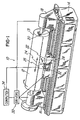
- Fig. 1 is a general perspective view of an engraver, designated generally as engraver 10.
- the engraver 10 is an intaglio engraver for engraving a cylinder 12 which will subsequently be used to print a predetermined intaglio pattern as described below.
- the cylinder 12 has a surface 13 which has an engravable coating, such as copper, similar to the type used in gravure engraving.
- the engraver 10 comprises a base 14 having a headstock 16 and tailstock 18 slidably mounted on a bed 20 situated on the base 14.
- the headstock 16 and tailstock 18 are slidably and adjustably mounted on the bed 20 with suitable bearings and drive train (not shown) such that the headstock 16 and tailstock 18 can rotatably. support the cylinder 12 therebetween.
- the engraver 10 also comprises a carriage 22 which is also slidably mounted on the bed 20 with suitable bearings and drive train (not shown).
- the carriage 22 may be driven in the direction of double arrow 24 in order to effect engraving as described below.
- the engraver 10 comprises an engraving head 26 which is slidably mounted on carriage 22 such that it can be driven towards and away from the cylinder 12 in the direction of double arrow 28 in Fig. 1.
- the engraver 10 also comprises a plurality of actuators, drive means or drivers 30 which are capable of rotatably driving the cylinder 12.
- the drivers 30 also comprise suitable motors and drive mechanisms (not shown) for selectively driving carriage 22 and engraving head 26. If desired, the drivers 30 may also comprise at least one suitable drive motor and drive train (not shown) for driving the headstock 16 and tailstock 18 into and out of engagement with the cylinder 12, thereby eliminating the need for manual adjustment.
- the drivers 30 may cause the headstock 16 and tailstock 18 to be actuated to a fully retracted position (not shown) or to a cylinder support position shown in Fig. 1.
- the drivers may be selectively energized to cause the headstock 16 and tailstock 18 to be actuated either independently or simultaneously.
- a single drive motor may be used with a single lead screw (not shown) having reversed threads (not shown) on which either end causes the headstock 16 and tailstock 18 to move simultaneously towards and away from each other as the lead screw is driven.
- Driving both the headstock 16 and tailstock 18 permits cylinders 12 of varying lengths to be loaded by an overhead crane, for example, whose path is perpendicular to the axis of rotation of the engraver 10.
- a stationary headstock 16 and tailstock 18 may be used with a driven tailstock 16 or headstock 18, respectively, if, for example, a cylinder loading mechanism (not shown) loads the cylinder 12 by moving it in a direction which is generally parallel to the axis of rotation of the engraver.
- drivers 30 may also drive a lead screw (not shown) which is coupled to the carriage 22 in order to effect driving the carriage 22 in the direction of double arrow 24.
- drivers 30 may also drive a drive train or a leadscrew which causes the engraving head 26 to move on the carriage in the direction of double arrow 28 towards and away from cylinder 12.
- the engraving head 26, carriage 22 and the driven movement thereof is similar to that shown in U. S. patent applications Serial Nos. 08/038,679; 08/022,127; 08/023,060 and 08/057,327, U. S. Patent No. 4,450,586 issued to the same assignee as the present application on May 22, 1984; U. S. Patent No.
- the engraver 10 comprises control means, a controller or a computer 34 for controlling the operation of the engraver 10, engraving head 26 and also for generating an intaglio engraving signal 38 (Fig. 10A) corresponding to the selected predetermined intaglio pattern to be engraved.
- the computer 34 also selectively controls all the drive motors, such as drivers 30 mentioned above, in the engraver 10.
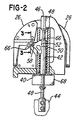
- the engraving head 26 is similar in construction and operation to the gravure engraving heads shown in one or more of the above-referenced patents, and comprises an armature 40 which is rigidly secured to a shaft 42 between opposite end portions 44 and 46 by torsional spring portions 48 of reduced diameter.
- the shaft 42 has a diameter of about 1,6 cm (0.625 inch), and the torsional spring portions each have a diameter of about 0,5 cm (0.060 inch).
- the torsional spring portions 48 and shaft portion 42 comprise a thickness diameter and weight which are selected to provide a predetermined rise time of less than approximately 100 microns.
- the predetermined response time for the engraver 10 for engraving the intaglio pattern is on the order of about 75 to 200 microseconds.
- a notch 50 is formed within the shaft portion 42 and supports an actuator arm 52 which is rigidly secured to the shaft portion 40 by a set of screws (not shown).
- a cylindrical transverse hole 54 (Fig. 4) is formed within the actuator arm 52, and an elongated rod-like holder 56 is disposed within the hole 54.
- a cutting stylus 58 preferably formed of diamond, is integrally formed or cemented into one end of the holder 56 which has a flat surface 60. The surface 60 is engaged by a set screw 62 which is threaded into a hole 64 extending outwardly from the shaft 42 through the actuator arm 52 and intersecting the hole 54.
- the actuator arm 52 is rigidly secured to the shaft 42 and projects outwardly between a pair of opposing electromagnets (not shown) which are mounted within the base portion of the engraving head 26. When the magnets (not shown) are energized the actuator arm 52 oscillates through an arc of approximately 0.25 degrees.
- guide shoe 66 is preferably formed of diamond and has a surface 68 (Fig. 3) which engages the surface of the cylinder 12 to be engraved.
- the construction and operation of the guide shoe 66 is similar to that shown in one or more of the above-referenced patents.
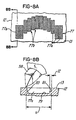
- the holder 56 in the embodiment being described has a stylus 58 which is integrally formed or secured thereto and which is generally U-shaped or bull-nosed shaped as shown.
- the stylus 58 comprises a relief angle ⁇ 1 in Fig. 7 of more than 5 degrees in one embodiment and may vary between 0 and 60 degrees, if desired. It has been found that an angle ⁇ 1 of about 20 degrees is suitable.
- stylus 58 comprises a roof angle ⁇ 2 (Fig. 7) on the order of about 60 degrees. Notice also that the tip of the stylus 58 defines a linear engaging edge or surface 58a for engaging the cylinder 12. In the embodiment being described, the width W is about 20 microns. It should be appreciated, however, that while this embodiment of the invention has been shown with a stylus having the profile and shape shown in Fig. 7, other suitable shapes may be selected depending on the cross-sectional shape of the intaglio trench to be engraved.
- the engraving head 26 is slidably located on carriage 22 and is coupled to drivers 30 and computer 34. In a manner similar to engraving heads used in gravure engravers of the past, the engraving head 26 is caused to be positioned in operative relationship with cylinder 12. At the appropriate time and in a manner described below, the computer 34 energizes engraving head 26 to engrave a desired preselected intaglio pattern or portion of an intaglio pattern, such as the picture of a portion of an actual intaglio pattern 70 shown in Fig. 8C. Notice that the intaglio engraving pattern 70 may define a substantially continuous and non-linear intaglio character 73 or a portion of the character shown in Fig.
- a character or portion 77 may be comprised of a plurality of trenches or elongated intaglio trenches 77a. These trenches 77a may be engraved such that they are continuous and connected, or they may be engraved such that one or more engraved areas or trench walls 77b are defined therebetween.
- each intaglio trench 77a is engraved to define a groove or channel having a generally planar bottom 79.
- trench 77a has a very steep forward wall 81 and rear wall 83.
- the forward wall 81 may be engraved with engraving head 26 having a response time (visually indicated by double arrows T 2 in Fig. 8B) on the order of about 100 microseconds in the embodiment being described.
- some of the intaglio trenches or channels shown in Figs. 8A and 8C, like trench 72a are generally elongated while others, like trench 72b, have a fairly short or narrow height.
- the engraver 10 is capable of engraving intaglio trenches having a cross-sectional shape as shown in Fig. 8B and having a length X (Fig. 6B) as long as desired or as short as about 0,051 mm (1/500 or 0.002 inch) for the engraving head 26 when engraving at about 500 dpi.
- Fig. 8D illustrates another character 89 which was shown engraved using a traditional gravure engraver of the type referred to above. Notice the gravure cells 91 at the top of the character, indicated by arrow 93, that gravure cells are very small and shallow. When these cells are used during actual printing, the printed image will appear non-continuous and as dots, much like the engraved cells appear in Fig. 8D.
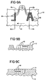
- FIG. 9A-9C Another illustration of an intaglio engraved area or trench according to one embodiment of this invention is shown in Fig. 9A-9C.
- the intaglio engraving for the letters L and A is shown.
- the stylus 58 engraves or "digs" successive trenches, such as channels, grooves or trenches 74, 76, and 78, as the cylinder 12 rotates in the direction of arrow 81 in Fig. 9A.
- the trenches 74, 76 and 78 define a generally continuous intaglio trench 83 which defines the intaglio character illustrated in Fig. 9A.
- the computer 34 comprises means for generating the intaglio engraving signal corresponding to the predetermined intaglio pattern for the letters "L" and "A".
- the signal is used to energize engraving head 26, it will effect engraving of the desired predetermined intaglio pattern 70 shown in Fig. 8. Generation of the intaglio engraving signal is described later herein.
- Figs. 10A and 10B show a partially broken-away cross-sectional illustration of two generally rectangular intaglio characters or portions of characters 86 and 88 formed from a plurality of channels or trenches engraved by the engraving head 26 in response to an intaglio engraving signal 38 as cylinder 12 rotates in the direction of arrow 82.
- This waveform signal is a pulse-width modulated signal representing or generally corresponding to the intaglio image data after modification as described herein.
- Fig. 10B is a corresponding fragmentary top view showing the trenches 86 and 88 engraved during multiple passes using signal 38 (Fig. 10A) during the rotation of the cylinder 12. Notice, again, the short rise or response time represented by the double arrow T 2 in Fig. 10B.
- the engraving response time T 2 is on the order of about 200 microseconds or about between 75 to 300 microseconds.
- a process or method by which computer 34 generates an intaglio engraving signal suitable for engraving an intaglio pattern is shown schematically.
- the computer 34 obtains source file image data or a set of data (block 90) for a character to be engraved.
- Computer 34 obtains this data from memory or it is inputted by a user via a work station or other input device (not shown). For example, data representing the character "O" in Fig. 15A would be generated or obtained by computer 34.
- a printing resolution routine (Fig. 17) described below is then performed at block 92.
- the source file image data is analyzed to determine the resolution which engraver 10 will engrave the intaglio pattern.
- the source file image data is typically supplied by computer 34 at a resolution which is greater than the engraving resolution capability of engraver 10.
- the source file image data is provided at this higher resolution in order to assure maximum image detail corresponding to the source image.
- the source image shown in Fig. 15A may be provided by computer 34 at 2000 dots per inch ("dpi"), while the engraver 10 has an engraving resolution capability of about 500 dpi in the embodiment being described. Consequently, it is necessary to modify the source file image data to a resolution that is achievable by the engraver 10 while maintaining maximum contrast in the modified source image.
- the engraving resolution it may be desirable to boost some or all of the source file image data to a minimum desired or predetermined length.
- the letter "O" has an associated minimum desired engraving height H as indicated.
- the height H is less than a predetermined length, then it may be desirable to boost or enhance the source file image data corresponding to that data height H to the appropriate height which will allow the predetermined engraving resolution to be obtained.
- the engraver 10 has a predetermined engraving resolution of about 500 dpi.
- a portion of the intaglio pattern comprises a height H which will not allow 500 dpi to be obtained, then it may be desirable to boost that portion of the source file image data in accordance with a source file boost routine (block 94 in Fig. 11).
- the source file boost routine is described later herein.
- the boosted or non-boosted source file image data is interpolated to an engraving resolution using a conventional bi-linear interpolation or image recrypting.
- a conventional bi-linear interpolation or image recrypting One suitable approach for such interpolation is described at Section 14.5, Digital Image Processing, 2nd. Ed., authored by William K. Pratt and published by John Wiley & Sons, Inc., 1991.
- the modified engraving source image data is further modified or thresholded in order to adjust the contrast in the intaglio engraving pattern (block 100) in accordance with a predetermined threshold.
- the predetermined threshold requires that those data points or pixels that represent a density of less than 50 percent of black are set to zero or white and those pixels having an associated density of more than 50 percent of black are set to black. It should be appreciated that other threshold values could be used.
- the preliminary engraving source file data is modified or thresholded to adjust for contrast, it is determined (decision block 102) whether to situate one or more ink flow controllers, such as ink flow controllers 144 in Fig. 14A, in the intaglio pattern to be engraved on cylinder 12.
- ink flow controllers such as ink flow controllers 144 in Fig. 14A
- having one or more ink flow controllers situated in the area of the predetermined intaglio pattern facilitates controlling the flow of ink during the printing process. This facilitates reducing or eliminating undesirable ink flow or capillary attraction problems when the intaglio pattern is printed.
- the ink flow controllers also facilitate providing support for a doctor blade (not shown) in a printing press (not shown).
- Fig. 14A shows a picture of a portion of an intaglio pattern 142 having a plurality of ink flow controllers 144 situated therein.
- Fig. 14B also illustrates a plurality of ink flow controllers 145 and 147 which were caused to be situated in trenches 149 and 151, respectively. Notice that a trench 153 adjacent trench 149 does not have any ink flow controllers situated therein. Notice also that the ink flow controller routine causes the ink flow controllers, such as ink flow controllers 144 (Fig. 14A) and 145 and 147 (Fig. 14B), to be staggered. This causes an ink flow controller, such as flow controller 145 in Fig. 14B to be positioned between two engraved columns or trenches like trenches 151 and 153.
- the computer 34 At the completion of the ink flow controller routine (block 104 in Fig. 11) or if the decision at decision block 102 is negative, then the computer 34 generates (block 106 in Fig. 11) a final intaglio engraving signal corresponding to the preliminary engraving source file data after it has been boosted, thresholded and adjusted.
- the computer 34 then energizes engraving head 26 (block 108) of engraver 10 to engrave the predetermined intaglio pattern, such as the engraved "O" 191 in Fig. 15C, in response to the final intaglio engraving signal at block 108 and exits when finished.
- the predetermined intaglio pattern such as the engraved "O" 191 in Fig. 15C
- the resolution routine is used.
- the resolution routine is in accordance with one embodiment of this invention is shown schematically in Fig. 17.
- computer 34 sets an INDEX to 0 at block 200.
- computer 34 inputs a finest resolution associated with the engraver 10.
- the finest resolution corresponds to the minimum black pixel run length (described below) which is to be engraved. This length depends, in turn, on such factors as inks, engraving head 26 response characteristics, printing conditions, substrates and the like. In the embodiment being described, the print resolution is on the order of about 500 dpi.
- a FINAL resolution is set equal to the source file image data resolution divided by the INDEX.
- decision block 206 it is determined whether the FINAL resolution is less than the printing resolution determined previously at block 202. If it is not, then the INDEX is incremented by a predetermined number, such as two (block 208). The routine then loops back to block 204 as shown.
- Fig. 16A illustrates a predetermined intaglio pattern that was engraved without utilizing the source file boost routine
- Fig. 16B illustrates the same engraved pattern after utilizing the source file boost routine.
- the stylus 58 did not get to a complete black depth because the height Y was shorter than the resolution (0,051 mm (1/500 inch)) of the engraving head 10 in the illustration being described. Consequently, due to the high resolution of the pattern being engraved and the associated small response time required to engrave that pattern, the engraver 10 was only capable of oscillating the stylus to a 50% black depth, indicated by dashed line 59.
- the resolution of the intaglio pattern being engraved may be finer than the response capability of the engraver. Consequently, the engraver 10 will not be capable of getting "in” and “out” of the surface 13 of the cylinder 12 quick enough to engrave fine lines or areas of the intaglio pattern. As stated above, the engraver 10 will only be capable of engraving to about 50% of a full black depth. This, in turn, causes the intaglio trenches 191 to be shallower, thinner and shorter than desired in the illustration being described. Therefore, this inhibited the ability of engraver 10 to engrave, for example, continuous intaglio trenches which define fine lines or intaglio patterns.
- the source file image data may be boosted. This facilitates ensuring that the source file image data is at a resolution which is equal to or less than the resolution capability of the engraver.
- the source file boost routine in accordance with one embodiment will now be described in relation to Fig. 12.
- the source file image data is loaded at block 110 into a buffer.
- the routine proceeds to block 114 where computer 34 determines the data length associated with data runs of one or more black pixels. Once the data length is obtained by computer 34, it is checked at decision block 116 to determine if it is less than a predetermined length. If it is less than the predetermined length, the routine proceeds to block 118 where the center of the data is calculated.
- the routine backs up approximately one-half the number of pixels in the predetermined length and then proceeds to modify the source file image data to a minimum black pixel run length.
- the minimum black pixel run length is dependent on various factors, including engraving head 26 response characteristic, printing conditions, inks, substrates and the like.
- decision block 124 it is determined if an entire column of pixels for the intaglio image being analyzed is complete (decision block 124). If not, the routine proceeds back to block 114 as shown.
- routine When the routine is complete, it exits and a modified or non-modified data file (block 126) is stored by computer 34 in suitable memory. Thereafter, the routine exits and proceeds to block 98 in Fig. 11.
- Figs. 14B and 14C shows a cross-sectional view of a plurality of ink flow controllers 147a and 147b which were caused to be situated in the engraved trench 146 to define subtrenches 146a, 146b and 146c.
- the ink flow controllers such as ink flow controller 147b in Fig. 14C, could be of a height which defines a white area when the predetermined intaglio pattern is printed.
- each ink flow controller could define a post or controller of any suitable height, width or shape which facilitates controlling undesirable turbulence and ink flow when the intaglio pattern is printed.
- ink flow controllers shown in Figs. 14A-14C represent one pixel generated by the ink controller routine described below.
- the program or ink controller routine could generate ink flow controllers 144 (Fig. 14A) having any predetermined size, height or width as desired.
- the computer 34 proceeds to the ink controller routine (block 104 in Fig. 11) which is represented schematically in Figs. 13A and 13B.
- the ink controller routine (block 104 in Fig. 11) which is represented schematically in Figs. 13A and 13B.
- computer 34 first sets a vertical offset in pixels as the OFFSET and also sets a toggle to true at block 128.
- the vertical OFFSET corresponds to the distance between adjacent ink flow controllers. In this illustration, the vertical OFFSET is constant between ink flow controllers.
- other algorithms could be utilized to space the ink flow controllers in either a non-symmetrical or symmetrical pattern.
- the computer 34 then reads the first and second columns of pixels at block 130, and at block 132, reads a third column of pixels before proceeding to a subroutine A (Fig. 13B).
- the first, second and third column of pixels correspond to adjacent columns of pixel data corresponding to a portion of the intaglio character to be engraved.
- the first, second and third columns of pixel data may generally corresponds to the engraved areas indicated by adjacent engraved areas 141a, 141b and 141c.
- the toggle is true (which it will be through the first pass through the routine)
- the INDEX is set to one-half of the OFFSET, otherwise, the INDEX is set to zero.
- the routine then proceeds to decision block 144 where the second column pixel at the INDEX location is checked to determine whether it is white or black. If it is black, then the routine proceeds to decision block 146 where it is determined whether the first column pixel at the same INDEX location is black. If the first column pixel at the INDEX location is white, then the routine proceeds to decision block 148 where it is determined whether the pixel at the INDEX location of the third column is black. If the PIXEL at the INDEX location of the first column is black at block 146, then the routine proceeds to decision block 150 where it is determined if the pixel at the INDEX location of the third column is black. If it is black or if the decision at block 148 is negative, then the second column pixel at the INDEX location is set to white.
- decision block 148 If the decision at decision block 148 is yes or if the decision at either decision block 144 or 150 is negative, then the routine proceeds to decision block 154 as shown. It is then determined whether subroutine A is complete at decision block 154, and if not, it proceeds to increment the INDEX by the OFFSET at block 156 and then again proceeds to block 144 as indicated in Fig. 13B. The routine is complete if all the columns of pixel data for that portion of the intaglio image or pattern being checked are processed.
- the routine proceeds to block 134 (Fig. 13A) where the pixels are written or stored in memory (not shown) of computer 34. If the ink controller routine has processed all columns of data (decision block 136 in Fig. 13A), then the routine exits. The routine will be complete at block 136 (Fig. 13A) if it has gone through all columns of data for a given intaglio image or pattern being engraved, such as the letter "O" in Fig. 15A. If it is not complete, then the routine proceeds to block 138 where the toggle is toggled. The routine then proceeds to block 140 where the second column of pixel data becomes the first column and the third column becomes the second column and a new third column of pixels is read (block 132).
- the final intaglio engraving signal is generated at block 106 as mentioned above.
- the final intaglio engraving signal is then used by computer 34 to energize engraving head 26 in order to effect the engraving of the predetermined intaglio pattern on cylinder 12. The engraving process and method are then complete.
- the cylinder 12 is rotatably mounted on engraver 10 between headstock 16 and tailstock 18.
- Drivers 30 rotatably drive the cylinder and the engraving head carriage 22 in rise to signals received from computer 34.
- Computer 34 also energizes drivers 30 to cause engraving head 26 to move into a start position so as to begin engraving the predetermined intaglio pattern.
- the intaglio engraving signal which generally corresponds to the predetermined intaglio pattern is generated in the manner described above.
- the computer 34 of engraver 10 then energizes the engraving head 26 to, in turn, cause the actuator arm 52 to oscillate towards and away from cylinder 12 in response to the intaglio engraving signal 38 corresponding to the predetermined intaglio pattern.
- the actuator arm 52 and stylus 58 (Fig. 4) engage the surface of the cylinder 12, at least one intaglio trench is created.
- the intaglio engraving signal may be desirable to modify the intaglio engraving signal such that at least one ink flow controller or post 144 is provided in the intaglio pattern when it is engraved in which case the ink controller routine is initiated (blocks 102 and 104 in Fig. 11). It may also be desirable as indicated above to boost a portion or all of the source file image data.
- the source file image data (illustrated in Fig 15B) is stored in memory in computer 34, or inputted into computer 34, for example, by an independent input terminal or work station (not shown).
- the source file image data is analyzed as described earlier herein and an engraving resolution is determined (block 90 in Fig. 11).
- the source file image data is again modified or thresholded as described above and a preliminary intaglio engraving signal is generated (block 94 in Fig. 11).
- An intaglio pattern such as the engraved "O" in Fig. 15C may then be engraved in response to the intaglio engraving signal.
- the intaglio process may begin.
- One or more predetermined intaglio patterns or grooves of such patterns which include one or more intaglio characters are then engraved on the surface 13 of cylinder 12.
- the cylinder 12 may be removed from the engraver 10.
- the cylinder 12 may then be rotatably mounted in a printing press (not shown).
- a web of material such as paper, plastic or the like, may then be fed through the printing press and the predetermined patterns may be printed on the web.
- this method and apparatus facilitates engraving predetermined intaglio patterns having continuous grooves or trenches on cylinders, while the cylinders are rotated.
- this intaglio engraving could be utilized with cylindrical type engravers or helical type engravers, for example, of the type that were traditionally used in gravure engraving.
- the features of this invention may be used with other types of engraving such as laser engraving.
- this apparatus and method facilitate engraving or even embossing intaglio patterns or images on a cylinder which can be engraved at speeds comparable or better than conventional gravure engravers. Also, the intaglio engraving can be performed much quicker than, for example, manual engraving of plates. Intaglio engraving in accordance with this method and apparatus is also more accurate when compared to engraving systems and methods of the past.
- this invention facilitates using a substantially or completely continuous square engraving signal which was not heretofore used in engravers which engraved intaglio patterns on cylinders for use in printing presses.
Landscapes
- Engineering & Computer Science (AREA)
- Manufacturing & Machinery (AREA)
- Mechanical Engineering (AREA)
- Multimedia (AREA)
- Signal Processing (AREA)
- Manufacture Or Reproduction Of Printing Formes (AREA)
Claims (51)
- Appareil de gravure pour graver un cylindre (12) pour l'impression d'un dessin en creux comprenant :a) des moyens d'entraínement (30) pour entraíner de façon rotative le cylindre (12) ;b) des moyens de commande (34) accouplés aux moyens d'entraínement (30) pour commander le fonctionnement de l'appareil de gravure et pour générer un signal de gravure en creux (38) correspondant au dessin en creux ;c) des moyens de gravure couplés aux moyens de commande (34) pour graver le cylindre (12) avec le dessin en creux pendant la rotation du cylindre (12) en réponse au signal de gravure en creux (38),
caractérisé en ce qued) les moyens de commande (34) sont aptes à générer le signal de gravure en creux (38) de telle sorte que le dessin en creux comprend un ou plusieurs caractères de taille en creux sensiblement continus (73) comprenant une pluralité de sillons ou de sillons allongés (77a). - Appareil de gravure selon la revendication 1, dans lequel les moyens de gravure comprennent une tête de gravure (26) avec un stylet de gravure (58).
- Appareil de gravure selon la revendication 2, dans lequel la tête de gravure (26) comprend un temps de réponse d'environ 200 microsecondes.
- Appareil de gravure selon la revendication 2, dans lequel la tête de gravure (26) comprend un temps de réponse inférieur à 200 microsecondes.
- Appareil de gravure selon l'une des revendications 2 à 4, dans lequel le stylet (58) comprend une pointe qui est de façon générale en forme de U.
- Appareil de gravure selon l'une des revendications 2 à 5, dans lequel le stylet (58) comprend un angle de dépouille supérieur à 5 degrés.
- Appareil de gravure selon la revendication 6, dans lequel l'angle de dépouille est entre environ 10 et 20 degrés.
- Appareil de gravure selon l'une des revendications 1 à 7, dans lequel les moyens de commande (34) comprennent un générateur de commande d'encre pour modifier le signal de gravure en creux (38) de telle sorte que le dessin en creux (142) comprend au moins un élément de commande d'encre (144) lorsque le dessin en creux est gravé.
- Appareil de gravure selon la revendication 8, dans lequel l'élément de commande d'encre (144) comprend un plot situé dans le dessin en creux (142).
- Appareil de gravure selon la revendication 8 ou 9, dans lequel au moins un élément de commande d'encre (144) comprend une zone non gravée (145) située dans le dessin en creux (142).
- Appareil de gravure selon l'une des revendications 8 à 10, dans lequel l'élément de commande d'encre (144) comprend une zone gravée qui est gravée à moins d'une profondeur de gravure maximum.
- Appareil de gravure selon la revendication 11, dans lequel la profondeur de gravure maximum est inférieure à environ 50 microns.
- Appareil de gravure selon l'une des revendications 8 à 12, dans lequel le signal de gravure en creux (38) comprend une première donnée de pixel, une seconde donnée de pixel et une troisième donnée de pixel, le générateur de l'élément de commande d'encre (144) comprenant de plus des moyens pour évaluer les première; seconde et troisième données de pixels et pour générer l'élément de commande d'encre (144) lorsque les première, seconde et troisième données de pixels sont noires.
- Appareil de gravure selon l'une des revendications 1 à 13, dans lequel un fichier de données source de gravure en creux correspond de façon générale à au moins une portion du dessin en creux, les moyens de commande (34) comprenant de plus des moyens d'amplification pour modifier le fichier de données source en creux pour fournir un fichier de données source en creux modifié.
- Appareil de gravure selon la revendication 14, comprenant un générateur pour générer le signal de gravure (38) en réponse au fichier de données source en creux modifié.
- Appareil de gravure selon l'une des revendications 1 à 15, dans lequel le signal de gravure en creux (38) est modulé en largeur d'impulsions.
- Appareil de gravure selon l'une des revendications 1 à 16, gravant de façon hélicoïdale le dessin en creux sur le cylindre (12).
- Appareil de gravure selon l'une des revendications 1 à 17, dans lequel le dessin en creux comprend au moins une zone ayant une hauteur de moins de 0,051 mm (0,002 pouces).
- Procédé pour la gravure d'un dessin en creux sur un cylindre (12) pour l'utilisation dans une presse d'impression pour imprimer le dessin en creux, comprenant les étapes consistant à :a) entraíner de façon rotative le cylindre (12) ;b) générer un signal de gravure en creux (38) correspondant de façon générale aux dessins en creux ;c) graver le dessin en creux sur le cylindre (12) en réponse au signal de gravure en creux (38),
caractérisé en ce qued) le signal de gravure en creux (38) est généré de telle sorte que le dessin en creux comprend un ou plusieurs caractères en creux sensiblement continus (73) en prenant une pluralité de sillons ou de sillons allongés (77a). - Procédé selon la revendication 19, dans lequel l'étape de gravure comprend de plus l'étape consistant à graver le cylindre (12) avec une tête de gravure (26) ayant un temps de réponse d'environ 200 microsecondes.
- Procédé selon la revendication 19, dans lequel l'étape de gravure comprend de plus l'étape consistant à graver le cylindre (12) avec une tête de gravure (26) ayant un temps de réponse inférieur à 200 microsecondes.
- Procédé selon l'une des revendications 19 à 21, comprenant de plus l'étape consistant à modifier le signal de gravure en creux (38) de façon qu'au moins un élément de commande d'encre (144) soit prévu dans le dessin en creux (142) lorsqu'il est gravé.
- Procédé selon la revendication 22, dans lequel au moins l'élément de commande d'encre (144) comprend une zone gravée.
- Procédé selon la revendication 22 ou 23, dans lequel au moins un élément de commande d'encre (144) comprend un sillon inférieur à la profondeur maximum.
- Procédé selon l'une des revendications 19 à 24, dans lequel le signal de gravure en creux (38) correspond de façon générale aux données de pixels associées à une pluralité de colonnes de pixels, le procédé comprenant de plus l'étape consistant à fixer au moins les données de pixels dans une de la pluralité des colonnes de pixels en non noir lorsqu'au moins un pixel contigu est noir.
- Procédé selon la revendication 25, dans lequel la pluralité de colonnes de pixels comprend une première colonne, une seconde colonne et une troisième colonne de données de pixels, l'étape de génération comprenant les étapes consistant à évaluer les première, seconde et troisième colonnes de données de pixels et à fixer la seconde colonne de données de pixels en un pixel non noir lorsque la première et la troisième colonne de données de pixels sont noires.
- Procédé selon l'une des revendications 19 à 26, comprenant de plus l'étape consistant à faire en sorte qu'au moins un élément de commande d'encre (144) soit situé dans le dessin de gravure en creux.
- Procédé selon la revendication 27, comprenant de plus l'étape consistant à faire en sorte qu'une pluralité d'éléments de commande d'encre (144) soit située dans le dessin de gravure en creux dans un dessin décalé de façon présélectionnée (144, 145, 147).
- Procédé selon la revendication 27 ou 28, dans lequel au moins l'un des éléments de commande d'encre (144) est une zone non gravée (145).
- Procédé selon la revendication 27 ou 28, dans lequel l'étape consistant à faire en sorte qu'au moins un élément de commande d'encre (144) soit situé dans le dessin de gravure en creux comprend l'étape consistant à faire en sorte qu'un élément de commande d'encre (144) inférieur à une profondeur maximum soit située dans le dessin de gravure en creux.
- Procédé selon l'une des revendications 19 à 30 comprenant de plus l'étape consistant à amplifier des données de fichier source jusqu'à une longueur prédéterminée.
- Procédé selon l'une des revendications 19 à 31, dans lequel l'étape de génération comprend l'étape consistant à générer un signal modulé en largeur d'impulsions et continu (38) pour exciter la tête de gravure (26).
- Procédé selon l'une des revendications 19 à 32, dans lequel au moins l'un de la pluralité de sillons en creux a de façon générale une coupe transversale en forme de U.
- Procédé selon l'une des revendications 19 à 33, dans lequel l'étape de gravure comprend l'étape consistant à utiliser un stylet (58) comprenant une surface de coupe généralement plate.
- Procédé selon l'une des revendications 19 à 34, dans lequel l'étape de gravure comprend l'étape consistant à utiliser un stylet (58) avec un angle de dépouille d'au moins 5 degrés.
- Procédé selon la revendication 35, dans lequel l'étape de gravure comprend l'étape consistant à utiliser un stylet (58) ayant un angle de dépouille entre 10 et 20 degrés.
- Procédé selon l'une des revendications 19 à 36, comprenant de plus l'étape consistant à graver le dessin en creux sur le cylindre (12) tandis que le cylindre est en rotation.
- Procédé selon l'une des revendications 19 à 37, comprenant de plus l'étape consistant à graver un dessin de gravure sur le cylindre (12).
- Procédé pour l'impression d'un dessin en creux en utilisant un cylindre (12) avec un dessin en creux gravé sur celui-ci, le procédé comprenant les étapes consistant à :a) monter de façon rotative un cylindre (12) dans une presse d'impression ;b) alimenter une bande continue de matériau à travers la presse d'impression ;c) imprimer le dessin en creux sur la bande continue de matériau à mesure qu'il est alimenté dans la presse ;
caractérisé en ce qued) le dessin en creux est gravé sur le cylindre de telle sorte qu'il comprend un ou plusieurs caractères en creux sensiblement continus (73) comprenant une pluralité de sillons ou de sillons allongés (77a). - Procédé selon la revendication 39, comprenant de plus l'étape consistant à utiliser un cylindre (12) qui a été gravé avec un dessin en creux tandis que le cylindre était en rotation.
- Procédé selon la revendication 39 ou 40, dans lequel la presse d'impression comprend au moins une raclette ; le procédé comprenant de plus l'étape consistant à prévoir un ou plusieurs supports de raclette situés dans le dessin en creux qui est gravé sur le cylindre (12).
- Procédé pour le perfectionnement d'un appareil de gravure pour graver un dessin en creux sur un cylindre (12) comprenant les étapes consistant à :a) mettre en oeuvre une tête de gravure (26) ayant un temps de réponse apte à graver le dessin en creux ;b) générer un signal de gravure en creux (38) basé sur le dessin en creux ;c) exciter la tête de gravure (26) avec le signal de gravure en creux (38), permettant ainsi de graver le dessin en creux.
Caractérisé en ce qued) le signal de gravure en creux (38) est généré de telle sorte que le dessin en creux comprend un ou plusieurs caractères en creux sensiblement continus (73) comprenant une pluralité de sillons ou de sillons allongés (77a). - Procédé selon la revendication 42, dans lequel le signal de gravure en creux (38) présente une forme d'onde modulée en largeur d'impulsions.
- Procédé selon la revendication 42 ou 43, dans lequel l'étape de génération comprend l'étape consistant à graver un caractère en creux continu constitué d'une pluralité de sillons en creux ayant de façon générale une section transversale en forme de U.
- Procédé selon l'une des revendications 42 à 44, dans lequel l'étape de mise en oeuvre comprend l'étape consistant à perfectionner la tête de gravure (26) de telle sorte que le temps de réponse est de l'ordre d'environ 200 microsecondes.
- Procédé selon l'une des revendications 42 à 44, dans lequel l'étape de mise en oeuvre comprend l'étape consistant à perfectionner la tête de gravure (26) de telle sorte que le temps de réponse est inférieur à 200 microsecondes.
- Procédé selon l'une des revendications 42 à 46, dans lequel l'étape d'excitation comprend l'étape consistant à graver le dessin en creux de manière hélicoïdale.
- Procédé selon l'une des revendications 42 à 47, dans lequel l'étape de génération comprend de plus l'étape consistant à générer un signal de gravure en creux (38) apte à exciter la tête de gravure (26) pour graver au moins un élément de commande d'encre (144) dans le dessin en creux (142).
- Procédé selon l'une des revendications 42 à 48, dans lequel l'étape de génération comprend de plus les étapes consistant à générer au moins une série de données de pixels correspondant au dessin en creux (142) ; analyser la série de données de pixels et à définir une zone de commande d'encre en réponse à celle-ci ; et à faire en sorte qu'au moins un élément de commande d'encre (144) soit situé dans la zone de commande d'encre.
- Procédé selon l'une des revendications 42 à 49, dans lequel l'étape de génération comprend l'étape consistant à amplifier un fichier de données source correspondant de façon générale à au moins la portion du dessin en creux.
- Procédé selon la revendication 50, comprenant de plus les étapes consistant à sélectionner un multiplicateur ; à appliquer le multiplicateur au fichier de données source pour faciliter la génération du signal de gravure en creux (38).
Applications Claiming Priority (3)
| Application Number | Priority Date | Filing Date | Title |
|---|---|---|---|
| US08/376,858 US5675420A (en) | 1995-01-23 | 1995-01-23 | Intaglio engraving method and apparatus |
| US376858 | 1995-01-23 | ||
| PCT/US1996/000656 WO1996023201A1 (fr) | 1995-01-23 | 1996-01-19 | Procede et appareil de gravure en creux |
Publications (3)
| Publication Number | Publication Date |
|---|---|
| EP0805957A1 EP0805957A1 (fr) | 1997-11-12 |
| EP0805957A4 EP0805957A4 (fr) | 1999-03-10 |
| EP0805957B1 true EP0805957B1 (fr) | 2003-07-30 |
Family
ID=23486801
Family Applications (1)
| Application Number | Title | Priority Date | Filing Date |
|---|---|---|---|
| EP96902715A Expired - Lifetime EP0805957B1 (fr) | 1995-01-23 | 1996-01-19 | Procede et appareil de gravure en creux |
Country Status (6)
| Country | Link |
|---|---|
| US (3) | US5675420A (fr) |
| EP (1) | EP0805957B1 (fr) |
| JP (1) | JP4034342B2 (fr) |
| BR (1) | BR9607175A (fr) |
| DE (1) | DE69629279T2 (fr) |
| WO (1) | WO1996023201A1 (fr) |
Families Citing this family (36)
| Publication number | Priority date | Publication date | Assignee | Title |
|---|---|---|---|---|
| US5663803A (en) * | 1993-02-25 | 1997-09-02 | Ohio Electronic Engravers, Inc. | Engraving method and apparatus for engraving areas using a shaping signal |
| US5675420A (en) * | 1995-01-23 | 1997-10-07 | Ohio Electronic Engravers, Inc. | Intaglio engraving method and apparatus |
| US6025921A (en) * | 1995-01-23 | 2000-02-15 | Ohio Electronics Engravers, Inc. | Method and apparatus for engraving a mixed pattern |
| JP3442230B2 (ja) * | 1995-12-28 | 2003-09-02 | セイコーエプソン株式会社 | 印章画像作成方法及びその装置並びに印章作成装置 |
| DE19710005A1 (de) * | 1997-03-12 | 1998-09-17 | Heidelberger Druckmasch Ag | Verfahren und Einrichtung zur Gravur von Druckzylindern |
| DE19722996A1 (de) | 1997-06-02 | 1998-12-03 | Heidelberger Druckmasch Ag | Verfahren zur Signalverarbeitung |
| US6048446A (en) * | 1997-10-24 | 2000-04-11 | R.R. Donnelley & Sons Company | Methods and apparatuses for engraving gravure cylinders |
| US5947020A (en) * | 1997-12-05 | 1999-09-07 | Ohio Electronic Engravers, Inc. | System and method for engraving a plurality of engraved areas defining different screens |
| US6563605B1 (en) | 1998-02-20 | 2003-05-13 | R. R. Donnelley & Sons Company | Methods of determining gravure cylinder parameters |
| DE19840926B4 (de) * | 1998-09-08 | 2013-07-11 | Hell Gravure Systems Gmbh & Co. Kg | Anordnung zur Materialbearbeitung mittels Laserstrahlen und deren Verwendung |
| US6433890B1 (en) | 1998-09-24 | 2002-08-13 | Mdc Max Daetwyler Ag | System and method for improving printing of a leading edge of an image in a gravure printing process |
| DE19845440A1 (de) † | 1998-10-02 | 2000-04-06 | Giesecke & Devrient Gmbh | Stichtiefdruckverfahren zum vollflächigen Bedrucken großer Flächen |
| DE19845436C5 (de) * | 1998-10-02 | 2015-02-26 | Giesecke & Devrient Gmbh | Stichtiefdruckverfahren zum Drucken von aneinander grenzenden Farbflächen unterschiedlicher Farbschichtdicke, Datenträger mit im Stichtiefdruckverfahren erzeugtem Druckbild, Druckplatte und Verfahren zum Herstellen einer Druckplatte |
| US20060249491A1 (en) * | 1999-09-01 | 2006-11-09 | Hell Gravure Systems Gmbh | Laser radiation source |
| DE19947397B4 (de) * | 1999-10-01 | 2006-12-14 | Hell Gravure Systems Gmbh | Verfahren zur nahtlosen Gravur von Mustern |
| DE19952996A1 (de) * | 1999-11-04 | 2001-05-10 | Heidelberger Druckmasch Ag | Gravierorgan für elektronische Graviermaschine |
| DE19963849A1 (de) * | 1999-12-30 | 2001-07-12 | Giesecke & Devrient Gmbh | Datenträger mit gedrucktem Sicherheitselement |
| DE10044403A1 (de) * | 2000-09-08 | 2002-03-21 | Giesecke & Devrient Gmbh | Datenträger mit Stichtiefdruckbild und Verfahren zur Umsetzung von Bildmotiven in Linienstrukturen sowie in eine Stichtiefdruckplatte |
| DE10116250A1 (de) * | 2001-03-31 | 2002-10-24 | Heidelberger Druckmasch Ag | Verfahren zur Durchführung einer Liniengravur für den Tiefdruck |
| US6779444B2 (en) * | 2001-08-01 | 2004-08-24 | Heidelberger Druckmaschinen Ag | Printing form and process for producing the printing form |
| DE10260253A1 (de) † | 2002-12-20 | 2004-07-01 | Giesecke & Devrient Gmbh | Verfahren und Vorrichtung zur Herstellung von Stichtiefdruckplatten und damit hergestellte Druckplatte |
| GB2419566A (en) * | 2003-03-14 | 2006-05-03 | Keating Gravure Systems Uk Ltd | Gravure print cylinder with engraved image decoder |
| DE10324935B4 (de) * | 2003-06-03 | 2009-11-19 | Hueck Folien Gesellschaft M.B.H. | Verfahren zur Herstellung eines Prägezylinders und die Verwendung des hergestellten Prägezylinders |
| DE10340028B4 (de) * | 2003-08-28 | 2009-07-09 | Continental Automotive Gmbh | Anzeigevorrichtung |
| US20060279793A1 (en) * | 2004-07-30 | 2006-12-14 | Hell Gravure Systems Gmbh | Printing form processing with a plurality of engraving tool tracks forming lines |
| DE102004059305A1 (de) * | 2004-12-09 | 2006-08-17 | Hueck Folien Gmbh & Co. Kg | Kupferstiche in Tiefdruckzylindern |
| EP1844929A1 (fr) | 2006-04-13 | 2007-10-17 | Kba-Giori S.A. | Procédé de génération de motifs représentant une image en demi-teintes |
| DE102007045015A1 (de) | 2007-09-20 | 2009-04-02 | Giesecke & Devrient Gmbh | Vorrichtung und Verfahren zur Erzeugung von Mehrnutzen-Stichtiefdruckplatten |
| AU2008100847A4 (en) * | 2007-10-12 | 2008-10-09 | Bluescope Steel Limited | Method of forming textured casting rolls with diamond engraving |
| US8563892B2 (en) * | 2008-09-24 | 2013-10-22 | Standex International Corporation | Method and apparatus for laser engraving |
| US9174428B2 (en) * | 2009-08-10 | 2015-11-03 | Corning Incorporated | Roll mechanics for enabling printed electronics |
| DE102010056306B4 (de) * | 2010-12-27 | 2013-07-11 | Hell Gravure Systems Gmbh & Co. Kg | Verfahren zur Gravur von Strukturen in eine Oberfläche eines Zylinders |
| US8863661B2 (en) | 2011-03-11 | 2014-10-21 | Ohio Gravure Technologies, Inc. | System and method for layer-to-layer compensation and error correction |
| US9566630B2 (en) * | 2015-07-01 | 2017-02-14 | Ball Corporation | Punch surface texturing for use in the manufacturing of metallic containers |
| CN108909158B (zh) * | 2018-08-16 | 2024-02-20 | 重庆宏劲印务有限责任公司 | 一种高速凹印防刮白版辊以及防刮白方法 |
| CN109159263A (zh) * | 2018-10-23 | 2019-01-08 | 东莞市唯美文化陶瓷有限公司 | 一种板状陶瓷图案刻画设备 |
Family Cites Families (49)
| Publication number | Priority date | Publication date | Assignee | Title |
|---|---|---|---|---|
| US2112010A (en) * | 1929-10-28 | 1938-03-22 | Brimberg Isaac | Apparatus for producing printing plates |
| US2160951A (en) * | 1935-07-05 | 1939-06-06 | Alice Francesco | Process and device for the reproduction of designs on printing plates by means of photoelectrically controlled gravers |
| US2164209A (en) * | 1935-07-25 | 1939-06-27 | Lee Electric Corp | Remote control photoelectric engraving |
| US2441651A (en) * | 1945-12-27 | 1948-05-18 | Soundscriber Corp | Phonograph recording head |
| US2575546A (en) * | 1948-07-24 | 1951-11-20 | Machine for producing screened | |
| DE930491C (de) * | 1952-07-15 | 1955-07-18 | Rudolf Dr-Ing Hell | Verfahren zur elektromechanischen Herstellung von Hochdruckformen nach Strichvorlagen |
| DE952266C (de) * | 1953-04-29 | 1956-11-15 | Hell Rudolf Dr Ing | Gravierstichel zur Herstellung gerasteter Klischees |
| CH308004A (de) * | 1954-05-14 | 1955-06-30 | Raibli Oscar | Verfahren und Maschine zur Herstellung von Facsimilé-Clichés. |
| US2881246A (en) * | 1955-09-27 | 1959-04-07 | Fairchild Camera Instr Co | Engraving machine |
| US3093071A (en) * | 1961-08-01 | 1963-06-11 | Continental Can Co | Gravure printing surface |
| NL142619B (nl) * | 1968-04-02 | 1974-07-15 | Werkspoor Amsterdam Nv | Inrichting voor het regel voor regel vervaardigen van cilindrische rasterdrukvormen met zich herhalende motieven. |
| US3636251A (en) * | 1968-08-28 | 1972-01-18 | Quantronix Corp | Laser facsimile system for engraving printing plates |
| US3652992A (en) * | 1968-11-02 | 1972-03-28 | Hell Rudolf Dr Ing | Method and apparatus for quantizing a character or test pattern preferably for the purpose of gaining control data for electronic photo composition |
| US3612753A (en) * | 1969-04-23 | 1971-10-12 | Ventures Res & Dev | Self-adaptive system for the reproduction of color |
| US3694570A (en) * | 1970-07-22 | 1972-09-26 | Evgeny Pavlovich Kotov | Automatic engraving machine |
| US3904816A (en) * | 1971-07-28 | 1975-09-09 | Hell Rudolf | Method for the dot-by-dot and line-by-line reproduction of picture originals |
| US3770888A (en) * | 1971-10-04 | 1973-11-06 | Werkspoor Amsterdam Nv | Method and apparatus for controlling the engraving pattern of an electromagnetic gravure engraving |
| US3769455A (en) * | 1972-03-01 | 1973-10-30 | Werkspoor Amsterdam Nv | Method and apparatus for making half-tone screen printing cylinders |
| US4052739A (en) * | 1972-05-19 | 1977-10-04 | Matsushita Electric Industrial Co., Ltd. | Electronic engraving system |
| US3876829A (en) * | 1973-04-20 | 1975-04-08 | Massachusetts Inst Technology | Electro-optical communication of visual images |
| CH579985A5 (fr) * | 1973-07-16 | 1976-09-30 | Hell Rudolf Dr Ing Gmbh | |
| GB1499501A (en) * | 1974-05-03 | 1978-02-01 | Crosfield Electronics Ltd | Image reproduction systems |
| US4003311A (en) * | 1975-08-13 | 1977-01-18 | Bardin Karl D | Gravure printing method |
| DE2705993C2 (de) * | 1977-02-12 | 1982-11-25 | Dr.-Ing. Rudolf Hell Gmbh, 2300 Kiel | Verfahren zum ortsgenauen Einstellen des Beginns der Abtastung bzw. Aufzeichnung einer Vorlage bei der elektronischen Druckformherstellung |
| DE2805874B2 (de) * | 1978-02-11 | 1980-08-14 | Paul 4300 Essen Pfau | Verfahren zum Herstellen einer Tiefdruckform |
| EP0007125A1 (fr) | 1978-07-10 | 1980-01-23 | Forma Glas GmbH & Co. KG | Procédé de gravure de surfaces de verre et de meulage de corps de verre et dispositif pour la réalisation du procédé |
| US4301583A (en) * | 1979-02-15 | 1981-11-24 | Consolidated Engravers Corporation | Fluid metering roller |
| US4394693A (en) * | 1979-03-23 | 1983-07-19 | International Business Machines Corporation | System and method for generating enlarged or reduced images |
| US4450486A (en) * | 1979-07-11 | 1984-05-22 | Ohio Electronic Engravers, Inc. | Engraving apparatus and method |
| US4357633A (en) * | 1979-07-11 | 1982-11-02 | Buechler Lester W | Engraving apparatus and method |
| US4500929A (en) * | 1979-07-11 | 1985-02-19 | Buechler Lester W | Method of engraving an invisible joint within a gravure printing cylinder |
| US4451856A (en) * | 1979-07-11 | 1984-05-29 | Ohio Electronic Engravers, Inc. | Engraving and scanning apparatus |
| DE3139483C2 (de) * | 1981-10-03 | 1985-06-13 | Dr.-Ing. Rudolf Hell Gmbh, 2300 Kiel | Verfahren und Schaltungsanordnung zur Kontraststeigerung |
| US4503468A (en) * | 1981-10-09 | 1985-03-05 | Northern Telecom Limited | Interactive viewgraph system |
| GB2150788B (en) * | 1983-06-03 | 1987-07-22 | Gravure Res Inst | Screen gravure engraving system for electomechanical engravers |
| DE3425626A1 (de) * | 1984-07-12 | 1986-01-16 | Dr.-Ing. Rudolf Hell Gmbh, 2300 Kiel | Verfahren zur herstellung von druckzylindern fuer nahtlos- bzw. endlosmuster mittels druckform-graviermaschinen |
| JPS6238658A (ja) | 1985-08-14 | 1987-02-19 | Hitachi Ltd | 副走査速度の制御方法 |
| DE3619320C1 (de) * | 1986-06-09 | 1987-03-05 | Daetwyler Ag | Gravierkopf fuer ein Geraet zum Gravieren von Tiefdruckzylindern und aehnlichen Druckformen |
| CH672458A5 (fr) * | 1986-10-02 | 1989-11-30 | Daetwyler Ag | |
| JPH01237140A (ja) | 1988-03-18 | 1989-09-21 | Hitachi Ltd | 記録装置 |
| WO1990014230A1 (fr) * | 1989-05-24 | 1990-11-29 | Dai Nippon Insatsu Kabushiki Kaisha | Appareil electronique de photogravure |
| US5293426A (en) * | 1990-05-25 | 1994-03-08 | R. R. Donnelley & Sons Company | Printing cylinder engraver calibration system and method |
| DE59106977D1 (de) * | 1990-09-04 | 1996-01-11 | Daetwyler Ag | Verfahren zum Bearbeiten von Tiefdruckformen. |
| US5138118A (en) * | 1991-05-06 | 1992-08-11 | International Business Machines Corporation | Pulsed pen for use with a digitizer tablet |
| JP2736598B2 (ja) * | 1992-09-14 | 1998-04-02 | 大日本スクリーン製造株式会社 | エンドレスパターン製版方法及び装置 |
| US5424845A (en) * | 1993-02-25 | 1995-06-13 | Ohio Electronic Engravers, Inc. | Apparatus and method for engraving a gravure printing cylinder |
| US5438422A (en) * | 1993-02-25 | 1995-08-01 | Ohio Electronic Engravers, Inc. | Error detection apparatus and method for use with engravers |
| US5519502A (en) * | 1994-04-06 | 1996-05-21 | Ohio Electronic Engravers, Inc. | Method and apparatus for selectively linearizing cells in an engraver |
| US5675420A (en) * | 1995-01-23 | 1997-10-07 | Ohio Electronic Engravers, Inc. | Intaglio engraving method and apparatus |
-
1995
- 1995-01-23 US US08/376,858 patent/US5675420A/en not_active Expired - Fee Related
-
1996
- 1996-01-19 EP EP96902715A patent/EP0805957B1/fr not_active Expired - Lifetime
- 1996-01-19 DE DE69629279T patent/DE69629279T2/de not_active Expired - Lifetime
- 1996-01-19 JP JP52292696A patent/JP4034342B2/ja not_active Expired - Fee Related
- 1996-01-19 WO PCT/US1996/000656 patent/WO1996023201A1/fr active IP Right Grant
- 1996-01-19 BR BR9607175A patent/BR9607175A/pt not_active Application Discontinuation
-
1997
- 1997-07-01 US US08/886,488 patent/US5892589A/en not_active Expired - Fee Related
-
1999
- 1999-04-02 US US09/285,128 patent/US6525839B1/en not_active Expired - Fee Related
Also Published As
| Publication number | Publication date |
|---|---|
| EP0805957A4 (fr) | 1999-03-10 |
| BR9607175A (pt) | 1997-11-11 |
| US6525839B1 (en) | 2003-02-25 |
| WO1996023201A1 (fr) | 1996-08-01 |
| US5675420A (en) | 1997-10-07 |
| US5892589A (en) | 1999-04-06 |
| EP0805957A1 (fr) | 1997-11-12 |
| DE69629279D1 (de) | 2003-09-04 |
| DE69629279T2 (de) | 2004-05-27 |
| JP4034342B2 (ja) | 2008-01-16 |
| JPH11500070A (ja) | 1999-01-06 |
Similar Documents
| Publication | Publication Date | Title |
|---|---|---|
| EP0805957B1 (fr) | Procede et appareil de gravure en creux | |
| WO1996023201A9 (fr) | Procede et appareil de gravure en creux | |
| US6840721B2 (en) | Process for producing dies | |
| RU2308379C2 (ru) | Способ изготовления гравированной пластины | |
| WO1999033660A1 (fr) | Systeme de gravure et procede faisant appel a differents dispositifs de gravure | |
| EP2414175B1 (fr) | Plaque d'impression en relief, procédé et appareil de fabrication de plaque d'impression | |
| US6025921A (en) | Method and apparatus for engraving a mixed pattern | |
| US5691818A (en) | System and method for enhancing edges and the like for engraving | |
| EP0671260B1 (fr) | Procédé de gravure d'un cylindre gravé | |
| WO2014157291A1 (fr) | Procédé de réalisation de plaque, dispositif de réalisation de plaque, procédé d'impression et plaque d'impression | |
| GB2303094A (en) | Laser engraved ceramic gravure cylinder | |
| EP1367812B1 (fr) | Procédé et dispositif permettant l'élimination des raccords dans des données d'images tramées pour l'impression en continue | |
| DE19815165B4 (de) | Verfahren zur Gravur von Druckformen | |
| JP4582977B2 (ja) | 最適化されたイメージ処理の方法及び装置 | |
| US20040008383A1 (en) | Method and apparatus for eliminating seams in screened image data for repetitive printing | |
| Bennett et al. | The Zedcotm Rubber Roller Engraving Machine | |
| SU153725A1 (fr) | ||
| CN1169773A (zh) | 凹版雕刻的方法和设备 | |
| US20060152770A1 (en) | Gravure printing | |
| JPH06143533A (ja) | グラビア製版出力装置 | |
| JPH09286092A (ja) | グラビア彫刻システム |
Legal Events
| Date | Code | Title | Description |
|---|---|---|---|
| PUAI | Public reference made under article 153(3) epc to a published international application that has entered the european phase |
Free format text: ORIGINAL CODE: 0009012 |
|
| 17P | Request for examination filed |
Effective date: 19970319 |
|
| AK | Designated contracting states |
Kind code of ref document: A1 Designated state(s): CH DE LI |
|
| A4 | Supplementary search report drawn up and despatched |
Effective date: 19990125 |
|
| AK | Designated contracting states |
Kind code of ref document: A4 Designated state(s): CH DE LI |
|
| RAP1 | Party data changed (applicant data changed or rights of an application transferred) |
Owner name: MDC MAX DAETWYLER AG BLEIENBACH |
|
| 17Q | First examination report despatched |
Effective date: 20011017 |
|
| GRAH | Despatch of communication of intention to grant a patent |
Free format text: ORIGINAL CODE: EPIDOS IGRA |
|
| GRAH | Despatch of communication of intention to grant a patent |
Free format text: ORIGINAL CODE: EPIDOS IGRA |
|
| GRAA | (expected) grant |
Free format text: ORIGINAL CODE: 0009210 |
|
| AK | Designated contracting states |
Designated state(s): CH DE LI |
|
| REG | Reference to a national code |
Ref country code: CH Ref legal event code: EP |
|
| REG | Reference to a national code |
Ref country code: CH Ref legal event code: NV Representative=s name: KATZAROV S.A. |
|
| REF | Corresponds to: |
Ref document number: 69629279 Country of ref document: DE Date of ref document: 20030904 Kind code of ref document: P |
|
| PG25 | Lapsed in a contracting state [announced via postgrant information from national office to epo] |
Ref country code: LI Free format text: LAPSE BECAUSE OF NON-PAYMENT OF DUE FEES Effective date: 20040131 Ref country code: CH Free format text: LAPSE BECAUSE OF NON-PAYMENT OF DUE FEES Effective date: 20040131 |
|
| PLBE | No opposition filed within time limit |
Free format text: ORIGINAL CODE: 0009261 |
|
| STAA | Information on the status of an ep patent application or granted ep patent |
Free format text: STATUS: NO OPPOSITION FILED WITHIN TIME LIMIT |
|
| 26N | No opposition filed |
Effective date: 20040504 |
|
| REG | Reference to a national code |
Ref country code: CH Ref legal event code: PL |
|
| PGFP | Annual fee paid to national office [announced via postgrant information from national office to epo] |
Ref country code: DE Payment date: 20110304 Year of fee payment: 16 |
|
| PG25 | Lapsed in a contracting state [announced via postgrant information from national office to epo] |
Ref country code: DE Free format text: LAPSE BECAUSE OF NON-PAYMENT OF DUE FEES Effective date: 20120801 |
|
| REG | Reference to a national code |
Ref country code: DE Ref legal event code: R119 Ref document number: 69629279 Country of ref document: DE Effective date: 20120801 |