EP0805941B1 - Machine de production de chaleur et de froid - Google Patents
Machine de production de chaleur et de froid Download PDFInfo
- Publication number
- EP0805941B1 EP0805941B1 EP96900320A EP96900320A EP0805941B1 EP 0805941 B1 EP0805941 B1 EP 0805941B1 EP 96900320 A EP96900320 A EP 96900320A EP 96900320 A EP96900320 A EP 96900320A EP 0805941 B1 EP0805941 B1 EP 0805941B1
- Authority
- EP
- European Patent Office
- Prior art keywords
- heat exchanger
- cold
- regenerator
- bypass
- heating
- Prior art date
- Legal status (The legal status is an assumption and is not a legal conclusion. Google has not performed a legal analysis and makes no representation as to the accuracy of the status listed.)
- Expired - Lifetime
Links
- 238000000034 method Methods 0.000 claims abstract description 21
- 230000001172 regenerating effect Effects 0.000 claims abstract description 9
- 238000010438 heat treatment Methods 0.000 claims description 14
- 238000007710 freezing Methods 0.000 abstract description 12
- 230000008014 freezing Effects 0.000 abstract description 12
- 238000001816 cooling Methods 0.000 description 9
- 238000005482 strain hardening Methods 0.000 description 6
- 238000002485 combustion reaction Methods 0.000 description 2
- 230000006378 damage Effects 0.000 description 2
- 230000000694 effects Effects 0.000 description 2
- 238000004378 air conditioning Methods 0.000 description 1
- 230000005540 biological transmission Effects 0.000 description 1
- 230000015572 biosynthetic process Effects 0.000 description 1
- 238000010276 construction Methods 0.000 description 1
- 238000005516 engineering process Methods 0.000 description 1
- 239000000284 extract Substances 0.000 description 1
- 230000002631 hypothermal effect Effects 0.000 description 1
- 230000007257 malfunction Effects 0.000 description 1
- 230000001360 synchronised effect Effects 0.000 description 1
Images
Classifications
-
- F—MECHANICAL ENGINEERING; LIGHTING; HEATING; WEAPONS; BLASTING
- F25—REFRIGERATION OR COOLING; COMBINED HEATING AND REFRIGERATION SYSTEMS; HEAT PUMP SYSTEMS; MANUFACTURE OR STORAGE OF ICE; LIQUEFACTION SOLIDIFICATION OF GASES
- F25B—REFRIGERATION MACHINES, PLANTS OR SYSTEMS; COMBINED HEATING AND REFRIGERATION SYSTEMS; HEAT PUMP SYSTEMS
- F25B9/00—Compression machines, plants or systems, in which the refrigerant is air or other gas of low boiling point
- F25B9/14—Compression machines, plants or systems, in which the refrigerant is air or other gas of low boiling point characterised by the cycle used, e.g. Stirling cycle
-
- F—MECHANICAL ENGINEERING; LIGHTING; HEATING; WEAPONS; BLASTING
- F25—REFRIGERATION OR COOLING; COMBINED HEATING AND REFRIGERATION SYSTEMS; HEAT PUMP SYSTEMS; MANUFACTURE OR STORAGE OF ICE; LIQUEFACTION SOLIDIFICATION OF GASES
- F25B—REFRIGERATION MACHINES, PLANTS OR SYSTEMS; COMBINED HEATING AND REFRIGERATION SYSTEMS; HEAT PUMP SYSTEMS
- F25B9/00—Compression machines, plants or systems, in which the refrigerant is air or other gas of low boiling point
Definitions
- the invention relates to a working according to a regenerative gas cycle process Heating and cooling machine with at least two pistons, the minimum three process rooms, each with at least one heat exchanger and at least one regenerator connected in series with this separate from each other.
- the invention has for its object one after a regenerative gas cycle process to create working heating and cooling machine in which the Risk of freezing of the cold heat exchanger with design and control technology is simply eliminated in an energetically meaningful manner.
- the solution to this problem by the invention is characterized in that that at least one of the cold process room assigned Regenerators to change the cold heat exchange circuit amount of heat transferred between process gas and environment with at least a bypass containing a control valve is provided.
- the inventive formation of a bypass to at least one of the regenerators assigned to the cold heat exchanger is activated the bypass valve of icing on the air heat exchanger is limited in time opened so that the process gas in this bypassed bypass Regenerator no heat is removed and in this way the in the machine arranged cold heat exchangers through the from the warm process room amount of heat coming to a temperature above freezing is brought, with which the air heat exchanger is de-iced at the same time. Also in the event of a failure of the circulation pump in the one belonging to the cold heat exchanger In this way, the cycle becomes active even when the machine is running freezing of the cold heat exchanger avoided.
- the bypass line is in Formed a through opening in the regenerator, the two Ends are closed during normal operation of the machine. This results in a dead space-free design of this regenerator.
- bypass line is passed through closed a plunger, which is countered by an electromagnet Force of a return spring is movable.
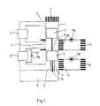
- the heating and cooling machine shown schematically in Figure 1 includes a pressure-tight housing 1, in which a hot piston 2 and a cold piston 3 are arranged linearly movable.
- the hot piston 2 limits a hot working volume 4, to which heat is supplied, for example by a gas-heated one Combustion chamber 5.
- the cold piston 3 limits a cold working volume 6.
- Both pistons 2 and 3 limit a warm working volume 7.
- a gear 8 is provided, which is connected to the cold via a hollow piston rod 9 Piston 3 and another piston rod 10 with the hot piston 2 connected is.
- a regenerator 11 or 12 is arranged.
- the warm working volume 7 is also assigned a warm heat exchanger 14, which is connected in series with the regenerator 11 and as well this is flowed through by the process gas. From this warm heat exchanger 13 is heated in the closed circuit via a circulation pump 13a a heat exchanger designed as a heater 14, for example.
- the cold working volume 6 is also in series with the regenerator 12 assigned cold heat exchanger 15 through which process gas flows, the one with an air heat exchanger 16 in a closed circuit is arranged.
- a circulation pump 15a is located in this circuit.
- the heating and cooling machine is the one assigned to the cold working volume 6
- Regenerator 12 is provided with a bypass 17, in which a bypass valve 17a is arranged. In normal operation, this bypass valve 17a is closed, see above that the bypass 17 has no effect on the after a regenerative gas cycle process working heating and cooling machine.
- the bypass valve is also to be eliminated if the circulation pump 15a fails 17a opened at least for a limited time.
- the process gas is due the lower flow resistance, the regenerator 12 through the Bypass bypass 17 so that the process gas in the regenerator 12 no heat is withdrawn. Since the cold heat exchanger 15 is connected in series to the regenerator 12 is switched, the cold heat exchanger 15 by the from the warm Working volume 7 coming amount of heat at a temperature above the Freezing point brought or held.
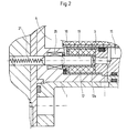
- FIG. 2 shows an embodiment of the regenerator 12 in one Longitudinal section.
- the regenerator 12 stands with the cold working volume 6 of the machine via an annular channel 18 and is in series switched to the cold heat exchanger 15, part of which is also in Figure 2 is shown.
- the part of the regenerator 12 shown in FIG. 2 is further provided with a through hole 12a through a plunger 19 is closable. In the closed position, the plunger 19 fills the through opening 12a of regenerator 12 acting as a bypass, see above that there is no dead space in the normal operation of the machine due to the bypass.
Landscapes
- Engineering & Computer Science (AREA)
- Physics & Mathematics (AREA)
- Mechanical Engineering (AREA)
- Thermal Sciences (AREA)
- General Engineering & Computer Science (AREA)
- Sorption Type Refrigeration Machines (AREA)
- Engine Equipment That Uses Special Cycles (AREA)
- Fluid-Pressure Circuits (AREA)
- Devices That Are Associated With Refrigeration Equipment (AREA)
- Compressors, Vaccum Pumps And Other Relevant Systems (AREA)
- Compressor (AREA)
Claims (3)
- Machine de production de chaleur et de froid fonctionnant selon un cycle à gaz à récupération, avec au moins deux pistons (2, 3), qui séparent les unes des autres au moins trois chambres (4, 6, 7) avec interposition respectivement d'au moins un échangeur de chaleur (13, 15)et d'au moins un récupérateur (11, 12) monté en série avec ceux-ci,
caractérisée en ce que
l'un au moins des récupérateurs (12) associés à la chambre froide (6) du procédé est pourvue au moins d'une dérivation (17), qui contient une vanne de commande (17a), pour modifier la quantité de chaleur qui est transmise par l'intermédiaire du circuit de l'échangeur de chaleur froid entre le gaz du procédé et l'environnement. - Machine de production de chaleur et de froid selon la revendication 1,
caractérisée en ce que
la conduite de dérivation (17) est constituée sous la forme d'une ouverture de passage (12a) dans le récupérateur (12), cette ouverture étant fermée aux deux extrémités quand la machine fonctionne normalement. - Machine de production de chaleur et de froid selon la revendication 1 ou 2,
caractérisée en ce que
la conduite de dérivation (17) peut être fermée par un piston plongeur (19), qui peut être déplacé au moyen d'un électroaimant (20) à l'encontre de la force d'un ressort de rappel (21).
Applications Claiming Priority (3)
| Application Number | Priority Date | Filing Date | Title |
|---|---|---|---|
| DE19502190 | 1995-01-25 | ||
| DE19502190A DE19502190C2 (de) | 1995-01-25 | 1995-01-25 | Wärme- und Kältemaschine |
| PCT/EP1996/000134 WO1996023182A1 (fr) | 1995-01-25 | 1996-01-13 | Machine de production de chaleur et de froid |
Publications (2)
| Publication Number | Publication Date |
|---|---|
| EP0805941A1 EP0805941A1 (fr) | 1997-11-12 |
| EP0805941B1 true EP0805941B1 (fr) | 1999-11-03 |
Family
ID=7752259
Family Applications (1)
| Application Number | Title | Priority Date | Filing Date |
|---|---|---|---|
| EP96900320A Expired - Lifetime EP0805941B1 (fr) | 1995-01-25 | 1996-01-13 | Machine de production de chaleur et de froid |
Country Status (8)
| Country | Link |
|---|---|
| US (1) | US6029449A (fr) |
| EP (1) | EP0805941B1 (fr) |
| JP (1) | JPH11503511A (fr) |
| KR (1) | KR19980701775A (fr) |
| AT (1) | ATE186391T1 (fr) |
| DE (2) | DE19502190C2 (fr) |
| ES (1) | ES2139327T3 (fr) |
| WO (1) | WO1996023182A1 (fr) |
Families Citing this family (6)
| Publication number | Priority date | Publication date | Assignee | Title |
|---|---|---|---|---|
| DE19746838A1 (de) * | 1997-10-23 | 1999-04-29 | Bosch Gmbh Robert | Verfahren und Vorrichtung zum Betreiben einer nach einem regenerativen Gaskreisprozeß arbeitenden Wärme- und Kältemaschine |
| JPH11193967A (ja) * | 1997-12-26 | 1999-07-21 | Zexel:Kk | 冷凍サイクル |
| KR20070012305A (ko) * | 2003-07-01 | 2007-01-25 | 티악스 엘엘씨 | 외연엔진에 사용되는 레큐퍼레이터 및 연소기, 및 이것을사용한 동력발생 시스템 |
| DE102008009782A1 (de) * | 2008-02-19 | 2009-08-27 | BSH Bosch und Siemens Hausgeräte GmbH | Hausgerät zum Trocknen eines feuchten Gutes mit einer Kühlanordnung und einer Heizanordnung |
| DE102009023968A1 (de) * | 2009-06-05 | 2010-12-09 | Danfoss Compressors Gmbh | Verdrängereinheit einer Stirling-Kühleinrichtung und Stirling-Kühleinrichtung |
| US20170167759A1 (en) * | 2014-02-22 | 2017-06-15 | Thermolift, Inc. | A Thermally-Driven Heat Pump Having a Heat Exchanger Located Between Displacers |
Family Cites Families (6)
| Publication number | Priority date | Publication date | Assignee | Title |
|---|---|---|---|---|
| US1275507A (en) * | 1917-01-29 | 1918-08-13 | Rudolph Vuilleumier | Method and apparatus for inducing heat changes. |
| NL7000001A (fr) * | 1970-01-02 | 1971-07-06 | ||
| DE2156773C3 (de) * | 1971-11-16 | 1974-09-19 | Motoren Werke Mannheim Ag | Verfahren zur lastabhängigen Regelung der Leistung eines doppeltwirkenden Heißgasmotors |
| DE3536710A1 (de) * | 1985-10-15 | 1987-04-23 | Schneider Christian Dipl Ing | Waermewandler und verfahren zu seinem betrieb |
| US5400599A (en) * | 1991-12-09 | 1995-03-28 | Sanyo Electric Co., Ltd. | Hot gas machine |
| JPH06101922A (ja) * | 1992-09-17 | 1994-04-12 | Daikin Ind Ltd | ビルマイヤヒートポンプ装置 |
-
1995
- 1995-01-25 DE DE19502190A patent/DE19502190C2/de not_active Expired - Fee Related
-
1996
- 1996-01-13 US US08/860,211 patent/US6029449A/en not_active Expired - Fee Related
- 1996-01-13 DE DE59603564T patent/DE59603564D1/de not_active Expired - Fee Related
- 1996-01-13 AT AT96900320T patent/ATE186391T1/de not_active IP Right Cessation
- 1996-01-13 KR KR1019970705172A patent/KR19980701775A/ko not_active Abandoned
- 1996-01-13 EP EP96900320A patent/EP0805941B1/fr not_active Expired - Lifetime
- 1996-01-13 ES ES96900320T patent/ES2139327T3/es not_active Expired - Lifetime
- 1996-01-13 WO PCT/EP1996/000134 patent/WO1996023182A1/fr not_active Ceased
- 1996-01-13 JP JP8522582A patent/JPH11503511A/ja active Pending
Also Published As
| Publication number | Publication date |
|---|---|
| WO1996023182A1 (fr) | 1996-08-01 |
| ES2139327T3 (es) | 2000-02-01 |
| ATE186391T1 (de) | 1999-11-15 |
| EP0805941A1 (fr) | 1997-11-12 |
| JPH11503511A (ja) | 1999-03-26 |
| KR19980701775A (ko) | 1998-06-25 |
| DE19502190C2 (de) | 1998-03-19 |
| US6029449A (en) | 2000-02-29 |
| DE19502190A1 (de) | 1996-08-01 |
| DE59603564D1 (de) | 1999-12-09 |
Similar Documents
| Publication | Publication Date | Title |
|---|---|---|
| EP0945291B1 (fr) | Dispositif et procédé pour chauffer et réfrigérer l'espace de chargement d'un véhicule | |
| DE10123830A1 (de) | Klimaanlage | |
| DE60018751T2 (de) | Kühlschrank oder gefrierschrank mit luftstromregelung | |
| EP0216237A2 (fr) | Accumulateur à sorption à marche discontinue avec un absorbeur contenant un solide | |
| DE3907859C2 (de) | Luftgekühltes Kälteaggregat mit einem Kühlmittelkreislauf | |
| DE102014106725A1 (de) | Antriebsstrangkühlsystem mit kühl- und heizmodi für wärmetauscher | |
| EP0805941B1 (fr) | Machine de production de chaleur et de froid | |
| EP2321592B1 (fr) | Pompe à chaleur ou machine frigorifique et procédé permettant de faire fonctionner une pompe à chaleur ou une machine frigorifique | |
| DE2826430A1 (de) | Fahrgastraumheiz- und -klimatisiersystem fuer kraftfahrzeuge mit einem motorkuehlsystem mit niedriger kuehlmitteltemperatur | |
| DE10313850B4 (de) | Kältemittelkreislauf mit zweistufiger Verdichtung für einen kombinierten Kälteanlagen- und Wärmepumpenbetrieb, insbesondere für Kraftfahrzeuge | |
| DE2923621A1 (de) | Thermischer antrieb | |
| DE3313371A1 (de) | Tieftemperatur-kaeltemaschine | |
| DE69120376T2 (de) | Kühlsystem | |
| DE102007047642B4 (de) | Kältemaschine | |
| DE69611717T2 (de) | Vuillermier Freikolbenmaschine | |
| DE102009030041A1 (de) | Fahrzeug-Klimasystem | |
| WO2003064194A1 (fr) | Installation de climatisation | |
| DE102019105505B4 (de) | Kühlmittelkreislauf in einem Fahrzeug | |
| DE19913154A1 (de) | Taumelscheiben-Stirlingkühler | |
| DE1501098A1 (de) | Anlage zum Erzeugen von Kaelte bei niedrigen Temperaturen und zur Anwendung in dieser Anlage gut geeignete Kaltgas-Kuehlmaschine | |
| DE2422150C3 (de) | Heißgaskolbenmaschine mit einer Vorrichtung zur Regelung der Gewichtsmenge des in einem Arbeitsraum vorhandenen Arbeitsmediums | |
| DE1751420A1 (de) | Kombinierter Kuehlschrank | |
| DE102018002120A1 (de) | Einrichtung zum Temperieren von durch Filtern gereinigten flüssigen Mediums | |
| DE2309337C3 (de) | Anfahrregelung für Kaltdampfkältemaschinen | |
| DE1002568B (de) | Heissluftmaschine |
Legal Events
| Date | Code | Title | Description |
|---|---|---|---|
| PUAI | Public reference made under article 153(3) epc to a published international application that has entered the european phase |
Free format text: ORIGINAL CODE: 0009012 |
|
| 17P | Request for examination filed |
Effective date: 19970825 |
|
| AK | Designated contracting states |
Kind code of ref document: A1 Designated state(s): AT CH DE ES FR GB IT LI NL |
|
| GRAG | Despatch of communication of intention to grant |
Free format text: ORIGINAL CODE: EPIDOS AGRA |
|
| 17Q | First examination report despatched |
Effective date: 19990129 |
|
| GRAG | Despatch of communication of intention to grant |
Free format text: ORIGINAL CODE: EPIDOS AGRA |
|
| GRAH | Despatch of communication of intention to grant a patent |
Free format text: ORIGINAL CODE: EPIDOS IGRA |
|
| GRAH | Despatch of communication of intention to grant a patent |
Free format text: ORIGINAL CODE: EPIDOS IGRA |
|
| GRAA | (expected) grant |
Free format text: ORIGINAL CODE: 0009210 |
|
| AK | Designated contracting states |
Kind code of ref document: B1 Designated state(s): AT CH DE ES FR GB IT LI NL |
|
| REF | Corresponds to: |
Ref document number: 186391 Country of ref document: AT Date of ref document: 19991115 Kind code of ref document: T |
|
| REG | Reference to a national code |
Ref country code: CH Ref legal event code: NV Representative=s name: SCINTILLA AG, DIREKTION Ref country code: CH Ref legal event code: EP |
|
| REF | Corresponds to: |
Ref document number: 59603564 Country of ref document: DE Date of ref document: 19991209 |
|
| ET | Fr: translation filed | ||
| ITF | It: translation for a ep patent filed | ||
| REG | Reference to a national code |
Ref country code: ES Ref legal event code: FG2A Ref document number: 2139327 Country of ref document: ES Kind code of ref document: T3 |
|
| GBT | Gb: translation of ep patent filed (gb section 77(6)(a)/1977) |
Effective date: 20000113 |
|
| PLBE | No opposition filed within time limit |
Free format text: ORIGINAL CODE: 0009261 |
|
| STAA | Information on the status of an ep patent application or granted ep patent |
Free format text: STATUS: NO OPPOSITION FILED WITHIN TIME LIMIT |
|
| 26N | No opposition filed | ||
| REG | Reference to a national code |
Ref country code: GB Ref legal event code: IF02 |
|
| PGFP | Annual fee paid to national office [announced via postgrant information from national office to epo] |
Ref country code: FR Payment date: 20030117 Year of fee payment: 8 |
|
| PGFP | Annual fee paid to national office [announced via postgrant information from national office to epo] |
Ref country code: NL Payment date: 20030121 Year of fee payment: 8 Ref country code: AT Payment date: 20030121 Year of fee payment: 8 |
|
| PGFP | Annual fee paid to national office [announced via postgrant information from national office to epo] |
Ref country code: ES Payment date: 20030123 Year of fee payment: 8 |
|
| PGFP | Annual fee paid to national office [announced via postgrant information from national office to epo] |
Ref country code: CH Payment date: 20030124 Year of fee payment: 8 |
|
| PGFP | Annual fee paid to national office [announced via postgrant information from national office to epo] |
Ref country code: DE Payment date: 20030225 Year of fee payment: 8 |
|
| PGFP | Annual fee paid to national office [announced via postgrant information from national office to epo] |
Ref country code: GB Payment date: 20031231 Year of fee payment: 9 |
|
| PG25 | Lapsed in a contracting state [announced via postgrant information from national office to epo] |
Ref country code: AT Free format text: LAPSE BECAUSE OF NON-PAYMENT OF DUE FEES Effective date: 20040113 |
|
| PG25 | Lapsed in a contracting state [announced via postgrant information from national office to epo] |
Ref country code: ES Free format text: LAPSE BECAUSE OF NON-PAYMENT OF DUE FEES Effective date: 20040114 |
|
| PG25 | Lapsed in a contracting state [announced via postgrant information from national office to epo] |
Ref country code: LI Free format text: LAPSE BECAUSE OF NON-PAYMENT OF DUE FEES Effective date: 20040131 Ref country code: CH Free format text: LAPSE BECAUSE OF NON-PAYMENT OF DUE FEES Effective date: 20040131 |
|
| PG25 | Lapsed in a contracting state [announced via postgrant information from national office to epo] |
Ref country code: NL Free format text: LAPSE BECAUSE OF NON-PAYMENT OF DUE FEES Effective date: 20040801 |
|
| PG25 | Lapsed in a contracting state [announced via postgrant information from national office to epo] |
Ref country code: DE Free format text: LAPSE BECAUSE OF NON-PAYMENT OF DUE FEES Effective date: 20040803 |
|
| REG | Reference to a national code |
Ref country code: CH Ref legal event code: PL |
|
| PG25 | Lapsed in a contracting state [announced via postgrant information from national office to epo] |
Ref country code: FR Free format text: LAPSE BECAUSE OF NON-PAYMENT OF DUE FEES Effective date: 20040930 |
|
| NLV4 | Nl: lapsed or anulled due to non-payment of the annual fee |
Effective date: 20040801 |
|
| REG | Reference to a national code |
Ref country code: FR Ref legal event code: ST |
|
| PG25 | Lapsed in a contracting state [announced via postgrant information from national office to epo] |
Ref country code: IT Free format text: LAPSE BECAUSE OF NON-PAYMENT OF DUE FEES Effective date: 20050113 Ref country code: GB Free format text: LAPSE BECAUSE OF NON-PAYMENT OF DUE FEES Effective date: 20050113 |
|
| REG | Reference to a national code |
Ref country code: ES Ref legal event code: FD2A Effective date: 20040114 |
|
| GBPC | Gb: european patent ceased through non-payment of renewal fee |
Effective date: 20050113 |