EP0805584A2 - Bilderzeuger mit virtueller, innen aufzeichnender Trommel und Kapstan-Antrieb - Google Patents
Bilderzeuger mit virtueller, innen aufzeichnender Trommel und Kapstan-Antrieb Download PDFInfo
- Publication number
- EP0805584A2 EP0805584A2 EP97102689A EP97102689A EP0805584A2 EP 0805584 A2 EP0805584 A2 EP 0805584A2 EP 97102689 A EP97102689 A EP 97102689A EP 97102689 A EP97102689 A EP 97102689A EP 0805584 A2 EP0805584 A2 EP 0805584A2
- Authority
- EP
- European Patent Office
- Prior art keywords
- media
- recording
- virtual drum
- scanning
- drum
- Prior art date
- Legal status (The legal status is an assumption and is not a legal conclusion. Google has not performed a legal analysis and makes no representation as to the accuracy of the status listed.)
- Granted
Links
Images

Classifications
-
- H—ELECTRICITY
- H04—ELECTRIC COMMUNICATION TECHNIQUE
- H04N—PICTORIAL COMMUNICATION, e.g. TELEVISION
- H04N1/00—Scanning, transmission or reproduction of documents or the like, e.g. facsimile transmission; Details thereof
- H04N1/04—Scanning arrangements, i.e. arrangements for the displacement of active reading or reproducing elements relative to the original or reproducing medium, or vice versa
- H04N1/06—Scanning arrangements, i.e. arrangements for the displacement of active reading or reproducing elements relative to the original or reproducing medium, or vice versa using cylindrical picture-bearing surfaces, i.e. scanning a main-scanning line substantially perpendicular to the axis and lying in a curved cylindrical surface
- H04N1/0607—Scanning a concave surface, e.g. with internal drum type scanners
- H04N1/0621—Scanning a concave surface, e.g. with internal drum type scanners using a picture-bearing surface stationary in the main-scanning direction
- H04N1/0635—Scanning a concave surface, e.g. with internal drum type scanners using a picture-bearing surface stationary in the main-scanning direction using oscillating or rotating mirrors
-
- H—ELECTRICITY
- H04—ELECTRIC COMMUNICATION TECHNIQUE
- H04N—PICTORIAL COMMUNICATION, e.g. TELEVISION
- H04N1/00—Scanning, transmission or reproduction of documents or the like, e.g. facsimile transmission; Details thereof
- H04N1/04—Scanning arrangements, i.e. arrangements for the displacement of active reading or reproducing elements relative to the original or reproducing medium, or vice versa
- H04N1/06—Scanning arrangements, i.e. arrangements for the displacement of active reading or reproducing elements relative to the original or reproducing medium, or vice versa using cylindrical picture-bearing surfaces, i.e. scanning a main-scanning line substantially perpendicular to the axis and lying in a curved cylindrical surface
- H04N1/0607—Scanning a concave surface, e.g. with internal drum type scanners
-
- H—ELECTRICITY
- H04—ELECTRIC COMMUNICATION TECHNIQUE
- H04N—PICTORIAL COMMUNICATION, e.g. TELEVISION
- H04N1/00—Scanning, transmission or reproduction of documents or the like, e.g. facsimile transmission; Details thereof
- H04N1/04—Scanning arrangements, i.e. arrangements for the displacement of active reading or reproducing elements relative to the original or reproducing medium, or vice versa
- H04N1/06—Scanning arrangements, i.e. arrangements for the displacement of active reading or reproducing elements relative to the original or reproducing medium, or vice versa using cylindrical picture-bearing surfaces, i.e. scanning a main-scanning line substantially perpendicular to the axis and lying in a curved cylindrical surface
- H04N1/0664—Scanning arrangements, i.e. arrangements for the displacement of active reading or reproducing elements relative to the original or reproducing medium, or vice versa using cylindrical picture-bearing surfaces, i.e. scanning a main-scanning line substantially perpendicular to the axis and lying in a curved cylindrical surface with sub-scanning by translational movement of the picture-bearing surface
Definitions
- Imagesetting and platesetting devices are available in flatbed, internal drum, external drum, and capstan-type engine configurations. Each configuration offers varying features and benefits, depending on the demands of the user.
- the user's demands such as image quality and resolution, printing run length, and work flow volume or output speed can determine the best configuration for the job.
- the recording media is in a web form and has a continuous motion through the device so that imaging occurs without delays for media loading and unloading.
- an advantage is realized because of the symmetry of the internal drum, in a relatively simple and inexpensive optical system compared to an optical system in a capstan system.
- Typical capstan systems require an expensive F-theta lens to a allow the scanned beam to be focused across the flat scan line.
- disadvantages may be associated with each type of output device.
- a large and expensive drum for an internal drum system is cast of aluminum and requires precision machining on the drum surface.
- Some internal and external drum systems require expensive vacuum systems to keep the media stationary against the drum during imaging. Delays in imaging can occur frequently due to loading and unloading sheet form recording media.
- the floor space generally required by an internal drum imagesetter is large.
- the present invention provides a method and apparatus for recording an image onto a web-type image recording media.
- the invention comprises a media transport system for transporting web-type image recording media through the imaging system and a media imaging station for recording an image onto the media.
- the media imaging station includes a curved support which supports the media and forms the media into a virtual drum.
- the media imaging station includes a scanning mechanism for scanning a modulated image recording beam across the virtual drum in a scan line.
- the media transport system transports the media relative to the curved support during scanning by the scanning mechanism to form a series of adjacent scan lines.
- the present invention further provides an electronic prepress apparatus/method including a computer workstation for creating, previewing, storing and transferring electronic image files to be outputted onto recording media.
- the workstation controls other components of the electronic prepress system, which can include an image processor for converting the electronic image files transferred from the computer workstation into digital data files.
- An output device for outputting the digital data files onto recording media in a form of images previewed on said computer means, includes a media transport mechanism for transporting recording media along a media path, a curved support for supporting the media and forming the media into a virtual drum having an axis parallel to the media path, and a scanning apparatus for scanning a modulated recording beam representing the digital data files across the virtual drum in a scan line.
- a capstan driven virtual internal drum imaging system is shown, generally indicated as 10, according to the present invention.
- the imaging system 10 has a media supply station 12, a media tensioning station 14, an imaging station 16, a capstan drive 18, a media cutter 20, and a media take-up station 22.
- Web type image recording media 24 is used in the imaging system 10 and can be paper, film, or plate type material.
- the media supply station 12 contains a supply roll of the media 24 which is supported on a roll shaft 28 which has a drive gear 30 on the outer end of the shaft 28.
- the drive gear 30 is driven by a motor 32 which rotates the drive gear 30 through a motor gear 34 connected to the motor shaft 36.
- the media 24 is fed through the tensioning station 14 which includes a series of rollers 38, 40, 42, which rotate freely about their respective roller shafts 44, 46, 48.
- a tensioning spring 50 is connected to the shaft 46 of roller 40.
- Roller 40 is vertically adjustable relative to the other rollers 38, 42 and relative to a support frame (not shown) to accommodate and control slack or tension in the media 24.
- the tensioning station 14 works in cooperation with the drive motor 32 during start and stop sequences to control the media and absorb torque disturbances.
- the spring has a tension measuring gauge to measure the tension or slack in the media. The gauge provides feedback to the media supply drive motor 32 to control the output torque of the drive motor 32 according to the amount of tension in the media.
- the imaging station 16 includes a curved media platen 52 which has an upper surface 54 and a lower surface 56 between which the media 24 passes.
- a space 57 is provided between the upper and lower surfaces 54, 56 for the media 24, the space being a few mils thicker than the thickness of the media 24.
- the curved media platen 52 can be provided with a mechanism to adjust the space 57 between the upper and lower surfaces 54, 56, such as with a precision screw and nut assembly on the outer ends of the platen (not shown), to accommodate varying thicknesses of media 24.
- the lower surface 56 is provided with a slot 58 through which the media 24 is imaged.
- the media 24 is curved by the platen 52 creating a radius of curvature R in the media with a center of curvature C to form a virtual drum for optimal imaging according to the present invention.
- the curved media platen 52 is shown having a relatively narrow width in the preferred embodiment of the invention.
- the width of the platen 52 in the direction of the media motion can be larger, and that the curvature of the media platen need not be uniform over the width of the platen.
- the platen can have a very large radius of curvature at the entrance and exit of the media plate so as to be flat at the entrance and exit, and to have a relatively small radius of curvature at the center of the media plate at the area of the media plate to form the virtual drum in the media where the media is imaged, and having smooth transitional areas between the entrance, center, and exit of the media platen to allow smooth passing of the media through the platen without rippling of the media.
- several narrow media platens may be spaced apart along the media path. In all these variations the virtual drum is formed in the media.
- a laser scanning system 60 is positioned below the curved media platen 52.
- a laser source 62 generates a beam 64 which is focused by an optical element 66 onto a reflective spinner 68.
- the spinner 68 is rotated by spin motor 70 to scan the reflected beam 72 across the virtual drum of the media 24 through slot 58 of the lower surface 56 of the media platen 52 in a scanline.
- the center of curvature C of the virtual drum is the same point that the beam 64 encounters the reflective spinner 68.
- the distance the beam travels from the spinner to the media at the slot is uniform during rotation of the spinner through an angle during which the beam scans the media.
- the beam spot focus remains uniform as a result.
- the laser source 62 is modulated on and off by an acoustic-optical modulator 74, hereinafter AOM.
- AOM acoustic-optical modulator
- the media motion is continuous during beam scanning to write successive lines of half-tone dots onto the media to form a continuous image.
- Motion of the media is primarily controlled by the capstan drive 18.
- the capstan drive 18 has a pair of nip rollers 76, 78 which are driven by drive motor 80. The nip rollers are pinched together in rolling contact so that motion is transmitted from the driven roller 76 to the other roller 78 upon its rotation.
- the capstan drive 18 accurately controls the media motion to synchronize the advancement of the media 24 though the imaging station 16 with the laser scanning system 60 in the following manner.
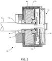
- an integrated rotary drive apparatus 100 is shown as the preferred embodiment for a connection between the drive motor 80 and nip roller shaft 82 of the capstan drive 18.
- the integrated rotary drive apparatus 100 has a closed loop electronic feedback controller which varies the torque output from the motor 80 for the purpose of rotating the nip roller 76 in a controlled manner.
- the nip roller shaft 82 is supported within a hollow shaft 102 of the motor 80 supported by bearings 104, 106.
- the bearings are contained within a motor case 108.
- an inertia flywheel 110 and a rotary optical encoder disk 112 which rotate with the hollow shaft 102 and with the nip roller shaft 82.
- the roller shaft 82 is mechanically coupled to the hollow shaft 102 as well as to the motor armature assembly, generally shown as 114.
- An optical encoder reader 116 is also contained and fixed within the casing 108.
- the optical encoder disk 112 when aligned with encoder reader 116 provides electrical feedback to a closed loop electronic control system.
- the feedback comprises an electronic signal representative of the angular position and velocity of hollow shaft 200.
- the feedback signal is used to control the output torque of the DC motor 80 to provide motion control of the nip roller 76. Additional details of the integrated rotary drive apparatus are provided in U.S. Patent 5,450,770, which is hereby incorporated by reference.
- the tensioning station 14 and the capstan drive 18 are important to the invention to keep the media 24 taught during media motion through the curved media platen 52.
- the tensioning system 14 provides a force pulling the media tight in the reverse direction of the media motion, to the left as viewed in Fig. 1, while the Capstan drive motor 80 and nip rollers 76, 78 provide a force pulling the media to the right as viewed in Fig. 1.
- This allows for the media 24 to smoothly transition from a flat profile at the rollers 42 and 76, 78, to the curved profile in the media platen 52 with a radius of curvature R, without rippling of the media in the areas between the rollers and the platen 52.
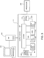
- an electronic prepress system 200 is depicted showing the output device 10 according to the present invention in connection with a workstation 202, a raster image processor (RIP) 204, and an on-line processor 206.
- the workstation 202 is used to create, store, preview and transfer electronic files of images, and to control other components of the electronic prepress system 200.
- the workstation transfers the electronic files to the RIP 204 for digitizing, i.e. converting the electronic files into digital images which can be understood by the output device 10 and sent through the AOM 74 for output.
- the output device 10 has a controller 220 which controls the commands and signals to the supply drive motor 32, the spin motor 68, and the capstan drive motor 80.
- a feedback loop 222 is shown from the media tension sensor 224 to the controller 220 which provides feedback to the supply drive motor 32 to control the output torque of the drive motor 32 according to the amount of tension in the media.
- the controller 220 synchronizes the control of the spin motor 68 and the AOM 74, as indicated by loop 226.
- the closed loop electronic control system 228 is shown for the integrated rotary drive apparatus 100, as previously described, wherein the optical encoder 116 provides feedback to the controller 220 to control the output torque of the capstan drive motor 80.
- Information is exchanged between the RIP 204 and the output device 10, as well as between the output device 10 and the processor 206.
- the media 24 is moved past the media cutter 20 and into the take-up station 22.
- a take-up cassette 82 collects the media 24.
- the media cutter can be selectively activated by an operator or it can be controlled by the output device controller 220, to cut the media between jobs or accumulate successive jobs and cut when the cassette is full.
- the take-up station may comprise an on-line processing device 206, as depicted in Fig. 3 , when the media outputted from the present invention requires additional processing, whether it be chemical "wet processing or mechanical dry type processing.
- curved media platen described with reference to Fig. 1 curves the media into a partial cylinder having a uniform radius of curvature.
- configuration of the media platen may be other than that described herein and the optical system may be designed to accommodate such other configurations to obtain accurate and focused imaging on the media.
Landscapes
- Engineering & Computer Science (AREA)
- Multimedia (AREA)
- Signal Processing (AREA)
- Exposure And Positioning Against Photoresist Photosensitive Materials (AREA)
- Handling Of Sheets (AREA)
- Projection-Type Copiers In General (AREA)
- Paper Feeding For Electrophotography (AREA)
- Facsimile Scanning Arrangements (AREA)
- Printers Or Recording Devices Using Electromagnetic And Radiation Means (AREA)
- Electrophotography Using Other Than Carlson'S Method (AREA)
Applications Claiming Priority (4)
| Application Number | Priority Date | Filing Date | Title |
|---|---|---|---|
| US640308 | 1996-04-30 | ||
| US08/640,308 US5850248A (en) | 1996-04-30 | 1996-04-30 | Capstan driven virtual internal drum imagesetter |
| US08/640,048 US5835686A (en) | 1996-04-30 | 1996-04-30 | Electronic prepress system having a capstan driven virtual internal drum imagesetter |
| US640048 | 1996-04-30 |
Publications (3)
| Publication Number | Publication Date |
|---|---|
| EP0805584A2 true EP0805584A2 (de) | 1997-11-05 |
| EP0805584A3 EP0805584A3 (de) | 1998-04-01 |
| EP0805584B1 EP0805584B1 (de) | 2001-09-12 |
Family
ID=27093468
Family Applications (1)
| Application Number | Title | Priority Date | Filing Date |
|---|---|---|---|
| EP19970102689 Expired - Lifetime EP0805584B1 (de) | 1996-04-30 | 1997-02-19 | Bilderzeuger mit virtueller, innen aufzeichnender Trommel und Kapstan-Antrieb |
Country Status (3)
| Country | Link |
|---|---|
| EP (1) | EP0805584B1 (de) |
| JP (1) | JPH1093775A (de) |
| DE (1) | DE69706600T2 (de) |
Cited By (1)
| Publication number | Priority date | Publication date | Assignee | Title |
|---|---|---|---|---|
| EP0878955A3 (de) * | 1997-05-16 | 1999-09-22 | HK Productions Limited | Vorrichtung zur Bewegung eines Strahlungsbündels über ein Medium |
Family Cites Families (4)
| Publication number | Priority date | Publication date | Assignee | Title |
|---|---|---|---|---|
| NL26337C (de) * | 1928-03-26 | |||
| US3809806A (en) * | 1972-10-18 | 1974-05-07 | Columbia Broadcasting Syst Inc | Banding correction system for film recording apparatus |
| DE3318311A1 (de) * | 1983-05-19 | 1984-11-22 | Dr. Böger Photosatz GmbH, 2000 Wedel | Optische lichtfleck-abtastvorrichtung fuer ein photoempfindliches bahnmaterial bei optischen photosetzgeraeten |
| US4635108A (en) * | 1983-09-09 | 1987-01-06 | 501 Hazeltine Corporation | Scanner-previewer combination including a programmable sampling circuit for permitting an entire frame of an original to be stored in a fixed-capacity memory |
-
1997
- 1997-02-19 DE DE1997606600 patent/DE69706600T2/de not_active Expired - Fee Related
- 1997-02-19 EP EP19970102689 patent/EP0805584B1/de not_active Expired - Lifetime
- 1997-04-10 JP JP9106803A patent/JPH1093775A/ja active Pending
Cited By (1)
| Publication number | Priority date | Publication date | Assignee | Title |
|---|---|---|---|---|
| EP0878955A3 (de) * | 1997-05-16 | 1999-09-22 | HK Productions Limited | Vorrichtung zur Bewegung eines Strahlungsbündels über ein Medium |
Also Published As
| Publication number | Publication date |
|---|---|
| DE69706600D1 (de) | 2001-10-18 |
| EP0805584B1 (de) | 2001-09-12 |
| DE69706600T2 (de) | 2002-06-06 |
| JPH1093775A (ja) | 1998-04-10 |
| EP0805584A3 (de) | 1998-04-01 |
Similar Documents
| Publication | Publication Date | Title |
|---|---|---|
| US4967233A (en) | Fixed full width array scan head calibration apparatus | |
| FI84543B (fi) | Gruppobservationssystem. | |
| JP2000025996A (ja) | 画像プリント | |
| US6238113B1 (en) | Media feed apparatus for imaging system | |
| US5850248A (en) | Capstan driven virtual internal drum imagesetter | |
| EP1261193A1 (de) | Vorrichtung und Verfahren zur Steuerung des Lesens einer weissen Referenzplatte in einem Bildlesegerät mit Einziehvorrichtung | |
| CN1400562A (zh) | 原稿扫描装置 | |
| EP0805584B1 (de) | Bilderzeuger mit virtueller, innen aufzeichnender Trommel und Kapstan-Antrieb | |
| US5835686A (en) | Electronic prepress system having a capstan driven virtual internal drum imagesetter | |
| US5050858A (en) | Sheet feed control method | |
| US5894342A (en) | Imagesetter | |
| EP1024404A1 (de) | Verfahren und Vorrichtung zur Pufferübertragung von Blätter zwischen Komponenten in einem Bildaufzeichnungssystem | |
| JP4300912B2 (ja) | 記録媒体搬送装置及び画像記録装置 | |
| US5663554A (en) | Weak lens focus adjusting mechanism based upon thickness of scanned material and imagesetter using same | |
| JP3493726B2 (ja) | レーザ光走査装置 | |
| US20030205639A1 (en) | Method and apparatus for buffer transfer of media sheets between components in an imaging system | |
| JP2872261B2 (ja) | 複写装置 | |
| JPH03172069A (ja) | 画像入力装置における走査キャリッジ運動制御装置および方法 | |
| JP2832030B2 (ja) | 複写装置 | |
| JP3202891B2 (ja) | 記録装置 | |
| JP2579536B2 (ja) | 感材ガイド機構 | |
| JP2649960B2 (ja) | 媒体ガイド機構 | |
| JP2899118B2 (ja) | シート材搬送装置 | |
| JP2000343773A (ja) | 記録装置のプラテン機構 | |
| JPH03227847A (ja) | 記録装置 |
Legal Events
| Date | Code | Title | Description |
|---|---|---|---|
| PUAI | Public reference made under article 153(3) epc to a published international application that has entered the european phase |
Free format text: ORIGINAL CODE: 0009012 |
|
| AK | Designated contracting states |
Kind code of ref document: A2 Designated state(s): BE DE FR GB |
|
| PUAL | Search report despatched |
Free format text: ORIGINAL CODE: 0009013 |
|
| AK | Designated contracting states |
Kind code of ref document: A3 Designated state(s): BE DE FR GB |
|
| 17P | Request for examination filed |
Effective date: 19980806 |
|
| RAP1 | Party data changed (applicant data changed or rights of an application transferred) |
Owner name: AGFA CORPORATION |
|
| 17Q | First examination report despatched |
Effective date: 19991117 |
|
| GRAG | Despatch of communication of intention to grant |
Free format text: ORIGINAL CODE: EPIDOS AGRA |
|
| GRAG | Despatch of communication of intention to grant |
Free format text: ORIGINAL CODE: EPIDOS AGRA |
|
| GRAH | Despatch of communication of intention to grant a patent |
Free format text: ORIGINAL CODE: EPIDOS IGRA |
|
| GRAG | Despatch of communication of intention to grant |
Free format text: ORIGINAL CODE: EPIDOS AGRA |
|
| GRAH | Despatch of communication of intention to grant a patent |
Free format text: ORIGINAL CODE: EPIDOS IGRA |
|
| GRAH | Despatch of communication of intention to grant a patent |
Free format text: ORIGINAL CODE: EPIDOS IGRA |
|
| GRAA | (expected) grant |
Free format text: ORIGINAL CODE: 0009210 |
|
| AK | Designated contracting states |
Kind code of ref document: B1 Designated state(s): BE DE FR GB |
|
| PG25 | Lapsed in a contracting state [announced via postgrant information from national office to epo] |
Ref country code: BE Free format text: LAPSE BECAUSE OF FAILURE TO SUBMIT A TRANSLATION OF THE DESCRIPTION OR TO PAY THE FEE WITHIN THE PRESCRIBED TIME-LIMIT Effective date: 20010912 |
|
| REF | Corresponds to: |
Ref document number: 69706600 Country of ref document: DE Date of ref document: 20011018 |
|
| REG | Reference to a national code |
Ref country code: GB Ref legal event code: IF02 |
|
| ET | Fr: translation filed | ||
| PLBE | No opposition filed within time limit |
Free format text: ORIGINAL CODE: 0009261 |
|
| STAA | Information on the status of an ep patent application or granted ep patent |
Free format text: STATUS: NO OPPOSITION FILED WITHIN TIME LIMIT |
|
| 26N | No opposition filed | ||
| PGFP | Annual fee paid to national office [announced via postgrant information from national office to epo] |
Ref country code: FR Payment date: 20021210 Year of fee payment: 7 |
|
| PGFP | Annual fee paid to national office [announced via postgrant information from national office to epo] |
Ref country code: DE Payment date: 20021212 Year of fee payment: 7 |
|
| PGFP | Annual fee paid to national office [announced via postgrant information from national office to epo] |
Ref country code: GB Payment date: 20021216 Year of fee payment: 7 |
|
| PG25 | Lapsed in a contracting state [announced via postgrant information from national office to epo] |
Ref country code: GB Free format text: LAPSE BECAUSE OF NON-PAYMENT OF DUE FEES Effective date: 20040219 |
|
| PG25 | Lapsed in a contracting state [announced via postgrant information from national office to epo] |
Ref country code: DE Free format text: LAPSE BECAUSE OF NON-PAYMENT OF DUE FEES Effective date: 20040901 |
|
| GBPC | Gb: european patent ceased through non-payment of renewal fee |
Effective date: 20040219 |
|
| PG25 | Lapsed in a contracting state [announced via postgrant information from national office to epo] |
Ref country code: FR Free format text: LAPSE BECAUSE OF NON-PAYMENT OF DUE FEES Effective date: 20041029 |
|
| REG | Reference to a national code |
Ref country code: FR Ref legal event code: ST |