EP0805538B1 - Überstrom- und Kurzschlusssicherung - Google Patents
Überstrom- und Kurzschlusssicherung Download PDFInfo
- Publication number
- EP0805538B1 EP0805538B1 EP97106689A EP97106689A EP0805538B1 EP 0805538 B1 EP0805538 B1 EP 0805538B1 EP 97106689 A EP97106689 A EP 97106689A EP 97106689 A EP97106689 A EP 97106689A EP 0805538 B1 EP0805538 B1 EP 0805538B1
- Authority
- EP
- European Patent Office
- Prior art keywords
- current
- circuit
- values
- short
- overcurrent
- Prior art date
- Legal status (The legal status is an assumption and is not a legal conclusion. Google has not performed a legal analysis and makes no representation as to the accuracy of the status listed.)
- Expired - Lifetime
Links
- 239000004065 semiconductor Substances 0.000 claims abstract description 12
- 238000012545 processing Methods 0.000 claims description 3
- 238000003860 storage Methods 0.000 claims 2
- 230000001934 delay Effects 0.000 claims 1
- 230000014759 maintenance of location Effects 0.000 claims 1
- 238000002360 preparation method Methods 0.000 claims 1
- 238000012544 monitoring process Methods 0.000 description 10
- 238000001514 detection method Methods 0.000 description 4
- 239000008186 active pharmaceutical agent Substances 0.000 description 3
- 238000010586 diagram Methods 0.000 description 3
- 238000011156 evaluation Methods 0.000 description 3
- 238000000034 method Methods 0.000 description 3
- 230000001419 dependent effect Effects 0.000 description 2
- 230000006378 damage Effects 0.000 description 1
- 238000011161 development Methods 0.000 description 1
- 230000018109 developmental process Effects 0.000 description 1
- 230000000694 effects Effects 0.000 description 1
- 238000004904 shortening Methods 0.000 description 1
Images

Classifications
-
- H—ELECTRICITY
- H02—GENERATION; CONVERSION OR DISTRIBUTION OF ELECTRIC POWER
- H02H—EMERGENCY PROTECTIVE CIRCUIT ARRANGEMENTS
- H02H7/00—Emergency protective circuit arrangements specially adapted for specific types of electric machines or apparatus or for sectionalised protection of cable or line systems, and effecting automatic switching in the event of an undesired change from normal working conditions
- H02H7/10—Emergency protective circuit arrangements specially adapted for specific types of electric machines or apparatus or for sectionalised protection of cable or line systems, and effecting automatic switching in the event of an undesired change from normal working conditions for converters; for rectifiers
- H02H7/12—Emergency protective circuit arrangements specially adapted for specific types of electric machines or apparatus or for sectionalised protection of cable or line systems, and effecting automatic switching in the event of an undesired change from normal working conditions for converters; for rectifiers for static converters or rectifiers
- H02H7/122—Emergency protective circuit arrangements specially adapted for specific types of electric machines or apparatus or for sectionalised protection of cable or line systems, and effecting automatic switching in the event of an undesired change from normal working conditions for converters; for rectifiers for static converters or rectifiers for inverters, i.e. DC/AC converters
- H02H7/1227—Emergency protective circuit arrangements specially adapted for specific types of electric machines or apparatus or for sectionalised protection of cable or line systems, and effecting automatic switching in the event of an undesired change from normal working conditions for converters; for rectifiers for static converters or rectifiers for inverters, i.e. DC/AC converters responsive to abnormalities in the output circuit, e.g. short circuit
Definitions
- the invention describes an overcurrent and short-circuit protection for power semiconductor circuit arrangements according to the features of the preamble of claim 1. It will the example of one built with IGBT or MOS power semiconductor components Inverter circuit explained.
- the overcurrent protection device is described in DE 42 42 560 A1. Here is at the same time a device for detecting an overcurrent is shown.
- the overcurrent detection device consists of a switching element with a control electrode and others Components for detecting a current flowing in the switching element. Such According to the information given there, the device protects the freewheeling diodes from occurring Overflowing.
- V CE monitoring is used in IGBT circuit structures and V DS monitoring in MOS transistor structures for short-circuit protection.
- the principle of operation of both methods is basically the same. Both monitoring methods represent a considerable amount of circuitry and are usually strongly temperature-dependent. The cost-intensive protection is limited to the event of a short circuit, and any overcurrent that has to be detected must be detected by a separate overcurrent monitor.
- the saturation voltage is strongly temperature-dependent, at a temperature ⁇ 1 the maximum voltage drop U max is reached at constant current and at a temperature ⁇ 2 the minimum value U min .
- the absolute values of ⁇ 1 and ⁇ 2 depend on the technology of the circuit breaker (6), ⁇ 1 can be both larger and smaller ⁇ 2 .
- the switch-off threshold (11), a voltage proportional to the maximum permissible transistor current, must be dimensioned, e.g. for an IGBT with a reverse voltage rating of 1200 volts approx. 5 volts, that the voltage drop (8, 9) U max (resulting from the permitted current) not yet at ⁇ 1 ), but exceeding the maximum current as an error signal (14) at temperature ⁇ 2 leads to the gate voltage (15) being switched off safely.
- the monitoring after the switch-on signal for a so-called blanking time be deactivated, otherwise an overcurrent is detected during switch-on.
- the switch-off threshold is therefore not exceeded until there is a time delay for example, a delay of 100 ns at a voltage of 500V. During this time the Monitoring be hidden, otherwise an overcurrent would be incorrectly detected.
- the current through the circuit breaker also increases with a finite slope, in the case a short circuit, for example with 1000A / ⁇ s, which leads to an increase in the Current amplitude of 100A would lead, which in turn has the effect shown by the Current flow-related overvoltage amplified.
- the short-circuit protection according to the prior art is because of the strong Temperature dependence of the saturation voltage is not at the same time an overcurrent protection that must be made possible by additional actual value monitoring.
- the actual current values required for control in converters are transmitted via current transducers, so-called current sensors detected.
- the actual current value can, for example, be one for current proportional voltage.
- the current sensor evaluations have precise shutdown waves, which, however, experience a time slip due to their processing in superimposed systems, whereby too long periods of time for switching off, for example with IGBT of approx. 10 ⁇ s, lapse to effectively protect the circuitry from short circuits.
- V CE or V DS monitoring (13) in FIG. 1 which is customary in the prior art, is complex and must be implemented for each individual power semiconductor component (6). Due to the dead time, the overcurrent monitoring can only be used as overcurrent protection, but not as short-circuit protection. In practice according to the state of the art, both safety measures, V CE and current monitoring, are used in combination, which results in the high cost share.
- EP-A-0.490.388 discloses an earth fault protection for current rectification, current actual values being detected at each of the n phases of alternating current outputs and all individual values being compared with threshold values, the outputs of all comparators being combined via an OR gate.
- the present invention has set itself the task of having an economical converter Overcurrent and short circuit protection for IGBT and MOSFET power circuitry in the form of overcurrent limitation for reliable protection of the Display arrangement before earth faults and overcurrents with little additional effort.
- Fig. 2 shows the schematic diagram of the invention.
- the switching signals are given to the circuit breaker (6) via the driver (3).
- the current sensors (7) installed in the phases on the load side pass on all actual values to window comparators (2), which emit an error signal when the maximum value is exceeded.
- the errors are summed in the error memory (1).
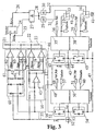
- Fig. 3 explains the circuit for protecting the power part of a circuit arrangement with several half bridges, consisting of a lower (45, 54) and an upper (42, 51) circuit breaker.
- the circuit breakers can be both IGBT and MOSFET.
- a current detector 43, 52
- a current sensor which is already used for the higher-level control and must therefore have a high level of basic accuracy and a low temperature dependence.
- the control signals (36, 39, 49, 51) of the superimposed control are via suitable Driver stages (35, 38, 48, 50) led to the control inputs of the power semiconductor switch.
- the driver stages can be blocked via the inputs TopEnable (37) and BotEnable (40) become. If there are no such inputs, the individual control signals Separated from the driver stages (35, 38, 48, 50) via switches.
- the actual values obtained from the existing current transducers are used for protection (55, 56) of the n outputs of the power section used.
- the reference mass (41) of the measured values is electrically isolated from those of the outputs (44, 53). Furthermore, the reference mass (41) be separated from the positive (46) and the negative (47) DC link voltage, this is but not absolutely necessary.
- the actual current values (55, 56) are converted using a n-fold bridge rectifier (60) the positive (62) and negative (65) maximum Instantaneous values determined and by a window comparator (61) with the positive (63) and the negative (64) maximum amplitudes.
- the actual current values (55, 56) are reduced to one Summation amplifier (16) performed.
- the sum of all output currents (18) is calculated using a further window comparators (17) on exceeding or falling below the maximum (19) or minimum (20) threshold controlled.
- the outputs (23) of all window comparators (61, 17) are connected via a wired or (22) or another OR operation on the set input of an error memory (24).
- the "Error” (26) output signal can be reset using the "Reset” (25) signal.
- the error memory can also be implemented with a monostable time stage no reset signal required.
- the output (28) of the AND link (27) is connected via the delay elements td1 (29) or td2 (30) to the control inputs of the switches (33) and (34).
- the time delay In any case, td1 (29) is not equal to the time delay td2 (39). In the time when no Error signal (26) and no reset signal (25) is set, the switches (33 and 34) closed, the control of the power semiconductor switch then lies with the controller.
- the switches (33 and 34) are opened with a time delay and the circuit breakers (42, 45, 51, 54) blocked by the driver stages (35, 38, 48, 50).
- the state of the control signals from the controller no longer has any influence.
- the time delay of all components of the Protection circuit takes place in any case within the time that everyone Power semiconductor switch survives non-destructively.
Landscapes
- Engineering & Computer Science (AREA)
- Power Engineering (AREA)
- Emergency Protection Circuit Devices (AREA)
- Protection Of Static Devices (AREA)
- Inverter Devices (AREA)
- Testing Of Short-Circuits, Discontinuities, Leakage, Or Incorrect Line Connections (AREA)
Description
- Fig. 1
- stellt in Skizze den relevanten Teil einer Schaltung nach dem Stand der Technik dar, wie er bereits auf vorgehenden Seiten erläutert wurde.
- Fig. 2
- stellt die Prinzipskizze der Erfindung dar.
- Fig. 3
- veranschaulicht einen Schaltungsast mit dem erfinderischen Schutz des Leistungsteiles einer Treiberschaltung.
Claims (6)
- Steuereinrichtung zur Überstrom- und Kurzschlußsicherung für Leistungshalbleiter-Schaltungsanordnungen mit Stromdetektoreinrichtungen, Vergleichseinrichtungen, Signalgeneratoreinrichtungen und einer Einrichtung zum Unterbrechen des Betriebes der Halbleiterbauelemente
dadurch gekennzeichnet, daß
Stromistwerte an jeder der n Phasen eines Umrichterleistungsteiles an Wechselstromausgängen erfaßt und in zwei parallelen Einrichtungen verarbeitet werden, wobei in der ersten Einrichtung (16, 17) ein Summenstrom gebildet und mit einem Schwellwert verglichen wird und in der zweiten Einrichtung (60, 61) der maximale positive und negative Augenblickswert aller Einzelwerte mit Schwellwerten verglichen wird, um die so erzielten Ausgangssignale der Einrichtungen über ein OR- Gatter (22) zusammenzuführen, zu speichern (24) und über Verzögerungsglieder mit unterschiedlichen Zeitverdögerungen (29, 30) zur Beeinflussung der Ansteuerung der Leistungsschalter in den positiven und negativen Brückenzweigen des Umrichterleistungsteiles zu verwerten. - Einrichtung nach Anspruch 1, dadurch gekennzeichnet, daß
die Stromsensoren (7) 1µs, und die Istwertaufbereitungen (16, 60), Fensterkomparatoren (2), Fehlerspeicher (1), Einschaltsperren (33, 34) und Treiber (35, 38) einzeln jeweils für die Annahme, Verarbeitung und Weitergabe der Signale weniger als 0,5 µs Zeit benötigen. - Einrichtung nach Anspruch 1, dadurch gekennzeichnet, daß
ausschließlich die Stromwandlersignale zur Erkennung von Überströmen sowie Kurz- und Erdschlüssen benutzt werden. - Einrichtung nach Anspruch 3, dadurch gekennzeichnet, daß
bei Auftreten von Strömen außerhalb der vorgegebenen Grenzen und/oder bei Kurzschlußzuständen vom Fehlerspeicher (1) ein Signal zum Öffnen der Treibersteuerung (3) sowohl in TOP (4) als auch in BOTTOM (5) erfolgt, wodurch alle Leistungsschalter (6) sicher ausschalten. - Einrichtung nach Anspruch 4, dadurch gekennzeichnet, daß
die TOP- und BOTTOM- Schalter zeitversetzt ausgeschaltet werden. - Einrichtung nach Anspruch 1, dadurch gekennzeichnet, daß
die Fehlermeldung bis zum Reset- Signal oder für eine definierte Zeit gespeichert wird.
Applications Claiming Priority (2)
| Application Number | Priority Date | Filing Date | Title |
|---|---|---|---|
| DE19617054A DE19617054C2 (de) | 1996-04-29 | 1996-04-29 | Überstrom- und Kurzschlußsicherung |
| DE19617054 | 1996-04-29 |
Publications (3)
| Publication Number | Publication Date |
|---|---|
| EP0805538A2 EP0805538A2 (de) | 1997-11-05 |
| EP0805538A3 EP0805538A3 (de) | 1998-05-20 |
| EP0805538B1 true EP0805538B1 (de) | 2002-01-30 |
Family
ID=7792750
Family Applications (1)
| Application Number | Title | Priority Date | Filing Date |
|---|---|---|---|
| EP97106689A Expired - Lifetime EP0805538B1 (de) | 1996-04-29 | 1997-04-23 | Überstrom- und Kurzschlusssicherung |
Country Status (7)
| Country | Link |
|---|---|
| US (1) | US5831807A (de) |
| EP (1) | EP0805538B1 (de) |
| JP (1) | JPH1070832A (de) |
| AT (1) | ATE212761T1 (de) |
| DE (1) | DE19617054C2 (de) |
| DK (1) | DK0805538T3 (de) |
| ES (1) | ES2170896T3 (de) |
Cited By (1)
| Publication number | Priority date | Publication date | Assignee | Title |
|---|---|---|---|---|
| DE102011012314A1 (de) | 2011-02-25 | 2012-08-30 | Volkswagen Aktiengesellschaft | Verfahren und Vorrichtung zur Steuerung mindestens eines Phasenstromes |
Families Citing this family (36)
| Publication number | Priority date | Publication date | Assignee | Title |
|---|---|---|---|---|
| DE19913455A1 (de) * | 1999-03-25 | 2000-10-05 | Semikron Elektronik Gmbh | Kurzschlußschutz für Leistungshalbleiterschalter |
| US6211792B1 (en) | 1999-08-13 | 2001-04-03 | JADRIć IVAN | Method and apparatus detecting a failed thyristor |
| US6404265B1 (en) | 1999-08-13 | 2002-06-11 | York International Corporation | Highly efficient driver circuit for a solid state switch |
| US6404346B1 (en) | 1999-08-13 | 2002-06-11 | York International Corporation | Method and apparatus for detecting a failed thyristor |
| DE19962615A1 (de) * | 1999-12-23 | 2001-07-05 | Daimler Chrysler Ag | Einrichtung und Verfahren zum Stromrichter-Überlastschutz |
| US6804094B2 (en) * | 2002-04-04 | 2004-10-12 | Power Electronic Systems, Inc. | Ground fault circuit interrupter |
| SE0401780D0 (sv) * | 2004-07-02 | 2004-07-02 | Scandinova Ab | Skyddskrets |
| DE102005029816A1 (de) * | 2005-06-27 | 2006-11-23 | Daimlerchrysler Ag | Ansteuersystem für eine permanenterregte elektrische Maschine |
| US20080097723A1 (en) * | 2006-09-11 | 2008-04-24 | Universidad Tecnica Federico Santa Maria | Intelligent monitoring system and method for mill drives in mineral grinding processes |
| US7656633B2 (en) * | 2006-12-26 | 2010-02-02 | Hamilton Sundstrand Corporation | Asymmetric fault detection and protection with AC solid state power controllers |
| CN100588114C (zh) * | 2007-01-08 | 2010-02-03 | 震一科技股份有限公司 | 保护与自动回复系统 |
| US7861103B2 (en) * | 2007-04-04 | 2010-12-28 | International Business Machines Corporation | Dynamically configuring overcurrent protection in a power supply |
| GB2449931B (en) * | 2007-06-08 | 2011-11-16 | E2V Tech | Power supply for radio frequency heating apparatus |
| FR2929408B1 (fr) * | 2008-03-31 | 2010-04-09 | St Microelectronics Tours Sas | Detection de l'etat des elements d'une branche electrique comprenant une charge et un interrupteur |
| US8217531B2 (en) | 2008-07-24 | 2012-07-10 | International Business Machines Corporation | Dynamically configuring current sharing and fault monitoring in redundant power supply modules |
| US8688283B2 (en) * | 2010-07-16 | 2014-04-01 | Honeywell International Inc. | Method and system for power quality protection |
| CN101902122B (zh) * | 2010-07-29 | 2014-07-16 | 中兴通讯股份有限公司 | 一种vienna整流器逐波限流保护的方法和装置 |
| CN102427219B (zh) * | 2011-10-11 | 2014-04-02 | 常州联力自动化科技有限公司 | 三电平变换器功率管的短路保护系统及安全关断控制方法 |
| KR102038119B1 (ko) * | 2012-11-09 | 2019-10-29 | 삼성전자주식회사 | 전자 장치, 전원 공급 장치 및 전원 공급 방법 |
| CN102944807A (zh) * | 2012-11-29 | 2013-02-27 | 易恺 | Pt回路接地监测装置 |
| JP6330364B2 (ja) * | 2014-02-26 | 2018-05-30 | ヤマハ株式会社 | 増幅回路の保護回路 |
| CN103944369B (zh) * | 2014-04-17 | 2016-03-23 | 成都麦隆电气有限公司 | 一种具有短脉冲抑制功能的逐波限流方法及装置 |
| US10001519B2 (en) * | 2015-06-12 | 2018-06-19 | Allegro Microsystems, Llc | Ground reference fault detection in circuits with multiple ground references |
| DE102016203421A1 (de) * | 2016-03-02 | 2017-09-07 | Robert Bosch Gmbh | Verfahren und Anordnung zum Überstromschutz eines elektronischen Schalters |
| CN106017538A (zh) * | 2016-06-27 | 2016-10-12 | 国网江苏省电力公司盐城供电公司 | 一种变压器的检测装置 |
| US10581311B2 (en) * | 2016-12-02 | 2020-03-03 | Toshiba Mitsubishi-Electric Industrial Systems Corporation | Power conversion device including overcurrent detection with reduced delay |
| DE102016124638A1 (de) * | 2016-12-16 | 2018-06-21 | Eaton Industries (Austria) Gmbh | Überstrom- und Kurzschlussdetektor |
| EP3590165B1 (de) * | 2017-02-28 | 2024-04-24 | Carrier Corporation | Vorrichtung und verfahren zur erkennung von stromüberlastung und leckage in einer transportkühleinheit |
| CN111244892A (zh) * | 2018-11-28 | 2020-06-05 | 上海良信电器股份有限公司 | 一种高过载断路器的实现方式 |
| JP7191767B2 (ja) * | 2019-05-27 | 2022-12-19 | 株式会社東芝 | 電流検出回路 |
| CN112072612B (zh) * | 2020-08-18 | 2022-10-04 | 许继集团有限公司 | 一种抗工频磁场干扰的零序过流保护控制方法及装置 |
| JP2022169876A (ja) * | 2021-04-28 | 2022-11-10 | 横河電機株式会社 | 配線診断装置 |
| JP2024005021A (ja) * | 2022-06-29 | 2024-01-17 | 日新電機株式会社 | 制御装置、半導体遮断システム、半導体スイッチの制御方法、制御プログラム、および記録媒体 |
| CN115561560B (zh) * | 2022-10-21 | 2023-09-22 | 南京信息工程大学 | 一种功率器件老化测试用纯硬件实现控制电路及控制方法 |
| CN116299017A (zh) * | 2023-03-02 | 2023-06-23 | 同济大学 | 一种基于滑动时间窗口的电池内短路检测方法 |
| DE102024201949A1 (de) | 2024-03-01 | 2025-01-23 | Vitesco Technologies Germany Gmbh | Kommandierte Reduktion der Flankensteilheit bei Überströmen |
Family Cites Families (11)
| Publication number | Priority date | Publication date | Assignee | Title |
|---|---|---|---|---|
| US4410935A (en) * | 1981-03-23 | 1983-10-18 | General Signal Corporation | Current overload protection for inverter of uninterruptible power supply system |
| US4475150A (en) * | 1982-04-28 | 1984-10-02 | General Electric Company | Coordinated load commutated inverter protection system |
| US4586118A (en) * | 1984-06-05 | 1986-04-29 | The United States Of America As Represented By The United States Department Of Energy | Capacitor charging FET switcher with controller to adjust pulse width |
| US4955069A (en) * | 1989-03-02 | 1990-09-04 | Ionescu Adrian F | A.C. power controller with short circuit and overload protection |
| JP2812528B2 (ja) * | 1990-03-20 | 1998-10-22 | 株式会社日立製作所 | インバータ回路 |
| JPH04210779A (ja) * | 1990-12-14 | 1992-07-31 | Mitsubishi Electric Corp | インバータ装置の地絡検出器及び地絡検出方法 |
| DE4134461A1 (de) * | 1991-10-18 | 1993-04-22 | Bosch Gmbh Robert | Verfahren und vorrichtung zur vermeidung uebergrosser stroeme in einem schweissumrichter |
| JP2940843B2 (ja) * | 1992-01-23 | 1999-08-25 | 三菱電機株式会社 | 過電流保護方法及びその装置及び過電流検出装置 |
| JP3237719B2 (ja) * | 1992-06-10 | 2001-12-10 | 富士電機株式会社 | 電力回生制御装置 |
| US5502610A (en) * | 1993-09-02 | 1996-03-26 | Micrel, Inc. | Switching regulator having high current prevention features |
| US5568373A (en) * | 1994-07-28 | 1996-10-22 | Small; Kenneth T. | Tolerant power converter |
-
1996
- 1996-04-29 DE DE19617054A patent/DE19617054C2/de not_active Expired - Lifetime
-
1997
- 1997-04-23 ES ES97106689T patent/ES2170896T3/es not_active Expired - Lifetime
- 1997-04-23 DK DK97106689T patent/DK0805538T3/da active
- 1997-04-23 AT AT97106689T patent/ATE212761T1/de active
- 1997-04-23 EP EP97106689A patent/EP0805538B1/de not_active Expired - Lifetime
- 1997-04-28 JP JP9110855A patent/JPH1070832A/ja active Pending
- 1997-04-28 US US08/847,681 patent/US5831807A/en not_active Expired - Lifetime
Cited By (1)
| Publication number | Priority date | Publication date | Assignee | Title |
|---|---|---|---|---|
| DE102011012314A1 (de) | 2011-02-25 | 2012-08-30 | Volkswagen Aktiengesellschaft | Verfahren und Vorrichtung zur Steuerung mindestens eines Phasenstromes |
Also Published As
| Publication number | Publication date |
|---|---|
| DE19617054A1 (de) | 1997-11-06 |
| ATE212761T1 (de) | 2002-02-15 |
| JPH1070832A (ja) | 1998-03-10 |
| ES2170896T3 (es) | 2002-08-16 |
| EP0805538A2 (de) | 1997-11-05 |
| US5831807A (en) | 1998-11-03 |
| EP0805538A3 (de) | 1998-05-20 |
| DE19617054C2 (de) | 2002-05-08 |
| DK0805538T3 (da) | 2002-04-02 |
Similar Documents
| Publication | Publication Date | Title |
|---|---|---|
| EP0805538B1 (de) | Überstrom- und Kurzschlusssicherung | |
| DE69610457T2 (de) | Halbleitervorrichtung | |
| DE102009029402B4 (de) | Überlastschutz für eine Schaltungsanordnung mit einem Transistor | |
| WO2015189332A1 (de) | Vorrichtung und verfahren zum erzeugen eines dynamischen referenzsignals für eine treiberschaltung für einen halbleiter-leistungsschalter | |
| EP3797460A1 (de) | Verfahren und vorrichtung zum erkennen eines fehlers in einer hgü-leitung und erzeugen eines auslösesignals für einen gleichstromleistungsschalter | |
| EP3593434B1 (de) | Verfahren und anordnung zum erzeugen eines auslösesignals für einen hvdc-schalter | |
| DE3885531T2 (de) | Schalter mit einstallbarer Langzeitverzögerung. | |
| EP1739835A1 (de) | Schaltungsanordnung mit Fehlererkennung zur Ansteuerung von Leistungshalbleiterschaltern | |
| DE3442607C2 (de) | ||
| WO2018041372A1 (de) | Strombegrenzungsschaltung | |
| WO2000013280A1 (de) | Schutzeinrichtung für niederspannungsnetze | |
| DE102016212211B4 (de) | Kurzschlusserkennung | |
| DE10117372B4 (de) | Schutzeinrichtung, Schutzanordnung und Schutzverfahren für eine elektrische Leitung | |
| DE19913455A1 (de) | Kurzschlußschutz für Leistungshalbleiterschalter | |
| DE102019131192A1 (de) | Schutzschaltung mit Leistungshalbleiterschalter für ein Hochvoltbordnetz, Verfahren zum Betreiben eines Leistungshalbleiterschalters, Hochvoltbordnetz sowie Kraftfahrzeug | |
| DE102020111875B3 (de) | Verfahren zum schutz eines transistors vor überlastung und elektronische schaltung | |
| DE3841186A1 (de) | Einrichtung fuer elektrische verbraucher | |
| EP3857690B1 (de) | Überstromerkennung eines elektronischen schalters | |
| EP1577150B1 (de) | Verfahren zur Erkennung von Kurzschlüssen auf ausgeschalteten Leitungsabzweigen von elektrischen Wechsel- oder Drehstromnetzen, insbesondere auf Leitungsabzweigen zur Versorgung von Eisenbahnstrecken | |
| AT523936A4 (de) | Verfahren und vorrichtung zum steuern eines halbleiterschalters | |
| EP3977578A1 (de) | Überstromschutzvorrichtung für ein gleichstromnetz | |
| EP3417534B1 (de) | Modularer multilevelstromrichter | |
| WO2020011329A1 (de) | Antriebsschaltung und verfahren zum betreiben einer antriebsschaltung | |
| DE10137499C1 (de) | Schaltungsanordnung zur Überwachung eines Schaltelements | |
| DE10041301B4 (de) | Verfahren und Vorrichtung zur Auswertung von Rückmeldesignalen |
Legal Events
| Date | Code | Title | Description |
|---|---|---|---|
| PUAI | Public reference made under article 153(3) epc to a published international application that has entered the european phase |
Free format text: ORIGINAL CODE: 0009012 |
|
| AK | Designated contracting states |
Kind code of ref document: A2 Designated state(s): AT CH DK ES FR GB IT LI SE |
|
| PUAL | Search report despatched |
Free format text: ORIGINAL CODE: 0009013 |
|
| AK | Designated contracting states |
Kind code of ref document: A3 Designated state(s): AT CH DK ES FR GB IT LI SE |
|
| 17P | Request for examination filed |
Effective date: 19980609 |
|
| GRAG | Despatch of communication of intention to grant |
Free format text: ORIGINAL CODE: EPIDOS AGRA |
|
| 17Q | First examination report despatched |
Effective date: 20010925 |
|
| GRAG | Despatch of communication of intention to grant |
Free format text: ORIGINAL CODE: EPIDOS AGRA |
|
| GRAH | Despatch of communication of intention to grant a patent |
Free format text: ORIGINAL CODE: EPIDOS IGRA |
|
| GRAA | (expected) grant |
Free format text: ORIGINAL CODE: 0009210 |
|
| REG | Reference to a national code |
Ref country code: GB Ref legal event code: IF02 |
|
| AK | Designated contracting states |
Kind code of ref document: B1 Designated state(s): AT CH DK ES FR GB IT LI SE |
|
| REF | Corresponds to: |
Ref document number: 212761 Country of ref document: AT Date of ref document: 20020215 Kind code of ref document: T |
|
| REG | Reference to a national code |
Ref country code: CH Ref legal event code: EP |
|
| REG | Reference to a national code |
Ref country code: CH Ref legal event code: NV Representative=s name: PATENTANWALTSBUERO EDER AG |
|
| REG | Reference to a national code |
Ref country code: DK Ref legal event code: T3 |
|
| GBT | Gb: translation of ep patent filed (gb section 77(6)(a)/1977) |
Effective date: 20020407 |
|
| REG | Reference to a national code |
Ref country code: ES Ref legal event code: FG2A Ref document number: 2170896 Country of ref document: ES Kind code of ref document: T3 |
|
| PLBE | No opposition filed within time limit |
Free format text: ORIGINAL CODE: 0009261 |
|
| STAA | Information on the status of an ep patent application or granted ep patent |
Free format text: STATUS: NO OPPOSITION FILED WITHIN TIME LIMIT |
|
| 26N | No opposition filed | ||
| REG | Reference to a national code |
Ref country code: CH Ref legal event code: PUE Owner name: SEMIKRON ELEKTRONIK GMBH & CO. KG Free format text: SEMIKRON ELEKTRONIK GMBH#POSTFACH 82 02 51#90253 NUERNBERG (DE) -TRANSFER TO- SEMIKRON ELEKTRONIK GMBH & CO. KG#SIGMUNDSTRASSE 200#90431 NUERNBERG (DE) |
|
| REG | Reference to a national code |
Ref country code: GB Ref legal event code: 732E |
|
| REG | Reference to a national code |
Ref country code: FR Ref legal event code: TP Ref country code: FR Ref legal event code: CD |
|
| REG | Reference to a national code |
Ref country code: ES Ref legal event code: PC2A |
|
| REG | Reference to a national code |
Ref country code: FR Ref legal event code: PLFP Year of fee payment: 20 |
|
| PGFP | Annual fee paid to national office [announced via postgrant information from national office to epo] |
Ref country code: CH Payment date: 20160422 Year of fee payment: 20 Ref country code: ES Payment date: 20160422 Year of fee payment: 20 Ref country code: GB Payment date: 20160422 Year of fee payment: 20 |
|
| PGFP | Annual fee paid to national office [announced via postgrant information from national office to epo] |
Ref country code: IT Payment date: 20160422 Year of fee payment: 20 Ref country code: FR Payment date: 20160422 Year of fee payment: 20 Ref country code: DK Payment date: 20160425 Year of fee payment: 20 Ref country code: SE Payment date: 20160422 Year of fee payment: 20 Ref country code: AT Payment date: 20160420 Year of fee payment: 20 |
|
| REG | Reference to a national code |
Ref country code: DK Ref legal event code: EUP Effective date: 20170423 |
|
| REG | Reference to a national code |
Ref country code: CH Ref legal event code: PL |
|
| REG | Reference to a national code |
Ref country code: GB Ref legal event code: PE20 Expiry date: 20170422 |
|
| REG | Reference to a national code |
Ref country code: AT Ref legal event code: MK07 Ref document number: 212761 Country of ref document: AT Kind code of ref document: T Effective date: 20170423 |
|
| PG25 | Lapsed in a contracting state [announced via postgrant information from national office to epo] |
Ref country code: GB Free format text: LAPSE BECAUSE OF EXPIRATION OF PROTECTION Effective date: 20170422 |
|
| REG | Reference to a national code |
Ref country code: ES Ref legal event code: FD2A Effective date: 20180508 |
|
| PG25 | Lapsed in a contracting state [announced via postgrant information from national office to epo] |
Ref country code: ES Free format text: LAPSE BECAUSE OF EXPIRATION OF PROTECTION Effective date: 20170424 |