EP0805352A1 - Procede et appareil d'analyse d'urine, procede de mesure de la rotation optique et polarimetre - Google Patents
Procede et appareil d'analyse d'urine, procede de mesure de la rotation optique et polarimetre Download PDFInfo
- Publication number
- EP0805352A1 EP0805352A1 EP96938488A EP96938488A EP0805352A1 EP 0805352 A1 EP0805352 A1 EP 0805352A1 EP 96938488 A EP96938488 A EP 96938488A EP 96938488 A EP96938488 A EP 96938488A EP 0805352 A1 EP0805352 A1 EP 0805352A1
- Authority
- EP
- European Patent Office
- Prior art keywords
- light
- magnetic field
- rotation
- angle
- specimen
- Prior art date
- Legal status (The legal status is an assumption and is not a legal conclusion. Google has not performed a legal analysis and makes no representation as to the accuracy of the status listed.)
- Granted
Links
- 238000002562 urinalysis Methods 0.000 title claims abstract description 40
- 238000000034 method Methods 0.000 title claims description 50
- 230000003287 optical effect Effects 0.000 title claims description 40
- 210000002700 urine Anatomy 0.000 claims abstract description 131
- 239000013543 active substance Substances 0.000 claims abstract description 38
- 230000010287 polarization Effects 0.000 claims abstract description 31
- 230000008859 change Effects 0.000 claims abstract description 14
- 238000005259 measurement Methods 0.000 claims description 53
- 238000010408 sweeping Methods 0.000 claims description 25
- 239000000126 substance Substances 0.000 claims description 23
- 102000004169 proteins and genes Human genes 0.000 claims description 17
- 108090000623 proteins and genes Proteins 0.000 claims description 17
- 238000004364 calculation method Methods 0.000 claims description 12
- CIWBSHSKHKDKBQ-JLAZNSOCSA-N Ascorbic acid Chemical compound OC[C@H](O)[C@H]1OC(=O)C(O)=C1O CIWBSHSKHKDKBQ-JLAZNSOCSA-N 0.000 claims description 10
- 238000000149 argon plasma sintering Methods 0.000 claims description 8
- 239000002211 L-ascorbic acid Substances 0.000 claims description 4
- 235000000069 L-ascorbic acid Nutrition 0.000 claims description 4
- 229960005070 ascorbic acid Drugs 0.000 claims description 4
- 238000012360 testing method Methods 0.000 abstract description 18
- WQZGKKKJIJFFOK-GASJEMHNSA-N Glucose Natural products OC[C@H]1OC(O)[C@H](O)[C@@H](O)[C@@H]1O WQZGKKKJIJFFOK-GASJEMHNSA-N 0.000 description 82
- 239000008103 glucose Substances 0.000 description 82
- 102000009027 Albumins Human genes 0.000 description 60
- 108010088751 Albumins Proteins 0.000 description 60
- 239000007864 aqueous solution Substances 0.000 description 34
- 230000008033 biological extinction Effects 0.000 description 27
- 238000010586 diagram Methods 0.000 description 25
- 230000000694 effects Effects 0.000 description 24
- XLYOFNOQVPJJNP-UHFFFAOYSA-N water Substances O XLYOFNOQVPJJNP-UHFFFAOYSA-N 0.000 description 20
- CZMRCDWAGMRECN-UGDNZRGBSA-N Sucrose Chemical compound O[C@H]1[C@H](O)[C@@H](CO)O[C@@]1(CO)O[C@@H]1[C@H](O)[C@@H](O)[C@H](O)[C@@H](CO)O1 CZMRCDWAGMRECN-UGDNZRGBSA-N 0.000 description 15
- 229930006000 Sucrose Natural products 0.000 description 15
- 229960004793 sucrose Drugs 0.000 description 15
- 230000005540 biological transmission Effects 0.000 description 13
- DGAQECJNVWCQMB-PUAWFVPOSA-M Ilexoside XXIX Chemical compound C[C@@H]1CC[C@@]2(CC[C@@]3(C(=CC[C@H]4[C@]3(CC[C@@H]5[C@@]4(CC[C@@H](C5(C)C)OS(=O)(=O)[O-])C)C)[C@@H]2[C@]1(C)O)C)C(=O)O[C@H]6[C@@H]([C@H]([C@@H]([C@H](O6)CO)O)O)O.[Na+] DGAQECJNVWCQMB-PUAWFVPOSA-M 0.000 description 11
- 229910052708 sodium Inorganic materials 0.000 description 11
- 239000011734 sodium Substances 0.000 description 11
- 239000000243 solution Substances 0.000 description 10
- 238000011109 contamination Methods 0.000 description 8
- 230000008569 process Effects 0.000 description 8
- 238000006073 displacement reaction Methods 0.000 description 7
- 239000008280 blood Substances 0.000 description 6
- 210000004369 blood Anatomy 0.000 description 6
- 238000013213 extrapolation Methods 0.000 description 6
- 230000002452 interceptive effect Effects 0.000 description 6
- 230000001902 propagating effect Effects 0.000 description 6
- 206010018473 Glycosuria Diseases 0.000 description 5
- 238000004458 analytical method Methods 0.000 description 5
- 239000002904 solvent Substances 0.000 description 5
- 238000002834 transmittance Methods 0.000 description 5
- CSCPPACGZOOCGX-UHFFFAOYSA-N Acetone Chemical compound CC(C)=O CSCPPACGZOOCGX-UHFFFAOYSA-N 0.000 description 4
- HEDRZPFGACZZDS-UHFFFAOYSA-N Chloroform Chemical compound ClC(Cl)Cl HEDRZPFGACZZDS-UHFFFAOYSA-N 0.000 description 4
- 230000002159 abnormal effect Effects 0.000 description 4
- 238000012423 maintenance Methods 0.000 description 4
- 239000004065 semiconductor Substances 0.000 description 4
- 230000005856 abnormality Effects 0.000 description 3
- 238000010521 absorption reaction Methods 0.000 description 3
- 238000004140 cleaning Methods 0.000 description 3
- 239000006185 dispersion Substances 0.000 description 3
- 239000002245 particle Substances 0.000 description 3
- 238000011896 sensitive detection Methods 0.000 description 3
- NBIIXXVUZAFLBC-UHFFFAOYSA-N Phosphoric acid Chemical compound OP(O)(O)=O NBIIXXVUZAFLBC-UHFFFAOYSA-N 0.000 description 2
- WCUXLLCKKVVCTQ-UHFFFAOYSA-M Potassium chloride Chemical compound [Cl-].[K+] WCUXLLCKKVVCTQ-UHFFFAOYSA-M 0.000 description 2
- FAPWRFPIFSIZLT-UHFFFAOYSA-M Sodium chloride Chemical compound [Na+].[Cl-] FAPWRFPIFSIZLT-UHFFFAOYSA-M 0.000 description 2
- XSQUKJJJFZCRTK-UHFFFAOYSA-N Urea Chemical compound NC(N)=O XSQUKJJJFZCRTK-UHFFFAOYSA-N 0.000 description 2
- LEHOTFFKMJEONL-UHFFFAOYSA-N Uric Acid Chemical compound N1C(=O)NC(=O)C2=C1NC(=O)N2 LEHOTFFKMJEONL-UHFFFAOYSA-N 0.000 description 2
- TVWHNULVHGKJHS-UHFFFAOYSA-N Uric acid Natural products N1C(=O)NC(=O)C2NC(=O)NC21 TVWHNULVHGKJHS-UHFFFAOYSA-N 0.000 description 2
- 230000002411 adverse Effects 0.000 description 2
- 239000004202 carbamide Substances 0.000 description 2
- 230000001747 exhibiting effect Effects 0.000 description 2
- 239000005308 flint glass Substances 0.000 description 2
- 239000011521 glass Substances 0.000 description 2
- 230000001678 irradiating effect Effects 0.000 description 2
- 230000000644 propagated effect Effects 0.000 description 2
- 230000009467 reduction Effects 0.000 description 2
- 230000003252 repetitive effect Effects 0.000 description 2
- 230000004044 response Effects 0.000 description 2
- 239000007787 solid Substances 0.000 description 2
- 238000013519 translation Methods 0.000 description 2
- 229940116269 uric acid Drugs 0.000 description 2
- ZZZCUOFIHGPKAK-UHFFFAOYSA-N D-erythro-ascorbic acid Natural products OCC1OC(=O)C(O)=C1O ZZZCUOFIHGPKAK-UHFFFAOYSA-N 0.000 description 1
- 229930091371 Fructose Natural products 0.000 description 1
- RFSUNEUAIZKAJO-ARQDHWQXSA-N Fructose Chemical compound OC[C@H]1O[C@](O)(CO)[C@@H](O)[C@@H]1O RFSUNEUAIZKAJO-ARQDHWQXSA-N 0.000 description 1
- 206010017577 Gait disturbance Diseases 0.000 description 1
- VYPSYNLAJGMNEJ-UHFFFAOYSA-N Silicium dioxide Chemical compound O=[Si]=O VYPSYNLAJGMNEJ-UHFFFAOYSA-N 0.000 description 1
- 229930003268 Vitamin C Natural products 0.000 description 1
- 230000009471 action Effects 0.000 description 1
- 229910000147 aluminium phosphate Inorganic materials 0.000 description 1
- WQZGKKKJIJFFOK-VFUOTHLCSA-N beta-D-glucose Chemical compound OC[C@H]1O[C@@H](O)[C@H](O)[C@@H](O)[C@@H]1O WQZGKKKJIJFFOK-VFUOTHLCSA-N 0.000 description 1
- 238000006243 chemical reaction Methods 0.000 description 1
- 239000003795 chemical substances by application Substances 0.000 description 1
- 238000007796 conventional method Methods 0.000 description 1
- 238000012937 correction Methods 0.000 description 1
- 230000003247 decreasing effect Effects 0.000 description 1
- 238000001514 detection method Methods 0.000 description 1
- 230000002542 deteriorative effect Effects 0.000 description 1
- 230000008030 elimination Effects 0.000 description 1
- 238000003379 elimination reaction Methods 0.000 description 1
- 230000003203 everyday effect Effects 0.000 description 1
- 229960002737 fructose Drugs 0.000 description 1
- 229960001031 glucose Drugs 0.000 description 1
- 230000036541 health Effects 0.000 description 1
- CPBQJMYROZQQJC-UHFFFAOYSA-N helium neon Chemical compound [He].[Ne] CPBQJMYROZQQJC-UHFFFAOYSA-N 0.000 description 1
- 150000002500 ions Chemical class 0.000 description 1
- 210000003734 kidney Anatomy 0.000 description 1
- 239000001103 potassium chloride Substances 0.000 description 1
- 235000011164 potassium chloride Nutrition 0.000 description 1
- 230000001737 promoting effect Effects 0.000 description 1
- 230000005855 radiation Effects 0.000 description 1
- 239000011034 rock crystal Substances 0.000 description 1
- 238000004904 shortening Methods 0.000 description 1
- 239000011780 sodium chloride Substances 0.000 description 1
- 230000003595 spectral effect Effects 0.000 description 1
- 239000011718 vitamin C Substances 0.000 description 1
- 235000019154 vitamin C Nutrition 0.000 description 1
Images


Classifications
-
- G—PHYSICS
- G01—MEASURING; TESTING
- G01J—MEASUREMENT OF INTENSITY, VELOCITY, SPECTRAL CONTENT, POLARISATION, PHASE OR PULSE CHARACTERISTICS OF INFRARED, VISIBLE OR ULTRAVIOLET LIGHT; COLORIMETRY; RADIATION PYROMETRY
- G01J4/00—Measuring polarisation of light
-
- G—PHYSICS
- G01—MEASURING; TESTING
- G01N—INVESTIGATING OR ANALYSING MATERIALS BY DETERMINING THEIR CHEMICAL OR PHYSICAL PROPERTIES
- G01N21/00—Investigating or analysing materials by the use of optical means, i.e. using sub-millimetre waves, infrared, visible or ultraviolet light
- G01N21/17—Systems in which incident light is modified in accordance with the properties of the material investigated
- G01N21/21—Polarisation-affecting properties
-
- G—PHYSICS
- G01—MEASURING; TESTING
- G01N—INVESTIGATING OR ANALYSING MATERIALS BY DETERMINING THEIR CHEMICAL OR PHYSICAL PROPERTIES
- G01N33/00—Investigating or analysing materials by specific methods not covered by groups G01N1/00 - G01N31/00
- G01N33/48—Biological material, e.g. blood, urine; Haemocytometers
- G01N33/483—Physical analysis of biological material
- G01N33/487—Physical analysis of biological material of liquid biological material
- G01N33/493—Physical analysis of biological material of liquid biological material urine
Definitions
- the present invention relates to a method of measuring an angle of rotation usable for identifying, examining a purity and determining a concentration of a solute in the solution, and a polarimeter using the method, and more particularly to a method and an apparatus for urinalysis in which the angle of rotation of urine sampled from a man or other animal for examining the concentration of glucose, protein, etc. contained in the urine.
- a healthy adult person usually voids 1000 ---1500 ml of urine every day.
- the total amount of solid components thereof is 50 --- 70 g.
- About 25 g of the solid components is inorganic substances mainly composed of sodium chloride, potassium chloride and phosphoric acid, most of which are dissolved in the form of ions.
- the remains are organic substances mainly composed of urea and uric acid, and slight amounts of sugar and protein also exist therein.
- the concentrations of sugar and protein in the urine reflect the health conditions of the adult.
- the sugar contained in the urine i.e., glucose is discharged usually at a rate of 0.13 --- 0.5 g per day into the urine.
- the concentration i.e., the urine glucose level can be estimated at not more than 50 mg/dl on the average.
- the corresponding value is several hundred mg/dl, or sometimes as high as several thousand mg/dl. In other words, the value for diabetics can increase by a factor of ten or hundred as compared with the normal value.
- the protein contained in urine i.e., albumin is smaller in amount than glucose, and discharged at the rate of 3 --- 60 mg into the urine.
- average concentration is about 6 mg/dl or less. If a kidney is suffered, the albumin concentration reaches 100 mg/dl or more. That is, the value is increased to ten times the normal value or more.
- a test paper impregnated with an agent is dipped into the urine and a color reaction thereof is measured by spectrophotometer or the like.
- test paper In this method, however, different kinds of test paper were required to use for different items of examination including sugar, protein, etc. Also, a new test paper is required for each test, thereby leading to the disadvantage of a high running cost. Further, automation for labor saving has its own limit.
- the conventional polarimeter had the problems described below.
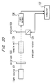
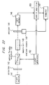
- FIG. 20 An example of the conventional polarimeter is shown in Fig. 20.
- a light source 121 is configured of a sodium lamp, a band-pass filter, a lens, a slit, etc. for projecting a substantially parallel light composed of a sodium D ray having a wavelength of 589 nm.
- a polarizer 122 is arranged in the direction of advance of the light projected from the light source 121 in such a position as to transmit only a component in a specific direction, which has a plane of vibration coincident with a transmission axis thereof, of the light projected from the light source 121.
- a sample cell 123 for holding a specimen is arranged in the direction of advance of the light transmitted through the polarizer 122.
- an analyzer 124 is arranged, like the polarizer 122, in such a position as to transmit only the component of the light in a specific direction.
- An analyzer rotator 125 is for rotating the analyzer 124 on an axis parallel with the direction of advance of the light projected from the light source 121 under the control of a computer 127.
- a light sensor 126 is for detecting the light projected from the light source 121 and transmitted through the polarizer 122, the sample cell 123 and the analyzer 124.
- the computer 127 controls the analyzer rotator 125 while recording and analyzing a signal from the light sensor 126.
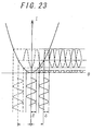
- the abscissa represents the relative angle ⁇ formed between the plane of vibration of the light transmitted through the polarizer 122 and the plane of vibration of the light transmitted through the analyzer 126.
- ⁇ is assumed to take zero when the angle between these two planes of vibration reaches ⁇ /2, i.e., in the orthogonal nicol state.
- the ordinate represents an intensity I of the light that has reached the light sensor 126 based on an output signal of the light sensor 126.
- the solid line indicates the output signal in the case where the specimen exhibits no optical rotatory power.
- equation (1) the relation between ⁇ and I is shown by equation (1) mentioned below.
- I T ⁇ I o ⁇ (cos ⁇ ) 2
- I changes with a change of ⁇ , i.e., with the rotation of the analyzer 126, so that an extinction point with a minimum I appears for each ⁇ .
- a specimen having an optical rotatory power as compared with a specimen having no optical rotatory power, has the angle associated with the extinction point displaced by ⁇ .
- the angle of rotation can be measured by finding the displacement ⁇ of the angle associated with the extinction point by the computer 127.
- a polarimeter shown in Fig. 22 is also used in order to improve an accuracy of determining the extinction point.
- a light source 141 is configured of a sodium lamp, a band-pass filter, a lens, a slit, etc. for projecting a substantially parallel light of sodium D ray having a wavelength of 589 nm.
- a polarizer 142 and an analyzer 144 are arranged in the direction of advance of the light projected from the light source 141 aligning their transmission axes with the direction of advance of the light projected from the light source 141, with a sample cell holding a specimen interposed therebetween.
- An analyzer rotator 145 is for rotating the analyzer 144 on the transmission axis thereof as a rotation shaft under the control of a computer 147.
- a light sensor 146 detects the light projected from the light source 141 and transmitted through the polarizer 142, the sample cell 143 and the analyzer 144.
- the computer 147 controls the analyzer rotator 145, and records and analyzes the signal of the light sensor 146.
- An optical Faraday modulator 151 vibrates the direction of polarization.
- a signal generator 152 drives the optical Faraday modulator 151.
- a lock-in amplifier 143 is for phase sensitive detection of an output signal of the light sensor 146 with reference to the vibration-modulated signal from the optical Faraday modulator 151.
- the abscissa and the ordinate represent, as same in Fig. 21, ⁇ and I, respectively, with the extinction point and the neighborhood thereof shown in an enlarged view.
- the optical Faraday modulator 151 vibration-modulates the direction of polarization with an amplitude of ⁇ and an angular frequency of ⁇ .
- I is given as shown in equation (3) below from equation (2).
- I T ⁇ I o ⁇ ⁇ cos( ⁇ - ⁇ + ⁇ ⁇ sin( ⁇ ⁇ t)) ⁇ 2
- equation (5) is approximated as shown in equation (6) below.
- the phase sensitive detection of the value I with the vibration-modulated signal as a reference signal in the lock-in amplifier it is possible to pick up the component of the angular frequency ⁇ , i.e., the value S shown in equation (7) below.
- S T ⁇ I o ⁇ 2 ⁇ ( ⁇ - ⁇ ) ⁇ ⁇
- modulation of the direction of polarization makes it possible to pick up the signal of the modulated frequency component selectively by separating it from noises such as a source light intensity, power fluctuations and radiation, thereby making it possible to obtain the signal S with high S/N.
- This value S can be used to determine the extinction point accurately and permits a highly accurate measurement of the angle ⁇ of rotation.
- the above-mentioned polarimeter is complicated in structure due to the need of a means for rotating the analyzer and a modulator, and therefore has its own limit of cost reduction and reliability.
- the object of the present invention is to provide a method of urinalysis easy to maintain and manage without using supplies such as a test paper. Further, the object of the present invention is to provide a reliable, compact and inexpensive polarimeter and a urinalysis apparatus using this one.
- a concentration of an optically active substance contained in urine is determined by measuring an angle of rotation of the urine.
- Glucose and protein existing in the urine exhibit an optical rotatory power whereas urea and uric acid constituting the main components of the organic substances in the urine have no optical rotatory power.
- none of the inorganic substances in the urine exhibits the optically rotatory power.
- the concentration of glucose or protein in the urine can be accurately determined by measuring the angle of rotation of the urine.
- the concentration of L-ascorbic acid which may be contained in the urine can also be determined by measuring the angle of rotation.
- the angle of rotation of the urine is measured by using a high-precision polarimeter, therefore, the angle of rotation due to the optically active substances like glucose and protein existing in low concentration can be detected thereby making it possible to calculate the concentration of these substances. As a result, the concentration of the glucose and protein in the urine can be examined without using any supplies.
- the present invention provides a highly accurate, reliable, compact and inexpensive polarimeter which solves the above-mentioned problems of the conventional polarimeter.
- the angle A of rotation is proportional to the product of a specific angle ⁇ of rotation and the concentration C of an optically active substance. This relation is shown by equations (8) and (9).
- the specific angles of rotation shown above are values for a glucose aqueous solution and an albumin aqueous solution at 20 ° C.
- a urine glucose level can be calculated from the specific angle of rotation of glucose by measuring the angle of rotation of the urine.
- a similar calculation is possible also for albumin and L-ascorbic acid.
- an angle of rotation of urine having a known range of angle of rotation presented by an interfering optically active substance other than optically active substance of unknown concentration is measured, and the concentration C of the optically active substance is determined to be within the range of (A - A h )/( ⁇ ⁇ L) ⁇ C ⁇ (A - A l )/( ⁇ ⁇ L) where
- equation (9) is modified to obtain equation (11) below.
- equation (2) assume that substance 1 is an optically active substance X to be detected, and substances 2 --- N are other optically active substances, i.e., interfering optically active substances, A d corresponds to the angle of rotation presented by the interfering optically active substances. If the concentration range of the substances 2 to N is known, the maximum value A h and the minimum value A l that A d can assume are known. This leads to equation (12) below.
- a - A h ⁇ A x A - A d ⁇ A - A l
- Equation (12) determines the range of the angle A x of rotation, and the concentration C x is also determined from the specific angle ⁇ x of rotation and the length L of the measurement optical path. Equation (12) is expressed as equation (10) in terms of the concentration C of the optically active substance X.
- the examination with the above-described accuracy often suffices.
- the abnormality of the sugar in the urine can be determined by measuring the angle of rotation with a single wavelength.
- angles of rotation of the urine including N types of optically active substances is measured using the light having N different types of wavelength thereby to determine the concentrations of the optically active substances in the urine.
- the specific angle of rotation varies with wavelength due to optically rotatory dispersion. Consequently, in the case where N types of optically active substances coexist, N independent simultaneous equations can be obtained using equation (9) by measuring the angle of rotation by each of the N wavelengths. This makes it possible to calculate the concentration for N types of optically active substances.
- the abnormality of the sugar or the albumin concentration in the urine can be determined by measuring the angle of rotation of the urine.
- the angle of rotation of the urine for the light having a wavelength of not less than 500 nm is measured.
- the absorption due to urochrome a yellow component of urine
- the concentration of a light-scattering substance contained in the urine is determined by measuring an amount of a light scattered in the urine.
- the light scattering substance is at least one of protein and blood.
- the molecular weight of the albumin constituting protein in the urine is about 70 thousands, which causes light scattering sufficiently large as compared with the light scattering due to the molecular weight of other organic substances including glucose (having a molecular weight of about 180) or the like and inorganic substances contained in the urine.
- the scattering of the light propagating in the urine is dominated by albumin.
- the albumin concentration can be determined by irradiating light to the urine and observing the scattered light directly or in the form of the decreasing amount of the transmitted light. It is also possible to examine the presence or absence of the blood which have comparatively large particles.
- the amount of the scattered light in the urine is measured for the light having a wavelength of not less than 500 nm.
- the light having a wavelength of shorter than 500 nm involves an increased absorption mainly due to urochrome, often adversely affecting the measurement accuracy.
- the amount of the scattered light is measured together with the angle of rotation of the urine thereby to determine the concentration of the light scattering substances as well as the optically active substances contained in the urine. This is effective especially in the case where both glucose and albumin exist in an amount not negligible in the urine.
- the concentration of sugar and protein in the urine can be easily and accurately determined by measuring the angle of rotation of the urine.
- This method also eliminates the need of supplies such as the test paper unlike in the prior method.
- an angle of rotation of a specimen is measured by applying a magnetic field to the specimen and detecting the change in the direction of polarization of the light due to the magnetic field.
- the present invention provides a polarimeter comprising a monochromatic light source for projecting the light, a polarizer for transmitting only the polarized component in a specific direction of the projected light, a sample cell for holding the specimen and arranged in such a manner that the light passed through the polarizer is transmitted through the specimen, means for applying a magnetic field to the specimen, means for sweeping the magnetic field, an analyzer for transmitting only the polarized component in a specific direction of the light transmitted through the specimen, a light sensor for detecting the light transmitted through the analyzer, and calculation means for calculating an angle of rotation of the specimen on the basis of a magnetic field sweep signal of the magnetic field sweeping means and an output signal of the light sensor.
- V in equation (13) is varied with the medium, light wavelength and temperature.
- An example of V for various media is shown in Table 2.
- This optical Faraday effect is utilized by the optical Faraday modulator used in the prior art. This is such that a solenoid coil is wound on a rod of flint glass and is supplied with a current to apply a magnetic field thereto, thereby modulating the direction of polarization of the light propagated in the direction of the magnetic field. Free modulation can be conducted by controlling the current flowing in the solenoid coil.
- the optical Faraday effect permits the modulation of the polarization direction upon application of a magnetic field to a medium.
- Table 2 this is also the case with water, chloroform, acetone or the like widely used as a solvent. Therefore, upon application of a magnetic field to a solution with a specimen dissolved therein, the very solution rotates the direction of polarization of the light propagating through the solution by the optical Faraday effect.
- the particular sample cell and the magnetic field application means function as an optical Faraday modulator.
- a solenoid coil, a magnet etc. which apply the magnetic field in the direction of light propagation can be used as a magnetic field application means.
- the magnetic field can be modulated by modulating the current flowing in the solenoid coil or by modulating the distance between the magnet and the specimen.
- the direction of polarization can be vibration-modulated by vibration-modulating the magnetic field, thereby making it possible to measure the angle of rotation in the same manner as in the prior art.
- the direction of polarization of the magnetic field can be rotated.
- the method of measuring the angle of rotation according to the present invention is such that the displacement of the extinction point with the magnetic field swept is read by a current value, for example, which is converted into a magnetic field and further into an angle, thereby measuring the angle of rotation of the specimen. This is substantially the same as if a magnetic field is detected in which the angle of rotation generated by an optically active substance of a specimen coincides with the rotational angle of the direction of polarization due to the optical Faraday effect caused by an application of the magnetic field.
- Sweeping of the magnetic field is not necessarily limited to a continuous change of strength but includes a discrete change thereof.
- the angle of rotation can be calculated by measurements taken at two or more points and interpolation or extrapolation from the measurements. Specifically, the angle of rotation of a specimen can be calculated from the output signals of the light sensor for at least two different magnetic fields. In such a case, the measurement time can be shortened.
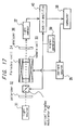
- Fig. 1 is a schematic diagram showing a configuration of a polarimeter used in an embodiment of the present invention.
- Fig. 2 is a characteristic diagram showing the relation between a glucose concentration of an aqueous solution of glucose or urine with glucose dissolved therein and an angle of rotation obtained by a measurement using the same polarimeter.
- Fig. 3 is a schematic diagram showing a configuration of a polarimeter used in another embodiment of the present invention.
- Fig. 4 is a characteristic diagram showing the relation between a glucose concentration of glucose aqueous solution or an albumin concentration of an albumin aqueous solution and the angle of rotation for the light having a wavelength of 830 nm obtained by a measurement using the same polarimeter.
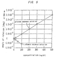
- Fig. 5 is a characteristic diagram showing a relation between concentrations of the same aqueous solutions and angles of rotation for a light having a wavelength of 589 nm.
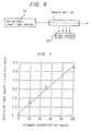
- Fig. 6 is a schematic diagram showing a configuration of a scattered light amount measuring instrument used in another embodiment of the present invention.
- Fig. 7 is a characteristic diagram showing a relation between a concentration of an albumin aqueous solution and a scattered light amount obtained by using the same measuring instrument.
- Fig. 8 is a characteristic diagram showing a relation between a wavelength of the incident light and an intensity of a light transmitted through the urine.
- Fig. 9 is a schematic diagram showing a configuration of a polarimeter used in another embodiment of the invention.
- Fig. 10 is a characteristic diagram showing a relation between the amount of the current flowing in a solenoid coil and an output signal of the light sensor obtained by using the same polarimeter.
- Fig. 11 is a characteristic diagram showing a relation between a concentration of an aqueous solution of cane sugar and the output signal of the light sensor obtained by using the same polarimeter.
- Fig. 12 is a schematic diagram showing a configuration of a polarimeter according to still another embodiment of the present invention.
- Fig. 13 is a characteristic diagram showing a relation between a current amount J supplied to the solenoid coil and an output signal of a lock-in amplifier obtained by using the same polarimeter.
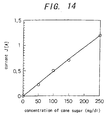
- Fig. 14 is a characteristic diagram showing a relation between a concentration of an aqueous solution of cane sugar and an output signal of the light sensor obtained by using the polarimeter.
- Fig. 15 is a characteristic diagram showing a relation between a glucose concentration of a glucose aqueous solution or a urine with glucose dissolved therein and an angle of rotation obtained by a measurement using the polarimeter.
- Fig. 16 is a schematic diagram showing a configuration of a polarimeter according to still further embodiment of the present invention.
- Fig. 17 is a schematic diagram showing a configuration of a polarimeter according to yet still further embodiment of the present invention.
- Fig. 18 is a schematic diagram showing a configuration of a polarimeter according to a further embodiment of the present invention.
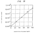
- Fig. 19 is a characteristic diagram showing the relation between a standardized variable X and a concentration of an aqueous solution of glucose obtained by using the polarimeter.
- Fig. 20 is a schematic diagram showing a conventional polarimeter.
- Fig. 21 is a characteristic diagram showing a relation between a rotational angle ⁇ and a detected light intensity based on the principle of measurement of the polarimeter.
- Fig. 22 is a schematic diagram showing another polarimeter.
- Fig. 23 is a characteristic diagram showing the relation between the rotational angle ⁇ and the detected light intensity based on the principle of measurement of the polarimeter.
- Fig. 1 is a diagram showing a configuration of a polarimeter used in the present embodiment.
- the basic principle of this polarimeter is the optical zero-order method based on the vibration of the plane of polarization using the Faraday effect.
- a low-pressure 180 W sodium lamp 1 emits a parallel light.
- a band-pass filter 2 transmits only the components having a wavelength of 589.0 nm of the light emitted from the sodium lamp 1.
- a polarizer 3 passes specific component of the polarized light from the bandpass filter 2 which have a plane of vibration parallel to the page, for example.
- a modulated signal current input from a Faraday cell driver 5 causes the Faraday cell 4 to modulate the direction of polarization of the transmitted light by a very small width due to the optical Faraday effect.
- the substantial length of the light path of a sample cell 6 for containing the urine is 10 cm.
- a light sensor 9 detects the light transmitted through the rotary analyzer 7 and outputs a signal based on the intensity of the light thus detected.
- a lock-in amplifier 10 subjects the output of the light sensor 9 to phase sensitive detection with the modulated signal applied to the Faraday cell 4 as a reference signal.
- a computer 11 applies to the analyzer driver 8 an instruction for continuously rotating the rotary analyzer 7 while recording the output of the lock-in amplifier 10. As a result, the angle of the rotary analyzer 7 at which the output of the lock-in amplifier 10 becomes zero is found to calculate the angle of rotation. With the above-mentioned configuration, the accuracy of about 10 -3 is achieved.
- the urine was analyzed as described below using this polarimeter.
- the angle of rotation was measured of the urine determined to have a glucose concentration of 50 mg/dl or less and an albumin concentration of 10 mg/dl or less by the urinalysis made in advance using the test paper. Further, with this urine as a solvent, glucose solutions having concentrations of 20, 100, 200, 300 and 500 mg/dl, respectively, in other words, artificial glycosuria were prepared, and the angle of rotation of these were measured. The result is shown by black circles in Fig. 2. The angle of rotation of these artificially-prepared glycosuria is represented by a straight line translated in parallel from the analytical curve by 1.5 ⁇ 10 -2 degrees and accurately reflects the glucose concentrations.
- the angle of rotation of the urine itself was 1.5 ⁇ 10 -2 degrees. This, combined with the range of albumin concentration obtained in advance by urinalysis, can decide from equation (10) the glucose concentration C as 30 mg/dl ⁇ C ⁇ 42 mg/dl This coincides with the result of analysis obtained beforehand.
- the angle of rotation was measured similarly of the urine determined by an urinalysis apparatus to have a glucose concentration of 30 mg/dl or more and a normal albumin concentration, i.e., 10 mg/dl or less. As a result, this urine exhibited the angle of rotation of 2.2 ⁇ 10 -1 degrees.
- This combined with the range of albumin concentration obtained in advance by the urinalysis apparatus, shows that the glucose concentration C is 440 mg/dl ⁇ C ⁇ 452 mg/dl This also coincides with the result of analysis obtained in advance.
- an abnormal glucose concentration of the urine (urine glucose level) can be accurately detected by measuring the angle of rotation.
- the glucose concentration of 300 mg/dl or more can be determined with an error of about 12 mg/dl.
- the urine glucose level can be examined without using any supplies such as test paper, thereby greatly contributing to practical effects.
- a polarimeter shown in Fig. 3 was used together with the polarimeter shown in the first embodiment.
- This polarimeter like the polarimeter of the first embodiment, operates on the basic principle of the optical zero-order method based on the vibration of the plane of polarization using the Faraday effect.
- Numerals 3 to 11 designate the same components as the corresponding ones used in the first embodiment.
- a semiconductor laser light source 12 was used in place of the sodium lamp.
- the semiconductor laser light source 12 projects a parallel light of 5 mW having an emission wavelength of 830 nm.
- This polarimeter operates in the same manner as the corresponding one of the first embodiment and achieved the accuracy of about 10 -3 degrees.
- Equation (9) and the specific angles of rotation in Table 1 give simultaneous equations shown in equations (14) and (15).
- a 589 0.1 ⁇ (50C 1 - 60C 2 )
- a 830 0.1 ⁇ (25C 1 - 10C 2 )
- the angle of rotation was measured of the urine which had been decided to have a glucose concentration of 50 mg/dl or less and an albumin concentration of 100 mg/dl or more as a result of the conventional urinalysis using the test paper.
- the angle of rotation was measured of the urine which had been decided to have a glucose concentration of 300 mg/dl or more and an albumin concentration of 100 mg/dl or more.
- a 830 8 ⁇ 10 -2 [degrees] Equations (14) and (15) were solved using this result thereby to obtain a glucose concentration of 380 mg/dl and an albumin concentration of 150 mg/dl. This coincides with the result of the conventional urinalysis.
- the urine glucose level and the albumin concentration thereof can be examined without using any supplies such as the test paper by determining the angles of rotation using a plurality of light having different wavelengths.
- a urinalysis apparatus will be explained below with reference to Fig. 6.
- a helium neon laser 13 is adapted to project parallel light 5 mW in output having a wavelength of 633 nm onto a sample cell 14 containing the urine.
- the sample cell 14 has a substantial light path length of 10 cm and a width of 1 cm. Since the sample cell 14 has the two transparent sides, a scattered light in direction perpendicular to the light path can pass outward of the sample cell 14.
- a light sensor 15 is arranged with the angle of visibility thereof coinciding with the sample cell 14 and capable of detecting the scattered components of the laser light propagating in the urine.
- the scattered light amount was measured of the urine that had been decided to have a glucose concentration of 50 mg/dl or less and an albumin concentration of 10 mg/dl or less by the analysis using the test paper, but the scattered light could not be detected.
- a measurement of the urine that had been decided to have a glucose concentration of 300 mg/dl or more and an albumin concentration of 10 mg/dl or more by the conventional urinalysis method confirmed the presence of a signal of about 6 on the scale in Fig. 7. Further, a signal of about 6 could also be confirmed by another measurement of an urine that had been decided to have a glucose concentration of 50 mg/dl or less and an albumin concentration of 100 mg/dl or more by the conventional urinalysis method. In the process, the scattered light amount was measured on an arbitrary scale.
- the albumin concentration can be determined by measuring the amount of the scattered components of the light propagating in the urine.
- scattering of the light due to comparatively large particles such as albumin or blood is sufficiently large as compared with the scattering of the light due to glucose or other organic or inorganic substances in the urine.
- scattering of the light propagating in the urine due to albumin and blood is controlling. Consequently, it is possible to determine the albumin concentration or the blood concentration in the urine by irradiating light into the urine and observing the amount of scattered light.
- the presence of large particles such as albumin and blood can be examined without using any supplies like the test paper, thereby greatly contributing to practical effects.
- the polarimeter shown in Fig. 3 and explained in the second embodiment is used as it is.
- the principle of measuring the angle of rotation is similar to that for the second embodiment.
- This method can determine the angle of rotation and the scattered light amount at the same time in a single measurement process, and it is thus possible to determine the concentration of a light-scattering substance such as albumin.
- a light-scattering substance such as albumin.
- the range of concentration of albumin and the like required in advance in the first embodiment can be grasped, and therefore the glucose concentration can also be determined.
- the glucose concentration and the albumin concentration in the urine can be examined at the same time with a simple configuration and a single measurement, thereby greatly contributing to practical effects.
- Another method available for measuring the amount of the scattered light is to temporarily fix the rotary analyzer 7 at a predetermined angle and to determine the amount from an associated output value of the lock-in amplifier 10.
- a similar effect can of course be obtained by directly detecting the scattered light from the side of the sample cell 6 as in the third embodiment.
- the angle of rotation increases, however, with the decrease in the wavelength of the measured light due to the optically rotatory dispersion until the appearance of an abnormal dispersion. Consequently, although the light of a shorter wavelength can be used more advantageously for high accuracy measurement, the light having a wavelength of about 500 nm or more is more desirable for urinalysis. This is by reason of the fact that as obvious from Fig. 8 showing the spectral characteristic of normal urine, the light having a wavelength shorter than 500 nm is absorbed increasingly by urochrome (a yellow component contained in the urine), sometimes deteriorating the measurement accuracy. For similar reason, the desirable wavelength of the light used for measuring the scattered light amount is 500 nm or more due to the absorption of urochrome.
- the embodiments described above concern a method of determining the glucose concentration and the albumin concentration in urine by projecting monochromatic light on the urine and determining the angle of rotation of the urine or the amount of the light scattered in the urine.
- the polarimeters used for the urinalysis have the problem of a low reliability and a high cost as described above. In view of this, detailed description will be made below about a polarimeter higher in reliability and lower in cost than the conventional polarimeters and the urinalysis apparatus using such a polarimeter.
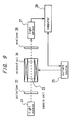
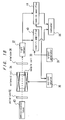
- a configuration of a polarimeter according to this embodiment is shown in Fig. 9.
- a light source 21 configured of a 180 W low-pressure sodium lamp, a bandpass filter, a lens, a slit, etc. for projecting substantially parallel light is adapted to project a sodium D ray having a wavelength of 589.0 nm.
- a polarizer 22 allows only the component in a specific direction having a plane of vibration parallel to the transmission axis to pass therethrough.
- a specimen is held in a cylindrical sample cell 23 of glass.
- the sample cell 23 is arranged in such a position that the substantially parallel light projected from the light source 21 and polarized by being passed through the polarizer 22 enters and passes along the direction of the central axis thereof.
- the substantial light path length of this sample cell 23 is 300 mm.
- a solenoid coil 24 wound around the sample cell 23 applies a magnetic field substantially uniformly to the sample cell 23 and the specimen held therein in the direction of propagation of the light by the current from the current source 25.
- a current of 1 A applied to the solenoid coil 24 causes a magnetic field H of 5 ⁇ 10 3 A/m.
- the current source 25 can supply a current of -5 A to 5 A to the solenoid coil 24.
- the analyzer 26 is arranged in such a position as to transmit only those components of the light transmitted through the sample cell 23 which are polarized in the direction perpendicular to the page, in other words in orthogonal nicol state with the polarizer 22.
- a light sensor 27 detects the light transmitted through the analyzer 26.
- a computer 28 issues a command signal to the current source 25 to record and analyze on output signal of the light sensor 27.
- the computer 28 issues a command signal to the current source 25 so that the current flowing in the solenoid coil 24 is swept from -5 A to 5 A.
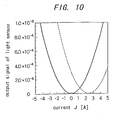
- the output signal of the light sensor 27 produced in the process is shown in Fig. 10.
- the abscissa represents a current J flowing in the solenoid coil 24, and the ordinate represents an output signal (arbitrary value) of the light sensor 27.
- the solid line is associated with the case in which the pure water exhibiting no optical rotatory power is measured as a specimen.
- J When J is changed, the output signal of the light sensor 27 changes according to equation (13) in a manner similar to the case where the analyzer is rotated in the conventional polarimeter. In the polarimeter in this embodiment, however, J corresponds to ⁇ in equation (4).
- the dotted line in the drawing shows a cane sugar aqueous solution of 20°C in temperature and 500 mg/dl in concentration as a specimen.
- the curve is obtained by translating the curve indicated by the solid line in the drawing horizontally along the abscissa by +2.4 A.
- This 2.4 A displacement of the extinction point is caused by the angle of rotation of the specimen.
- This polarimeter determines the angle of rotation of the specimen from the magnitude of this displacement.
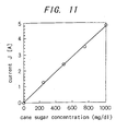
- the angle of rotation was measured of the cane sugar aqueous solution having the concentrations of 250, 750 and 1000 mg/dl, respectively, at the temperature of 20°C.
- the result is shown in Fig. 11.
- the abscissa represents the cane sugar concentration
- the ordinate represents the current J when an extinction point appears. This is indicative of the fact that the output signal of the light sensor can be approximated linearly with respect to the cane sugar concentration.
- the conventional polarimeter measures the displacement of an extinction point, i.e., the angle of rotation of a specimen by rotating an analyzer and reading the angle of the analyzer directly.
- a magnetic field is applied to the specimen with being swept and the displacement of the extinction point is read in terms of current. This current value is converted into a magnetic field intensity and further into an angle thereby to calculate the angle of rotation of the specimen.
- a magnetic field is applied to the specimen and swept, thereby eliminating the need of means for rotating the analyzer. Consequently, it is possible to realize a reliable, compact and inexpensive polarimeter of a very high practical value.
- the intensity is not necessarily changed continuously but can be changed discretely. Since the characteristic of the output signal of the light sensor changing with the rotation of the direction of polarization is known as shown in equation (2), the angle of rotation can be calculated by measuring the magnetic field intensity at least two points and by interpolation or extrapolation of the measurements. This process is especially effective for shortening the measurement time.
- a light source 31 similar to the one used in the fifth embodiment projects the sodium D ray having a wavelength in 589.0 mm.
- a polarizer 32 allows only the polarized light component in a specified direction, for example, only those polarized light components that are parallel to the page to transmit.
- a cylindrical sample cell 33 for holding the specimen is made of glass and has a substantial light path length of 50 mm.
- the analyzer 36 is arranged in such an orthogonal nicol state with the polarizer 32 that only the polarized light components perpendicular to the page are transmitted.
- a light sensor 37 detects the light transmitted through the analyzer 36.
- a computer 38 issues a command signal to a current source 35, while recording and analyzing the output signal of the light sensor 37. Also, the computer 38 issues a command signal to the current source 35 and causes the current flowing in the solenoid coil 34 to be swept up from -5 A to 5 A.
- the solenoid coil 34 has a structure substantially similar to the one used in the fifth embodiment, and applies a magnetic field H of 5 ⁇ 10 3 A/m to the sample cell 33 with a current of 1 A.
- a signal generator 39 supplies a vibration-modulated signal to the current source 35.
- the current source 35 converts the vibration-modulated signal into a vibration-modulated current signal, and superimposes it on the sweeping current commanded by the computer 38, then the resulting current obtained is applied to the solenoid coil 34.
- the 1.3 kHz modulated signal is converted into a vibration-modulated current signal having an amplitude of 0.02 A, which is supplied to the solenoid coil 34.
- the lock-in amplifier 40 phase-sensitively detects the output signal of the light sensor 37 with reference to the vibration- modulated signal of the signal generator 39.
- the output signal of the lock-in amplifier 40 corresponds to the angular frequency component ⁇ of the output signal of the light sensor 37 in equation (6), i.e., S shown in equation (7).
- the extinction point therefore, corresponds to the time when the value S becomes zero.
- the operation of the polarimeter will be explained with reference to Fig. 13.
- the computer 38 issues a command signal to the current source 35, and the current flowing in the solenoid coil 34 is swept from -1.5 to 1.5 A.
- the resulting output signal of the lock-in amplifier 40 is shown.
- the abscissa represents the current J flowing in the solenoid coil 34, and the ordinate the output signal (arbitrary value) of the lock-in amplifier 40.
- the solid line represents the measurement of pure water having no optically rotatory power.
- the dotted line indicates the measurement of the cane sugar aqueous solution having a concentration of 250 mg/dl at 20°C in temperature as a specimen.
- a new straight line is obtained by translating the solid line by the length of + 1.21 A in parallel. This is quantitatively confirmed in a similar manner to the fifth embodiment.
- the rotational angle a of the direction of polarization due to the optical Faraday effect can be calculated from equation (13) as follows.
- the analyzer is rotated, and the angle of the analyzer is directly read when the output signal of the lock-in amplifier, i.e., the value S assumes zero.
- the magnetic field is swept, i.e., the current is swept, and the current value is read when the output signal S of the lock-in amplifier 40 becomes zero, and is further converted into the angle thereby to measure the angle of rotation of the specimen.
- an extinction point exists in the sweeping range of the magnetic field.
- the output signal S of the lock-in amplifier 40 changes linearly with respect to the magnetic field, i.e., the current J as shown in Fig. 13 and equation (7), even in the absence of an extinction point within the sweeping range, the angle of rotation can be calculated by extrapolation.
- the relation between J and S is linear, continuous sweeping is not necessarily required, and the angle of rotation can be calculated by interpolation or extrapolation from measurements at two or more points in the magnetic field. This enables to shorten a measurement time.
- the error due to the contamination of the sample cell can be compensated.
- the time length before cleaning or replacing the sample cell after a long time of repetitive uses can be lengthened considerably until the transmittance of the plane of transmission is reduced to a specified value, thus facilitating maintenance and management.
- the apparatus is used as a home urine analyzer, the maintenance and management ease greatly contributes to the extension of its application.
- the polarimeter according to this embodiment permits measurement with a higher accuracy than that of the fifth embodiment, and therefore measurement of the angle of rotation of a solution with a low concentration is also possible. Further, the fact that the light path length can be shortened contributes to a smaller size of the apparatus.
- the angle of rotation was measured of the urine which had been determined to have a glucose concentration of not more than 50 mg/dl and a concentration of albumin which is urine protein of not more than 10 mg/dl. Further, with this urine as a solvent, glucose solutions, i.e., artificial glycosuria 20, 100, 200, 300 and 500 mg/dl in concentration were prepared. Then, the angle of rotation of these artificial glycosuria was measured. The result is shown by black circles in Fig. 19. The angle of rotation of these artificial glycosuria (black circles) is represented by a straight line translated by 1.5 ⁇ 10 -2 degrees from the analytical line and accurately reflects the glucose concentrations.
- the angle of rotation of this urine was 1.5 ⁇ 10 -2 degrees. This is the result of simple addition of the angles of rotation due to the glucose and albumin existing in the urine.
- the range of the glucose concentration Cg can be calculated from equation (9) in the manner shown below. 30 mg/dl ⁇ Cg ⁇ 42 mg/dl This coincides with the result of the analysis made beforehand.
- the angle of rotation was measured of the urine which had been decided to have a glucose concentration of 300 mg/dl or more and an albumin concentration of 10 mg/dl or less by the urinalysis using the test paper.
- the result was that the angle of rotation of this urine was 2.2 ⁇ 10 -2 degrees with the glucose concentration Cg determined to be in the range described below.
- 440 mg/dl ⁇ Cg ⁇ 452 mg/dl This also coincides with the analysis made in advance.
- the angle of rotation of urine can be measured to determine the concentration of glucose, protein, etc. in the urine simply by placing the urine in the sample cell of the polarimeter and applying a magnetic field to it.
- the polarimeter requires no supplies and is easy to maintain and manage and high in reliability, thus realizing a compact and inexpensive urinalysis apparatus.
- this polarimeter When this polarimeter is used as a urinalysis apparatus, even in the case where the sample cell is contaminated by the routine urinalysis, the use of the polarimeter under consideration with the urinalysis apparatus makes it is possible to maintain a high measurement accuracy by measuring a reference specimen with a known angle of rotation and correcting the measurement of the specimen involved. As a result of this operation, the time length before cleaning or replacing the sample cell can be extended until the transmittance of the plane of transmission is reduced to a specified value. Especially when it is used as a home urinalysis apparatus, the maintenance and management ease is a great factor for promoting the extension of the use thereof the apparatus.
- the embodiment described above concerns the examination in which the albumin concentration of the urine examined is low as compared with the glucose concentration thereof, the method mentioned above can also apply with the same effect to analyzing the albumin concentration of the urine low in which the glucose concentration is low as compared with the albumin concentration.
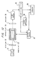
- FIG. 16 A polarimeter according to this embodiment will be explained with reference to Fig. 16.
- numerals 31 to 40 designate components similar to the corresponding ones in the sixth embodiment.
- the current source 35 converts a modulated signal of 1.3 kHz into a vibration-modulated current signal having an amplitude of 0.02 A, and supplies it to the solenoid coil 33, although the current is not swept.
- the analyzer rotator 41 rotates the analyzer 36 in response to a command from the computer 38.
- the output signal of the lock-in amplifier 40 similarly corresponds to the angular frequency component ⁇ of the output signal of the light sensor 37 in equation (6), i.e., S in equation (7).
- the computer 38 issues a command signal to the analyzer rotator 41 thereby to rotate the analyzer 36.
- the angle of the analyzer 46 is plotted along the abscissa, and the output signal S of the lock-in amplifier 40 is plotted along the ordinate, a straight line similar to that in Fig. 13 is obtained.
- the angle of the analyzer 36 when the output signal S of the lock-in amplifier 40 becomes zero corresponds to the angle of rotation of the specimen.
- the analyzer is rotated while vibration-modulating the direction of polarization by the optical Faraday modulator, and the angle of the analyzer associated with the time when the output signal of the lock-in amplifier, i.e., S is zero is read directly to measure the angle of rotation of the specimen.
- a magnetic field is applied to the specimen and vibration-modulated, then, the angle of the analyzer associated with a zero output signal S of the lock-in amplifier is read directly to measure the angle of rotation of the specimen.
- the relation between the angle of the analyzer and S can be approximated by a linear expression. Therefore, continuous sweep is not necessarily required, but the angle of rotation can be calculated by interpolation or extrapolation based on the measurements at two or more points.
- polarimeter according to this embodiment can make measurement with a higher accuracy than the polarimeter of the fifth embodiment, the angle of rotation of a solution lower in concentration can also be measured. Further, the fact that a sample cell shorter in light path length can be used contributes to a reduced size of the apparatus.
- FIG. 17 A polarimeter according to this embodiment will be explained with reference to Fig. 17.
- numerals 31 to 40 designate the same component parts which have the same functions as the corresponding ones in the sixth embodiment.
- the current source 35 sweeps the current supplied to the solenoid coil 33 in response to a command from the computer 38.
- the optical Faraday modulator 42 vibration-modulates the direction of polarization of the light with an amplitude of 1.4 ⁇ 10 -3 degrees by a vibration-modulated signal of 1.3 kHz generated by a signal generator 39.
- the lock-in amplifier 40 phase-sensitively detects the output signal of the light sensor 37 with reference to the vibration-modulated signal of the signal generator 39.
- the output signal of the lock-in amplifier 40 corresponds to the angular frequency component ⁇ of the output signal of the light sensor 37 in equation (6), i.e., S shown in equation (7). Therefore, an extinction point develops when the value S becomes zero.
- the output signal S of the lock-in amplifier is linearly approximated by the magnetic field, i.e, the current J, therefore continuous sweep is not necessarily required, but the angle of rotation can be calculated by interpolation or extrapolation from the measurements at two or more points in the magnetic field. This also shortens the measurement time.
- the direction of polarization is vibration-modulated with a minute amplitude by the optical Faraday modulator, a magnetic field is applied to the specimen, and the magnetic field is swept, thereby eliminating the means of rotating the analyzer, and realizing a compact, inexpensive polarimeter of a great practical value high in accuracy and reliability easy to maintain and manage.
- the polarimeter according to this embodiment can measure with a higher accuracy than that of the fifth embodiment, and therefore can measure the angle of rotation of a solution low in concentration. Also, measurement of a specimen with a small light path length thus is possible, which is another factor contributing to a compact apparatus.
- the optical Faraday modulator is used for modulating the direction of polarization in this embodiment, a piezoelectric device can be used in place of the optical Faraday modulator for minute vibratory rotation with a similar effect.
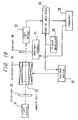
- a polarimeter according to this embodiment will be explained with reference to Fig. 18.
- numerals 32 to 40 designate component parts which are similar and function similarly to the corresponding parts in the sixth embodiment.
- a semiconductor laser light source 43 is used instead of the sodium light source.
- the semiconductor laser light source 43 projects substantially parallel light having a wavelength of 830 nm and an intensity of 10 mW.
- the current source 35 converts a modulated signal at 1.3 kHz generated by a signal generator 39 into a vibration-modulated signal having an amplitude of 0.02 A, and supplies it to the solenoid coil 44. But the current is not swept unlike in the foregoing embodiment.
- the lock-in amplifier 34 operates in what is called 2F-mode, and phase-sensitively detects the output signal of the light sensor 37 with reference to a signal having a frequency twice that of the modulated signal of the signal generator 39. Specifically, the lock-in amplifier 34 retrieves the 2 ⁇ ⁇ component of equation (6).
- the computer 38 standardizes the output signal of the lock-in amplifier 40 by the output signal of the lock-in amplifier 44 and thus calculates the angle of rotation of the specimen. The principle of this operation is described below.
- the output signal of the lock-in amplifier 44 corresponds to S shown in equation (7). Since this value S has a sole function in the case where ⁇ is fixed and the values T, I o and ⁇ are constant as in the present embodiment, therefore, the angle of rotation ⁇ can be uniquely calculated from S. Actually, however, T is varied due to the difference in transmittance between specimens, the contamination of the transmission window of the specimen, etc. Also, I o changes with fluctuations of the source light intensity, and therefore, it is impossible to measure the angle of rotation with high accuracy solely from the value S.
- the output signal of the lock-in amplifier 44 is utilized.
- X 4/ ⁇ ⁇ ( ⁇ - ⁇ ) Since this X does not contains T and I o , the angle of rotation ⁇ can be determined from this relation with high accuracy.
- a magnetic field is applied to the specimen and vibration-modulated, and the vibration-modulated frequency component of the output signal of the light sensor is standardized to a value twice the vibration-modulated frequency thereby realizing a compact and inexpensive polarimeter high in accuracy and reliability for a very high practical effect.
- the polarimeter according to this embodiment unlike the polarimeter of the fifth embodiment, requires no sweeping of the current supplied to the solenoid coil. Consequently, the current can be modulated by the source frequency by connecting an appropriate resistor in series to the solenoid coil and connecting the series circuit directly to a 100 V commercial AC power supply. The current source can thus be realized. Although two lock-in amplifiers are needed in this case, since the current source can be considerably simplified, a polarimeter lower in cost than that of the fifth embodiment may be provided depending on the cost of the current source and the lock-in amplifier.
- the angle of rotation is measured on the basis of the position of the extinction point, however, a specified single point such as the brightest point can thus be determined as a reference since this also fulfill the relation of equation (2).
- an optimum point is set taking the linearity and stability of the light sensor and the lock-in amplifier into due consideration.
- the invention can be realized as a glycosometer of an optically active detection type for detecting the concentration of aqueous solutions of fruit sugar, cane sugar, glucose, etc. Also, the use of the apparatus for urinalysis, especially for examining the concentration of optically active substances like glucose or protein in urine, is expected to extend widely due to its high reliability, compactness, low cost and other features of high practical value as well as the elimination of the test paper.
- a method of urinalysis is provided which is easy to maintain and manage without using supplies such as the test paper.
Priority Applications (1)
| Application Number | Priority Date | Filing Date | Title |
|---|---|---|---|
| EP02028994A EP1300670A3 (fr) | 1995-11-16 | 1996-11-15 | Procédé de mesure de l'angle de rotation et polarimètre |
Applications Claiming Priority (7)
| Application Number | Priority Date | Filing Date | Title |
|---|---|---|---|
| JP7298529A JP3014633B2 (ja) | 1995-11-16 | 1995-11-16 | 尿検査方法 |
| JP29852995 | 1995-11-16 | ||
| JP298529/95 | 1995-11-16 | ||
| JP310759/95 | 1995-11-29 | ||
| JP7310759A JP3072040B2 (ja) | 1995-11-29 | 1995-11-29 | 旋光度測定方法、旋光計、尿検査方法及び尿検査装置 |
| JP31075995 | 1995-11-29 | ||
| PCT/JP1996/003368 WO1997018470A1 (fr) | 1995-11-16 | 1996-11-15 | Procede et appareil d'analyse d'urine, procede de mesure de la rotation optique et polarimetre |
Related Child Applications (2)
| Application Number | Title | Priority Date | Filing Date |
|---|---|---|---|
| EP02028994A Division EP1300670A3 (fr) | 1995-11-16 | 1996-11-15 | Procédé de mesure de l'angle de rotation et polarimètre |
| EP02028994.8 Division-Into | 2002-12-27 |
Publications (3)
| Publication Number | Publication Date |
|---|---|
| EP0805352A1 true EP0805352A1 (fr) | 1997-11-05 |
| EP0805352A4 EP0805352A4 (fr) | 1999-08-04 |
| EP0805352B1 EP0805352B1 (fr) | 2003-03-26 |
Family
ID=26561555
Family Applications (2)
| Application Number | Title | Priority Date | Filing Date |
|---|---|---|---|
| EP96938488A Expired - Lifetime EP0805352B1 (fr) | 1995-11-16 | 1996-11-15 | Procede et appareil d'analyse d'urine, procede de mesure de la rotation optique et polarimetre |
| EP02028994A Withdrawn EP1300670A3 (fr) | 1995-11-16 | 1996-11-15 | Procédé de mesure de l'angle de rotation et polarimètre |
Family Applications After (1)
| Application Number | Title | Priority Date | Filing Date |
|---|---|---|---|
| EP02028994A Withdrawn EP1300670A3 (fr) | 1995-11-16 | 1996-11-15 | Procédé de mesure de l'angle de rotation et polarimètre |
Country Status (4)
| Country | Link |
|---|---|
| US (2) | US6166807A (fr) |
| EP (2) | EP0805352B1 (fr) |
| DE (1) | DE69626960T2 (fr) |
| WO (1) | WO1997018470A1 (fr) |
Cited By (20)
| Publication number | Priority date | Publication date | Assignee | Title |
|---|---|---|---|---|
| EP0845673A2 (fr) * | 1996-11-07 | 1998-06-03 | Matsushita Electric Industrial Co., Ltd. | Méthode et appareil pour mesurer la concentration d'un constituant spécifique |
| EP0905506A3 (fr) * | 1997-09-24 | 1999-07-21 | Matsushita Electric Industrial Co., Ltd. | Procédé et dispositif de transfert d'un échantillon liquide dans une cuve optique, et utilisation dans un polarimètre |
| US6087182A (en) * | 1998-08-27 | 2000-07-11 | Abbott Laboratories | Reagentless analysis of biological samples |
| EP1065497A2 (fr) * | 1999-06-29 | 2001-01-03 | Matsushita Electric Industrial Co., Ltd. | Procédé polarimétrique ainsi que son utilisation pour l'analyse d'urine |
| WO2001022871A1 (fr) | 1999-09-28 | 2001-04-05 | University Of Connecticut | Appareil optique capteur de glucose et procede |
| EP1096248A2 (fr) * | 1999-10-28 | 2001-05-02 | Matsushita Electric Industrial Co., Ltd. | Méthode et dispositif pour déterminer la concentration d'une solution |
| EP1111368A1 (fr) * | 1999-12-21 | 2001-06-27 | Matsushita Electric Industrial Co., Ltd. | Procédé pour la mesure de la concentration d'une solution et procédé pour l'analyse d'urine utilisant ceux-ci |
| EP1113270A2 (fr) * | 1999-12-28 | 2001-07-04 | Matsushita Electronics Corporation | Réactif et procédé pour mesurer la concentration d'une protéine |
| EP1146329A1 (fr) * | 2000-04-13 | 2001-10-17 | Matsushita Electric Industrial Co., Ltd. | Méthode pour vérifier la quantité d'un dissolvant, pour controller le système de mesurage et pour mesurer la concentration d'un dissolvant avec un appareil de mesurage des caractéristiques optiques |
| WO2002018915A1 (fr) * | 2000-09-01 | 2002-03-07 | Hammer As | Procede et appareil de mesure de la concentration d'huile dans de l'eau |
| WO2002025235A1 (fr) * | 2000-09-21 | 2002-03-28 | Btg International Limited | Procede et dispositif optique |
| EP1202044A2 (fr) * | 2000-10-24 | 2002-05-02 | Matsushita Electric Industrial Co., Ltd. | Procédé polarimétrique |
| WO2003029790A1 (fr) * | 2001-10-01 | 2003-04-10 | Georgia Tech Research Corporation | Detecteur chiral a haut rendement et procedes pour sa mise en oeuvre |
| EP1332720A1 (fr) * | 2000-11-10 | 2003-08-06 | Citizen Watch Co. Ltd. | Instrument de mesure de concentrations |
| WO2006004731A2 (fr) * | 2004-06-30 | 2006-01-12 | Stheno Corporation | Systemes et procedes d'heterodynage chiro-optique |
| US7502111B2 (en) | 2003-10-10 | 2009-03-10 | Stheno Corporation | Differential optical technique for chiral analysis |
| US7590196B2 (en) | 2004-05-04 | 2009-09-15 | Spectra Analysis, Inc. | Chiral mixture detection system using double reference lock-in detector |
| JP2014130046A (ja) * | 2012-12-28 | 2014-07-10 | Seiko Epson Corp | 旋光度測定方法、成分濃度測定方法、旋光度測定装置及び医療機器 |
| JP2014130045A (ja) * | 2012-12-28 | 2014-07-10 | Seiko Epson Corp | 旋光度測定方法、成分濃度測定方法、旋光度測定装置及び医療機器 |
| CN110596012A (zh) * | 2019-09-17 | 2019-12-20 | 华中科技大学 | 一种磁光调制椭偏仪装置及测量方法 |
Families Citing this family (32)
| Publication number | Priority date | Publication date | Assignee | Title |
|---|---|---|---|---|
| US6166807A (en) * | 1995-11-16 | 2000-12-26 | Matsushita Electric Industrial Co., Ltd. | Method of urinalysis, urinalysis apparatus, method of measuring angle of rotation and polarimeter |
| US6070093A (en) * | 1997-12-02 | 2000-05-30 | Abbott Laboratories | Multiplex sensor and method of use |
| US6640116B2 (en) * | 2000-08-18 | 2003-10-28 | Masimo Corporation | Optical spectroscopy pathlength measurement system |
| US6831746B2 (en) * | 2001-05-30 | 2004-12-14 | Sciperio, Inc. | System, method, and apparatus for non-intrusively determining concentration of a solute in a solution |
| US20030208113A1 (en) * | 2001-07-18 | 2003-11-06 | Mault James R | Closed loop glycemic index system |
| IL145683A0 (en) * | 2001-09-26 | 2002-06-30 | Enoron Technologies Ltd | Apparatus and method for measuring optically active materials |
| US6687012B2 (en) | 2001-10-30 | 2004-02-03 | Fordham University | Apparatus and method for measuring optical activity |
| US20030095257A1 (en) * | 2001-11-06 | 2003-05-22 | Wijntjes Geert Johannes | Non-contact optical polarization angle encoder |
| WO2003095988A1 (fr) * | 2002-05-08 | 2003-11-20 | Arkray, Inc. | Procede et dispositif de mesure de concentration d'ingredient |
| US6885882B2 (en) * | 2002-05-28 | 2005-04-26 | Cote Gerard L. | Method and apparatus for non-invasive glucose sensing through the eye |
| JP2004077466A (ja) * | 2002-06-17 | 2004-03-11 | Citizen Watch Co Ltd | 濃度測定装置および濃度測定方法 |
| WO2006004730A1 (fr) * | 2004-06-30 | 2006-01-12 | Stheno Corporation | Systemes et procedes permettant d'accorder automatiquement un circuit resonant |
| WO2006052644A2 (fr) * | 2004-11-05 | 2006-05-18 | Optical Finesse, Llc | Appareil et procedes de mesure de la rotation optique par modulation de polarisation electro-optique |
| US7557918B1 (en) | 2006-04-05 | 2009-07-07 | Itt Manufacturing Enterprises, Inc. | Spectral polarimetric image detection and analysis methods and apparatus |
| EP2041537A4 (fr) * | 2006-06-28 | 2010-01-27 | Harvard College | Refractomètre à biréfringence circulaire : procédé et appareil de mesure de l'activité optique |
| WO2008058184A2 (fr) * | 2006-11-07 | 2008-05-15 | Deka Products Limited Partnership | Procédé et appareil de détermination de la concentration utilisant la lumière polarisée |
| DE102007032849A1 (de) * | 2007-03-16 | 2008-09-18 | Biocomfort Diagnostics Gmbh | Messeinrichtung und Verfahren zur optischen Konzentrationsbestimmung von Blutzucker und/oder Laktat in biologischen Systemen |
| CN101241070B (zh) * | 2008-03-11 | 2011-08-17 | 上海理工大学 | 测量旋光质旋转角的旋光仪及其测量方法 |
| US20100141938A1 (en) * | 2008-12-10 | 2010-06-10 | General Electric Company | Method and apparatus for detection of analytes |
| US9662004B2 (en) | 2011-04-29 | 2017-05-30 | Taiwan Biophotonic Corporation | Apparatus for non-invasive glucose monitoring |
| US9833175B2 (en) | 2011-04-29 | 2017-12-05 | Taiwan Biophotonic Corporation | Apparatus for non-invasive blood glucose monitoring |
| US9724022B2 (en) | 2011-04-29 | 2017-08-08 | Taiwan Biophotonic Corporation | Apparatus for non-invasive glucose monitoring |
| JP2014032146A (ja) | 2012-08-06 | 2014-02-20 | Seiko Epson Corp | 濃度測定装置及び濃度測定装置の制御方法 |
| US9097647B2 (en) * | 2012-08-08 | 2015-08-04 | Ut-Battelle, Llc | Method for using polarization gating to measure a scattering sample |
| JP5783342B1 (ja) * | 2014-03-20 | 2015-09-24 | 富士ゼロックス株式会社 | 光学活性物質の濃度算出システム、光学活性物質の濃度算出システムの製造方法及びプログラム |
| US10702197B2 (en) * | 2016-07-26 | 2020-07-07 | The Texas A&M University System | Dual amplitude modulation and polarization frequency modulation as well as compensation for noninvasive glucose monitoring |
| JP6798233B2 (ja) | 2016-10-06 | 2020-12-09 | 富士ゼロックス株式会社 | 眼球の光計測装置及び眼球の光計測方法 |
| CN106546537B (zh) * | 2016-11-01 | 2019-12-10 | 深圳大学 | 一种蛋白质特征识别的检测装置及其检测方法 |
| US10126172B1 (en) * | 2017-10-16 | 2018-11-13 | King Fahd University Of Petroleum And Minerals | Faraday rotator device |
| CN108279216B (zh) * | 2018-01-24 | 2021-04-23 | 华北理工大学 | 一种尿蛋白的自动化稳定控制与检测装置 |
| US10852191B2 (en) * | 2018-07-30 | 2020-12-01 | Taiwan Semiconductor Manufacturing Co., Ltd. | Light source system and polarization angle adjusting method |
| WO2021222076A1 (fr) * | 2020-04-28 | 2021-11-04 | Siemens Healthcare Diagnostics Inc. | Indicateur d'interférence pour réduire les erreurs de diagnostic liées à des conditions d'interférence dans une urinalyse sédimentaire basée sur la morphologie microscopique |
Citations (5)
| Publication number | Priority date | Publication date | Assignee | Title |
|---|---|---|---|---|
| US3312141A (en) * | 1962-04-23 | 1967-04-04 | Applied Physics Corp | System for measuring optical activity of materials |
| US3740151A (en) * | 1971-08-02 | 1973-06-19 | Hewlett Packard Co | Analyzer employing magneto-optic rotation |
| DE2724543A1 (de) * | 1977-05-31 | 1978-12-07 | Mueller Arno | Verfahren zur transcutanen, verletzungsfreien ueberwachung des blutglukosespiegels in lebenden organismen sowie zur quantitativen schnellanalyse von harnzucker |
| DE4128458A1 (de) * | 1991-08-28 | 1993-03-04 | Siemens Ag | Verfahren und vorrichtung zur quantitativen bestimmung optisch aktiver substanzen |
| DE4242232A1 (de) * | 1992-12-15 | 1994-06-16 | Burkhard Kuhls | Meßvorrichtung zur nichtinvasiven Konzentrationsbestimmung polarisierender Stoffe im menschlichen Körper |
Family Cites Families (19)
| Publication number | Priority date | Publication date | Assignee | Title |
|---|---|---|---|---|
| US3738756A (en) * | 1971-07-12 | 1973-06-12 | Hewlett Packard Co | Magneto-optic rotation analyzer |
| JPS5318989B2 (fr) * | 1972-04-22 | 1978-06-17 | ||
| US4035083A (en) * | 1972-05-30 | 1977-07-12 | Woodriff Ray A | Background correction in spectro-chemical analysis |
| JPS5142577A (ja) * | 1974-10-09 | 1976-04-10 | Hitachi Ltd | Jikisenkokokaomochiita gensobunsekikei |
| JPS55112545A (en) * | 1978-12-20 | 1980-08-30 | Hitachi Ltd | Spectroscopic analyzer utilizing magnetorotation |
| JPS6339536Y2 (fr) * | 1979-12-29 | 1988-10-18 | ||
| JPS56112667A (en) * | 1980-02-11 | 1981-09-05 | Toshiba Corp | Measuring apparatus |
| JPS5753642A (en) * | 1980-09-18 | 1982-03-30 | Nippon Hoso Kyokai <Nhk> | Magnetooptical effect measuring device |
| JPS61286763A (ja) * | 1985-06-13 | 1986-12-17 | Tdk Corp | 磁気ヘツド評価方法 |
| JPS62118255A (ja) * | 1985-11-19 | 1987-05-29 | Toshimitsu Musha | 磁界を用いた免疫反応の検出法 |
| EP0351659B1 (fr) * | 1988-07-19 | 1993-02-10 | Siemens Aktiengesellschaft | Procédé et dispositif pour mesurer la concentration d'un matériau actif optique |
| US4912059A (en) * | 1988-10-21 | 1990-03-27 | The Johns Hopkins University | Phase sensitive differential polarimetry technique and apparatus |
| US5036204A (en) * | 1989-07-24 | 1991-07-30 | Philip Morris, Inc. | Continuous concentration monitoring by circular dichroism |
| JP2669732B2 (ja) * | 1990-07-27 | 1997-10-29 | 昭和電工株式会社 | 旋光度検出方法、その検出装置および旋光度検出用セル |
| JP3213333B2 (ja) * | 1991-05-14 | 2001-10-02 | シスメックス株式会社 | 尿中の細胞分析装置および方法。 |
| DE4228458A1 (de) | 1992-08-27 | 1994-06-01 | Beiersdorf Ag | Multicistronische Expressionseinheiten und deren Verwendung |
| JPH07248367A (ja) * | 1994-03-09 | 1995-09-26 | Ngk Insulators Ltd | 光学式センサ |
| US6166807A (en) * | 1995-11-16 | 2000-12-26 | Matsushita Electric Industrial Co., Ltd. | Method of urinalysis, urinalysis apparatus, method of measuring angle of rotation and polarimeter |
| US5871442A (en) * | 1996-09-10 | 1999-02-16 | International Diagnostics Technologies, Inc. | Photonic molecular probe |
-
1996
- 1996-11-15 US US08/860,937 patent/US6166807A/en not_active Expired - Fee Related
- 1996-11-15 WO PCT/JP1996/003368 patent/WO1997018470A1/fr active IP Right Grant
- 1996-11-15 EP EP96938488A patent/EP0805352B1/fr not_active Expired - Lifetime
- 1996-11-15 DE DE69626960T patent/DE69626960T2/de not_active Expired - Fee Related
- 1996-11-15 EP EP02028994A patent/EP1300670A3/fr not_active Withdrawn
-
2000
- 2000-10-04 US US09/678,796 patent/US6466320B1/en not_active Expired - Fee Related
Patent Citations (5)
| Publication number | Priority date | Publication date | Assignee | Title |
|---|---|---|---|---|
| US3312141A (en) * | 1962-04-23 | 1967-04-04 | Applied Physics Corp | System for measuring optical activity of materials |
| US3740151A (en) * | 1971-08-02 | 1973-06-19 | Hewlett Packard Co | Analyzer employing magneto-optic rotation |
| DE2724543A1 (de) * | 1977-05-31 | 1978-12-07 | Mueller Arno | Verfahren zur transcutanen, verletzungsfreien ueberwachung des blutglukosespiegels in lebenden organismen sowie zur quantitativen schnellanalyse von harnzucker |
| DE4128458A1 (de) * | 1991-08-28 | 1993-03-04 | Siemens Ag | Verfahren und vorrichtung zur quantitativen bestimmung optisch aktiver substanzen |
| DE4242232A1 (de) * | 1992-12-15 | 1994-06-16 | Burkhard Kuhls | Meßvorrichtung zur nichtinvasiven Konzentrationsbestimmung polarisierender Stoffe im menschlichen Körper |
Non-Patent Citations (1)
| Title |
|---|
| See also references of WO9718470A1 * |
Cited By (42)
| Publication number | Priority date | Publication date | Assignee | Title |
|---|---|---|---|---|
| US6297057B1 (en) | 1996-11-07 | 2001-10-02 | Matsushita Electric Industrial Co., Ltd. | Method of measuring concentration of specific constituent |
| EP0845673A3 (fr) * | 1996-11-07 | 1999-03-31 | Matsushita Electric Industrial Co., Ltd. | Méthode et appareil pour mesurer la concentration d'un constituant spécifique |
| US6036922A (en) * | 1996-11-07 | 2000-03-14 | Matsushita Electric Industrial Co., Ltd. | Apparatus for measuring concentration of specific constituent |
| EP0845673A2 (fr) * | 1996-11-07 | 1998-06-03 | Matsushita Electric Industrial Co., Ltd. | Méthode et appareil pour mesurer la concentration d'un constituant spécifique |
| EP1398621A1 (fr) * | 1996-11-07 | 2004-03-17 | Matsushita Electric Industrial Co., Ltd. | Appareil pour mesurer la concentration d'un constituant spécifique |
| EP0905506A3 (fr) * | 1997-09-24 | 1999-07-21 | Matsushita Electric Industrial Co., Ltd. | Procédé et dispositif de transfert d'un échantillon liquide dans une cuve optique, et utilisation dans un polarimètre |
| US6087182A (en) * | 1998-08-27 | 2000-07-11 | Abbott Laboratories | Reagentless analysis of biological samples |
| US6426045B1 (en) | 1998-08-27 | 2002-07-30 | Abbott Laboratories | Reagentless analysis of biological samples |
| US6773922B2 (en) | 1998-08-27 | 2004-08-10 | Abbott Laboratories | Reagentless analysis of biological samples |
| US6365109B1 (en) | 1998-08-27 | 2002-04-02 | Abbott Laboratories | Reagentless analysis of biological samples |
| US6620622B1 (en) | 1999-06-29 | 2003-09-16 | Matsushita Electric Industrial Co., Ltd. | Method of polarimetry and method of urinalysis using the same |
| EP1065497A2 (fr) * | 1999-06-29 | 2001-01-03 | Matsushita Electric Industrial Co., Ltd. | Procédé polarimétrique ainsi que son utilisation pour l'analyse d'urine |
| EP1065497A3 (fr) * | 1999-06-29 | 2002-04-24 | Matsushita Electric Industrial Co., Ltd. | Procédé polarimétrique ainsi que son utilisation pour l'analyse d'urine |
| WO2001022871A1 (fr) | 1999-09-28 | 2001-04-05 | University Of Connecticut | Appareil optique capteur de glucose et procede |
| US6750063B1 (en) | 1999-10-28 | 2004-06-15 | Matsushita Electric Industrial Co., Ltd. | Method for measuring concentration of solution and apparatus for measuring concentration of solution |
| EP1096248A2 (fr) * | 1999-10-28 | 2001-05-02 | Matsushita Electric Industrial Co., Ltd. | Méthode et dispositif pour déterminer la concentration d'une solution |
| EP1096248A3 (fr) * | 1999-10-28 | 2002-04-03 | Matsushita Electric Industrial Co., Ltd. | Méthode et dispositif pour déterminer la concentration d'une solution |
| US6867046B2 (en) | 1999-12-21 | 2005-03-15 | Matsushita Electric Industrial Co., Ltd. | Method for measuring concentration of solution and method of urinalysis using the same |
| EP1111368A1 (fr) * | 1999-12-21 | 2001-06-27 | Matsushita Electric Industrial Co., Ltd. | Procédé pour la mesure de la concentration d'une solution et procédé pour l'analyse d'urine utilisant ceux-ci |
| EP1113270A3 (fr) * | 1999-12-28 | 2002-06-05 | Matsushita Electric Industrial Co., Ltd. | Réactif et procédé pour mesurer la concentration d'une protéine |
| EP1113270A2 (fr) * | 1999-12-28 | 2001-07-04 | Matsushita Electronics Corporation | Réactif et procédé pour mesurer la concentration d'une protéine |
| US6969612B2 (en) | 1999-12-28 | 2005-11-29 | Matsushita Electric Industrial Co., Ltd. | Reagent and method for measuring a concentration of protein |
| EP1146329A1 (fr) * | 2000-04-13 | 2001-10-17 | Matsushita Electric Industrial Co., Ltd. | Méthode pour vérifier la quantité d'un dissolvant, pour controller le système de mesurage et pour mesurer la concentration d'un dissolvant avec un appareil de mesurage des caractéristiques optiques |
| EP1772724A1 (fr) * | 2000-04-13 | 2007-04-11 | Matsushita Electric Industrial Co., Ltd. | Procédé de vérification de la quantité d'une solution échantillon, procédé de contrôle du système de mesure et procédé de mesure de la concentration de la solution dans un appareil de mesure de la caractéristique optique |
| EP1772723A1 (fr) * | 2000-04-13 | 2007-04-11 | Matsushita Electric Industrial Co., Ltd. | Méthode pour vérifier la quantité d'un dissolvant, pour contrôler le système de mesurage et pour mesurer la concentration d'un dissolvant avec un appareil de mesure des caractéristiques optiques |
| US7282367B2 (en) | 2000-04-13 | 2007-10-16 | Matsushita Electric Industrial Co., Ltd. | Method for verifying amount of sample solution, method for controlling measurement system and method for measuring concentration of solution in apparatus for measuring optical characteristic |
| WO2002018915A1 (fr) * | 2000-09-01 | 2002-03-07 | Hammer As | Procede et appareil de mesure de la concentration d'huile dans de l'eau |
| WO2002025235A1 (fr) * | 2000-09-21 | 2002-03-28 | Btg International Limited | Procede et dispositif optique |
| US6934023B2 (en) | 2000-10-24 | 2005-08-23 | Matsushita Electric Industrial Co., Ltd. | Method of polarimetry |
| EP1202044A2 (fr) * | 2000-10-24 | 2002-05-02 | Matsushita Electric Industrial Co., Ltd. | Procédé polarimétrique |
| EP1202044A3 (fr) * | 2000-10-24 | 2004-07-28 | Matsushita Electric Industrial Co., Ltd. | Procédé polarimétrique |
| EP1332720A4 (fr) * | 2000-11-10 | 2007-10-31 | Citizen Holdings Co Ltd | Instrument de mesure de concentrations |
| EP1332720A1 (fr) * | 2000-11-10 | 2003-08-06 | Citizen Watch Co. Ltd. | Instrument de mesure de concentrations |
| WO2003029790A1 (fr) * | 2001-10-01 | 2003-04-10 | Georgia Tech Research Corporation | Detecteur chiral a haut rendement et procedes pour sa mise en oeuvre |
| US7502111B2 (en) | 2003-10-10 | 2009-03-10 | Stheno Corporation | Differential optical technique for chiral analysis |
| US7590196B2 (en) | 2004-05-04 | 2009-09-15 | Spectra Analysis, Inc. | Chiral mixture detection system using double reference lock-in detector |
| WO2006004731A3 (fr) * | 2004-06-30 | 2006-04-13 | Stheno Corp | Systemes et procedes d'heterodynage chiro-optique |
| WO2006004731A2 (fr) * | 2004-06-30 | 2006-01-12 | Stheno Corporation | Systemes et procedes d'heterodynage chiro-optique |
| US7405826B2 (en) | 2004-06-30 | 2008-07-29 | Gibbs Phillip R | Systems and methods for chiroptical heterodyning |
| JP2014130046A (ja) * | 2012-12-28 | 2014-07-10 | Seiko Epson Corp | 旋光度測定方法、成分濃度測定方法、旋光度測定装置及び医療機器 |
| JP2014130045A (ja) * | 2012-12-28 | 2014-07-10 | Seiko Epson Corp | 旋光度測定方法、成分濃度測定方法、旋光度測定装置及び医療機器 |
| CN110596012A (zh) * | 2019-09-17 | 2019-12-20 | 华中科技大学 | 一种磁光调制椭偏仪装置及测量方法 |
Also Published As
| Publication number | Publication date |
|---|---|
| US6466320B1 (en) | 2002-10-15 |
| DE69626960T2 (de) | 2003-11-06 |
| DE69626960D1 (de) | 2003-04-30 |
| EP0805352A4 (fr) | 1999-08-04 |
| EP1300670A3 (fr) | 2003-10-29 |
| EP1300670A2 (fr) | 2003-04-09 |
| US6166807A (en) | 2000-12-26 |
| EP0805352B1 (fr) | 2003-03-26 |
| WO1997018470A1 (fr) | 1997-05-22 |
Similar Documents
| Publication | Publication Date | Title |
|---|---|---|
| US6466320B1 (en) | Method of urinalysis, urinalysis apparatus, method of measuring angle of rotation and polarimeter | |
| US7096124B2 (en) | Method of determining an analyte concentration in a sample from an absorption spectrum | |
| US4882492A (en) | Non-invasive near infrared measurement of blood analyte concentrations | |
| JP2005517923A (ja) | 吸光スペクトルからのサンプル中の被検体濃度の決定方法 | |
| US6577393B1 (en) | Polarimetric method for determining the (main) vibration plane of polarized light to about 0.1m° and miniaturized device for its implemention | |
| JP3072040B2 (ja) | 旋光度測定方法、旋光計、尿検査方法及び尿検査装置 | |
| US6620622B1 (en) | Method of polarimetry and method of urinalysis using the same | |
| JP3014633B2 (ja) | 尿検査方法 | |
| US5679955A (en) | Spectroscopic method | |
| CA2076033C (fr) | Methode et appareil de polarimetrie differentielle sensible a la phase | |
| JP3308173B2 (ja) | 尿検査方法およびそれに用いる尿検査装置 | |
| CN1264006C (zh) | 一种高精度的旋光角测量装置和测量方法 | |
| Wang | Measurement of circular and linear birefringence in chiral media and optical materials using the photoelastic modulator | |
| EP0536985B1 (fr) | Polarimètre | |
| JP3350877B2 (ja) | 旋光度測定方法、濃度測定方法 | |
| Milanovich | Detecting chloroorganics in groundwater | |
| JP3415034B2 (ja) | 旋光度測定方法、濃度判定方法および濃度制御方法並びに旋光計 | |
| CN1676100A (zh) | 无创激光血糖检测仪 | |
| JP3236251B2 (ja) | 特定成分濃度の測定方法 | |
| JP2001074649A (ja) | 旋光角測定方法および尿検査方法 | |
| Yafuso et al. | Optical pH measurements in blood | |
| US20020075480A1 (en) | Method of polarimetry | |
| Legg et al. | Discrepancies in the calibration of reaction rate analysers | |
| RU2239818C2 (ru) | Прибор для определения содержания оптически активных веществ | |
| Wong | LXXXI. Optical rotatory dispersion and circular dichroism (Concluded) |
Legal Events
| Date | Code | Title | Description |
|---|---|---|---|
| PUAI | Public reference made under article 153(3) epc to a published international application that has entered the european phase |
Free format text: ORIGINAL CODE: 0009012 |
|
| 17P | Request for examination filed |
Effective date: 19970714 |
|
| AK | Designated contracting states |
Kind code of ref document: A1 Designated state(s): DE FR GB IT |
|
| A4 | Supplementary search report drawn up and despatched |
Effective date: 19990621 |
|
| AK | Designated contracting states |
Kind code of ref document: A4 Designated state(s): DE FR GB IT |
|
| RIC1 | Information provided on ipc code assigned before grant |
Free format text: 6G 01N 33/493 A, 6G 01N 21/21 B, 6G 01J 4/00 B, 6A 61B 5/00 B |
|
| 17Q | First examination report despatched |
Effective date: 20011022 |
|
| GRAH | Despatch of communication of intention to grant a patent |
Free format text: ORIGINAL CODE: EPIDOS IGRA |
|
| GRAH | Despatch of communication of intention to grant a patent |
Free format text: ORIGINAL CODE: EPIDOS IGRA |
|
| GRAH | Despatch of communication of intention to grant a patent |
Free format text: ORIGINAL CODE: EPIDOS IGRA |
|
| GRAA | (expected) grant |
Free format text: ORIGINAL CODE: 0009210 |
|
| AK | Designated contracting states |
Designated state(s): DE FR GB IT |
|
| REG | Reference to a national code |
Ref country code: GB Ref legal event code: FG4D |
|
| REF | Corresponds to: |
Ref document number: 69626960 Country of ref document: DE Date of ref document: 20030430 Kind code of ref document: P |
|
| RAP2 | Party data changed (patent owner data changed or rights of a patent transferred) |
Owner name: MATSUSHITA ELECTRIC INDUSTRIAL CO., LTD. |
|
| ET | Fr: translation filed | ||
| PLBE | No opposition filed within time limit |
Free format text: ORIGINAL CODE: 0009261 |
|
| STAA | Information on the status of an ep patent application or granted ep patent |
Free format text: STATUS: NO OPPOSITION FILED WITHIN TIME LIMIT |
|
| 26N | No opposition filed |
Effective date: 20031230 |
|
| PGFP | Annual fee paid to national office [announced via postgrant information from national office to epo] |
Ref country code: FR Payment date: 20061108 Year of fee payment: 11 |
|
| PGFP | Annual fee paid to national office [announced via postgrant information from national office to epo] |
Ref country code: DE Payment date: 20061109 Year of fee payment: 11 |
|
| PGFP | Annual fee paid to national office [announced via postgrant information from national office to epo] |
Ref country code: GB Payment date: 20061115 Year of fee payment: 11 |
|
| PGFP | Annual fee paid to national office [announced via postgrant information from national office to epo] |
Ref country code: IT Payment date: 20061130 Year of fee payment: 11 |
|
| GBPC | Gb: european patent ceased through non-payment of renewal fee |
Effective date: 20071115 |
|
| PG25 | Lapsed in a contracting state [announced via postgrant information from national office to epo] |
Ref country code: DE Free format text: LAPSE BECAUSE OF NON-PAYMENT OF DUE FEES Effective date: 20080603 |
|
| REG | Reference to a national code |
Ref country code: FR Ref legal event code: ST Effective date: 20080930 |
|
| PG25 | Lapsed in a contracting state [announced via postgrant information from national office to epo] |
Ref country code: GB Free format text: LAPSE BECAUSE OF NON-PAYMENT OF DUE FEES Effective date: 20071115 |
|
| PG25 | Lapsed in a contracting state [announced via postgrant information from national office to epo] |
Ref country code: FR Free format text: LAPSE BECAUSE OF NON-PAYMENT OF DUE FEES Effective date: 20071130 |
|
| PG25 | Lapsed in a contracting state [announced via postgrant information from national office to epo] |
Ref country code: IT Free format text: LAPSE BECAUSE OF NON-PAYMENT OF DUE FEES Effective date: 20071115 |