EP0805083A2 - Dispositif de traction pour remorque - Google Patents
Dispositif de traction pour remorque Download PDFInfo
- Publication number
- EP0805083A2 EP0805083A2 EP97104235A EP97104235A EP0805083A2 EP 0805083 A2 EP0805083 A2 EP 0805083A2 EP 97104235 A EP97104235 A EP 97104235A EP 97104235 A EP97104235 A EP 97104235A EP 0805083 A2 EP0805083 A2 EP 0805083A2
- Authority
- EP
- European Patent Office
- Prior art keywords
- drawbar
- vehicle frame
- rear end
- brake
- bowden cable
- Prior art date
- Legal status (The legal status is an assumption and is not a legal conclusion. Google has not performed a legal analysis and makes no representation as to the accuracy of the status listed.)
- Withdrawn
Links
- 230000005540 biological transmission Effects 0.000 claims abstract description 30
- 230000008878 coupling Effects 0.000 claims abstract description 12
- 238000010168 coupling process Methods 0.000 claims abstract description 12
- 238000005859 coupling reaction Methods 0.000 claims abstract description 12
- 239000006096 absorbing agent Substances 0.000 description 3
- 230000035939 shock Effects 0.000 description 3
- 230000035515 penetration Effects 0.000 description 2
- 238000010276 construction Methods 0.000 description 1
- 238000013016 damping Methods 0.000 description 1
Images

Classifications
-
- B—PERFORMING OPERATIONS; TRANSPORTING
- B60—VEHICLES IN GENERAL
- B60T—VEHICLE BRAKE CONTROL SYSTEMS OR PARTS THEREOF; BRAKE CONTROL SYSTEMS OR PARTS THEREOF, IN GENERAL; ARRANGEMENT OF BRAKING ELEMENTS ON VEHICLES IN GENERAL; PORTABLE DEVICES FOR PREVENTING UNWANTED MOVEMENT OF VEHICLES; VEHICLE MODIFICATIONS TO FACILITATE COOLING OF BRAKES
- B60T13/00—Transmitting braking action from initiating means to ultimate brake actuator with power assistance or drive; Brake systems incorporating such transmitting means, e.g. air-pressure brake systems
- B60T13/02—Transmitting braking action from initiating means to ultimate brake actuator with power assistance or drive; Brake systems incorporating such transmitting means, e.g. air-pressure brake systems with mechanical assistance or drive
- B60T13/06—Transmitting braking action from initiating means to ultimate brake actuator with power assistance or drive; Brake systems incorporating such transmitting means, e.g. air-pressure brake systems with mechanical assistance or drive by inertia, e.g. flywheel
- B60T13/08—Overrun brakes
-
- B—PERFORMING OPERATIONS; TRANSPORTING
- B60—VEHICLES IN GENERAL
- B60T—VEHICLE BRAKE CONTROL SYSTEMS OR PARTS THEREOF; BRAKE CONTROL SYSTEMS OR PARTS THEREOF, IN GENERAL; ARRANGEMENT OF BRAKING ELEMENTS ON VEHICLES IN GENERAL; PORTABLE DEVICES FOR PREVENTING UNWANTED MOVEMENT OF VEHICLES; VEHICLE MODIFICATIONS TO FACILITATE COOLING OF BRAKES
- B60T7/00—Brake-action initiating means
- B60T7/12—Brake-action initiating means for automatic initiation; for initiation not subject to will of driver or passenger
- B60T7/20—Brake-action initiating means for automatic initiation; for initiation not subject to will of driver or passenger specially for trailers, e.g. in case of uncoupling of or overrunning by trailer
Definitions
- the invention relates in particular to a height-adjustable towing device for vehicle trailers with an overrun braking device which acts on a brake linkage by means of a transmission device when there is a relative movement between a connecting rod connected to the coupling for a towing vehicle and a drawbar connected to the trailer vehicle frame.
- the transmission device comprises a deflection lever which is usually arranged in the region of the overrun braking device and which not only increases the weight of the front part of the pulling device but also restricts the ground clearance.
- the invention has for its object to develop a pulling device of the type described above such that there are no parts restricting the ground clearance and weighting the front end of the drawbar in the area of the overrun brake device arranged at the front end of the drawbar, which serves as a bearing for the drawbar .
- the transmission device is formed by a Bowden cable, the casing of which is fixed with its front end to the drawbar and with its rear end to a fixed point on the drawbar or on the trailer vehicle frame and the braid with its front End with the housing of the overrun brake device arranged at the front end of the drawbar and is connected at its rear end to the brake linkage or to a transmission lever connected to it.
- the transmission device is formed by a Bowden cable, the casing of which is fixed with its front end to the drawbar and with its rear end to a transmission lever mounted on the drawbar or on the trailer vehicle frame and connected to the brake linkage is and the wire is connected with its front end to the housing of the overrun brake device arranged at the front end of the drawbar and with its rear end to a fixed point on the drawbar or on the vehicle frame.
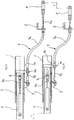
- an overrun braking device which comprises a housing 3, which is fastened in the tubular part 1.
- a pull rod 4 is guided longitudinally, which is provided at the front end with a coupling, not shown, for a towing vehicle.
- a shock absorber 5 is arranged in the pull rod 4, the housing of which is connected to the pull rod 4 by means of a bearing bolt 5a and the piston rod of which is connected to the housing 3 of the overrun braking device and possibly the tubular front part 1 of the drawbar by means of a bolt 6.
- the pull rod 4 is provided with lateral slots 4 a for the passage of the bolt 6.
- the transmission device used for this purpose consists of a Bowden cable 7, the casing 7a of which has a front end on the pull rod 4 and a rear end on the fastening bracket 2 is attached.
- the front end of the wire 7b of the Bowden cable 7 is connected to the bolt 6, which in this way represents a fixed point formed on the front part 1 of the drawbar; the rear end of the strand 7b is connected to a coupling piece 8, which in turn is connected to the front end of the brake linkage, not shown.
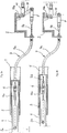
- FIGS. 2a and 2b of the second embodiment show one in this respect different version.
- the front end of the casing 7a of the Bowden cable 7 is fastened to an extension arm 4b of the pull rod 4, which projects downwards through a slot 1a from the tubular front part 1 of the drawbar.
- the front end of the strand 7b of the Bowden cable 7 is fastened to a bracket 9 which is welded to the underside of the tubular front part 1 of the drawbar.
- the actuation path X generated by the penetration of the pull rod 4 into the housing 3 of the overrun braking device results in a corresponding actuation path X of the coupling piece 8 connected to the front end of the brake linkage .
- the position of the casing 7a of the Bowden cable 7, which is fastened with its front end to the front part 1 of the drawbar and with its rear end to the fastening angle 2 of the drawbar or the vehicle frame, remains unchanged.
- the penetration movement of the pull rod 4 into the housing 3 only results in a pulling out of the front end of the strand 7b from the sheath 7a and thus pulling the coupling piece 8 over the actuation path X. This movement becomes the actuation of the braking device, not shown, of the vehicle trailer used.
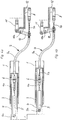
- FIGS. 3a and 3b or 4a and 4b use a transmission lever 10 to make the relative movement the tie rod 4 to the housing 3 to transfer to the brake linkage.
- such a transmission lever 10 is pivotably mounted on the mounting bracket 2, specifically by means of a bearing bolt 10a arranged at its upper end. With its lower end, the transmission lever 10 is connected to the coupling piece 8, which in turn is attached to the rear end of the strand 7b of the Bowden cable 7. With an actuation path X between the tie rod 4 and the housing 3, this results in a pivoting of the transmission lever 10 in a clockwise direction, the indicated brake linkage 11 being articulated on the transmission lever 10 between the bearing pin 10a and the coupling piece 8.
- the fourth embodiment according to FIGS. 4a and 4b differs from the third embodiment described above in that the transmission lever 10 is pivotably mounted in the central region by means of a bearing bolt 10a on the mounting bracket 2 and in that the front end of the brake linkage 11 is at the upper end of the transmission lever 10 attacks.
- the lower end of the transmission lever 10 is connected to the rear end of the sheath 7a of the Bowden cable 7, whereas the rear end of the strand 7b is fastened to a support bracket 12 by means of the coupling piece 8.
Landscapes
- Engineering & Computer Science (AREA)
- Transportation (AREA)
- Mechanical Engineering (AREA)
- Physics & Mathematics (AREA)
- Fluid Mechanics (AREA)
- Transmission Of Braking Force In Braking Systems (AREA)
- Regulating Braking Force (AREA)
- Braking Arrangements (AREA)
Applications Claiming Priority (2)
| Application Number | Priority Date | Filing Date | Title |
|---|---|---|---|
| DE19617065 | 1996-04-29 | ||
| DE19617065A DE19617065C1 (de) | 1996-04-29 | 1996-04-29 | Zugvorrichtung für Fahrzeuganhänger |
Publications (2)
| Publication Number | Publication Date |
|---|---|
| EP0805083A2 true EP0805083A2 (fr) | 1997-11-05 |
| EP0805083A3 EP0805083A3 (fr) | 1998-10-14 |
Family
ID=7792760
Family Applications (1)
| Application Number | Title | Priority Date | Filing Date |
|---|---|---|---|
| EP97104235A Withdrawn EP0805083A3 (fr) | 1996-04-29 | 1997-03-13 | Dispositif de traction pour remorque |
Country Status (6)
| Country | Link |
|---|---|
| EP (1) | EP0805083A3 (fr) |
| CZ (1) | CZ127597A3 (fr) |
| DE (1) | DE19617065C1 (fr) |
| HU (1) | HUP9700822A3 (fr) |
| PL (1) | PL319714A1 (fr) |
| SI (1) | SI9700081B (fr) |
Cited By (2)
| Publication number | Priority date | Publication date | Assignee | Title |
|---|---|---|---|---|
| EP4306371A1 (fr) * | 2022-07-11 | 2024-01-17 | Alois Kober GmbH | Dispositif de freinage |
| EP4480765A1 (fr) * | 2023-06-21 | 2024-12-25 | Croozer GmbH | Système de freinage |
Families Citing this family (1)
| Publication number | Priority date | Publication date | Assignee | Title |
|---|---|---|---|---|
| DE102017114820B4 (de) * | 2017-07-04 | 2019-06-19 | Roland Werk Gmbh | Auflaufbremse für für einen Anhänger |
Family Cites Families (4)
| Publication number | Priority date | Publication date | Assignee | Title |
|---|---|---|---|---|
| GB206213A (en) * | 1922-07-29 | 1923-10-29 | Thomas Henry Cole | Improvements in brakes |
| DE3120571A1 (de) * | 1981-05-23 | 1982-12-09 | Hahn Fahrzeugbau Gmbh, 7012 Fellbach | Auflaufbremseinrichtung mit hoehenverstellung fuer gebremste anhaenger |
| DE3523336C1 (de) * | 1985-06-29 | 1986-11-06 | Eisenwerk Grümer GmbH & Co KG, 5276 Wiehl | Feststellbremse für Fahrzeuganhänger mit Auflaufbremse |
| DE9410842U1 (de) * | 1994-07-07 | 1995-08-10 | Bernhard, Uwe, 71404 Korb | Vorrichtung zum Abbremsen, vorzugsweise eines Fahrrad-Anhängers |
-
1996
- 1996-04-29 DE DE19617065A patent/DE19617065C1/de not_active Expired - Lifetime
-
1997
- 1997-03-13 EP EP97104235A patent/EP0805083A3/fr not_active Withdrawn
- 1997-04-03 SI SI9700081A patent/SI9700081B/sl unknown
- 1997-04-28 CZ CZ971275A patent/CZ127597A3/cs unknown
- 1997-04-28 HU HU9700822A patent/HUP9700822A3/hu unknown
- 1997-04-28 PL PL97319714A patent/PL319714A1/xx unknown
Cited By (2)
| Publication number | Priority date | Publication date | Assignee | Title |
|---|---|---|---|---|
| EP4306371A1 (fr) * | 2022-07-11 | 2024-01-17 | Alois Kober GmbH | Dispositif de freinage |
| EP4480765A1 (fr) * | 2023-06-21 | 2024-12-25 | Croozer GmbH | Système de freinage |
Also Published As
| Publication number | Publication date |
|---|---|
| DE19617065C1 (de) | 1997-10-16 |
| HU9700822D0 (en) | 1997-06-30 |
| CZ127597A3 (en) | 1997-11-12 |
| HUP9700822A3 (en) | 2000-02-28 |
| SI9700081B (sl) | 1998-08-31 |
| SI9700081A (en) | 1997-12-31 |
| PL319714A1 (en) | 1997-11-10 |
| HUP9700822A2 (hu) | 1999-04-28 |
| EP0805083A3 (fr) | 1998-10-14 |
Similar Documents
| Publication | Publication Date | Title |
|---|---|---|
| EP0749891B1 (fr) | Montage de sécurité pour l'espace des pieds dans un véhicule automobile | |
| EP1380445B1 (fr) | Dispositif de traction de remorque | |
| DE19514541A1 (de) | Gaspedal mit Reibkörper | |
| EP0393211B1 (fr) | Frein à tambour pour véhicule comportant un frein de parquage | |
| EP1343662B1 (fr) | Dispositif pour le logement d'un levier de pedale dans un vehicule | |
| DE3533420A1 (de) | Anordnung zur lagerung des bremspedals | |
| DE9405849U1 (de) | Feststellbremse für Kraftfahrzeuge, Fahrzeuganhänger o.dgl. | |
| DE69502839T2 (de) | Klemmmechanismus für eine verstellbare lenksäule | |
| EP0382911A1 (fr) | Dispositif de commande d'un embrayage d'automobile | |
| DE4023047C2 (de) | Verfahren zur Montage einer vormontierten Handbremsvorrichtung | |
| EP0805083A2 (fr) | Dispositif de traction pour remorque | |
| EP0904990A1 (fr) | Unité d'actionnement | |
| DE29702064U1 (de) | Zugvorrichtung mit Auflaufbremseinrichtung für Kraftfahrzeuganhänger | |
| EP0683077A1 (fr) | Véhicule automobile ayant un levier de vitesses et un levier de frein à main au centre du véhicule | |
| EP0298471B1 (fr) | Protection anti-encastrement pour la partie arrière d'un véhicule à benne basculante ayant une structure basculable autour d'un axe transversal arrière | |
| EP0805081B1 (fr) | Dispositif de traction,réglable en hauteur,pour remorque | |
| DE69102024T2 (de) | Kraftdämpfende und zusammenschiebbare Lenksäulehalter. | |
| EP0805082B1 (fr) | Dispositif de traction pour remorque | |
| DE19636832C2 (de) | Auflaufbremsvorrichtung für Anhänger von Einspurfahrzeugen | |
| DE60100820T2 (de) | Pedalanordnung für Fahrzeuge | |
| DE19636775A1 (de) | Zweirad mit Rahmen, an diesem schwenkbarer Vorderradabel sowie Ständer | |
| DE60109852T2 (de) | Sitzeinbaustruktur für einen Kraftfahrzeug | |
| DE3408058A1 (de) | Vorrichtung zur betaetigung einer feststellbremse von kraftfahrzeugen, insbesondere nutzfahrzeugen | |
| DE29619926U1 (de) | Bremsmechanismus für Fahrräder | |
| EP0802099B1 (fr) | Frein à main et frein à inertie combinés pour remorques |
Legal Events
| Date | Code | Title | Description |
|---|---|---|---|
| PUAI | Public reference made under article 153(3) epc to a published international application that has entered the european phase |
Free format text: ORIGINAL CODE: 0009012 |
|
| AK | Designated contracting states |
Kind code of ref document: A2 Designated state(s): DE FR GB IT |
|
| PUAL | Search report despatched |
Free format text: ORIGINAL CODE: 0009013 |
|
| AK | Designated contracting states |
Kind code of ref document: A3 Designated state(s): DE FR GB IT |
|
| 17P | Request for examination filed |
Effective date: 19990107 |
|
| 17Q | First examination report despatched |
Effective date: 20000218 |
|
| STAA | Information on the status of an ep patent application or granted ep patent |
Free format text: STATUS: THE APPLICATION HAS BEEN WITHDRAWN |
|
| 18W | Application withdrawn |
Withdrawal date: 20000524 |