EP0805083A2 - Traction device for a trailer - Google Patents
Traction device for a trailer Download PDFInfo
- Publication number
- EP0805083A2 EP0805083A2 EP97104235A EP97104235A EP0805083A2 EP 0805083 A2 EP0805083 A2 EP 0805083A2 EP 97104235 A EP97104235 A EP 97104235A EP 97104235 A EP97104235 A EP 97104235A EP 0805083 A2 EP0805083 A2 EP 0805083A2
- Authority
- EP
- European Patent Office
- Prior art keywords
- drawbar
- vehicle frame
- rear end
- brake
- bowden cable
- Prior art date
- Legal status (The legal status is an assumption and is not a legal conclusion. Google has not performed a legal analysis and makes no representation as to the accuracy of the status listed.)
- Withdrawn
Links
- 230000005540 biological transmission Effects 0.000 claims abstract description 30
- 230000008878 coupling Effects 0.000 claims abstract description 12
- 238000010168 coupling process Methods 0.000 claims abstract description 12
- 238000005859 coupling reaction Methods 0.000 claims abstract description 12
- 239000006096 absorbing agent Substances 0.000 description 3
- 230000035939 shock Effects 0.000 description 3
- 230000035515 penetration Effects 0.000 description 2
- 238000010276 construction Methods 0.000 description 1
- 238000013016 damping Methods 0.000 description 1
Images

Classifications
-
- B—PERFORMING OPERATIONS; TRANSPORTING
- B60—VEHICLES IN GENERAL
- B60T—VEHICLE BRAKE CONTROL SYSTEMS OR PARTS THEREOF; BRAKE CONTROL SYSTEMS OR PARTS THEREOF, IN GENERAL; ARRANGEMENT OF BRAKING ELEMENTS ON VEHICLES IN GENERAL; PORTABLE DEVICES FOR PREVENTING UNWANTED MOVEMENT OF VEHICLES; VEHICLE MODIFICATIONS TO FACILITATE COOLING OF BRAKES
- B60T13/00—Transmitting braking action from initiating means to ultimate brake actuator with power assistance or drive; Brake systems incorporating such transmitting means, e.g. air-pressure brake systems
- B60T13/02—Transmitting braking action from initiating means to ultimate brake actuator with power assistance or drive; Brake systems incorporating such transmitting means, e.g. air-pressure brake systems with mechanical assistance or drive
- B60T13/06—Transmitting braking action from initiating means to ultimate brake actuator with power assistance or drive; Brake systems incorporating such transmitting means, e.g. air-pressure brake systems with mechanical assistance or drive by inertia, e.g. flywheel
- B60T13/08—Overrun brakes
-
- B—PERFORMING OPERATIONS; TRANSPORTING
- B60—VEHICLES IN GENERAL
- B60T—VEHICLE BRAKE CONTROL SYSTEMS OR PARTS THEREOF; BRAKE CONTROL SYSTEMS OR PARTS THEREOF, IN GENERAL; ARRANGEMENT OF BRAKING ELEMENTS ON VEHICLES IN GENERAL; PORTABLE DEVICES FOR PREVENTING UNWANTED MOVEMENT OF VEHICLES; VEHICLE MODIFICATIONS TO FACILITATE COOLING OF BRAKES
- B60T7/00—Brake-action initiating means
- B60T7/12—Brake-action initiating means for automatic initiation; for initiation not subject to will of driver or passenger
- B60T7/20—Brake-action initiating means for automatic initiation; for initiation not subject to will of driver or passenger specially for trailers, e.g. in case of uncoupling of or overrunning by trailer
Definitions
- the invention relates in particular to a height-adjustable towing device for vehicle trailers with an overrun braking device which acts on a brake linkage by means of a transmission device when there is a relative movement between a connecting rod connected to the coupling for a towing vehicle and a drawbar connected to the trailer vehicle frame.
- the transmission device comprises a deflection lever which is usually arranged in the region of the overrun braking device and which not only increases the weight of the front part of the pulling device but also restricts the ground clearance.
- the invention has for its object to develop a pulling device of the type described above such that there are no parts restricting the ground clearance and weighting the front end of the drawbar in the area of the overrun brake device arranged at the front end of the drawbar, which serves as a bearing for the drawbar .
- the transmission device is formed by a Bowden cable, the casing of which is fixed with its front end to the drawbar and with its rear end to a fixed point on the drawbar or on the trailer vehicle frame and the braid with its front End with the housing of the overrun brake device arranged at the front end of the drawbar and is connected at its rear end to the brake linkage or to a transmission lever connected to it.
- the transmission device is formed by a Bowden cable, the casing of which is fixed with its front end to the drawbar and with its rear end to a transmission lever mounted on the drawbar or on the trailer vehicle frame and connected to the brake linkage is and the wire is connected with its front end to the housing of the overrun brake device arranged at the front end of the drawbar and with its rear end to a fixed point on the drawbar or on the vehicle frame.
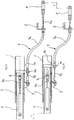
- an overrun braking device which comprises a housing 3, which is fastened in the tubular part 1.
- a pull rod 4 is guided longitudinally, which is provided at the front end with a coupling, not shown, for a towing vehicle.
- a shock absorber 5 is arranged in the pull rod 4, the housing of which is connected to the pull rod 4 by means of a bearing bolt 5a and the piston rod of which is connected to the housing 3 of the overrun braking device and possibly the tubular front part 1 of the drawbar by means of a bolt 6.
- the pull rod 4 is provided with lateral slots 4 a for the passage of the bolt 6.
- the transmission device used for this purpose consists of a Bowden cable 7, the casing 7a of which has a front end on the pull rod 4 and a rear end on the fastening bracket 2 is attached.
- the front end of the wire 7b of the Bowden cable 7 is connected to the bolt 6, which in this way represents a fixed point formed on the front part 1 of the drawbar; the rear end of the strand 7b is connected to a coupling piece 8, which in turn is connected to the front end of the brake linkage, not shown.
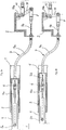
- FIGS. 2a and 2b of the second embodiment show one in this respect different version.
- the front end of the casing 7a of the Bowden cable 7 is fastened to an extension arm 4b of the pull rod 4, which projects downwards through a slot 1a from the tubular front part 1 of the drawbar.
- the front end of the strand 7b of the Bowden cable 7 is fastened to a bracket 9 which is welded to the underside of the tubular front part 1 of the drawbar.
- the actuation path X generated by the penetration of the pull rod 4 into the housing 3 of the overrun braking device results in a corresponding actuation path X of the coupling piece 8 connected to the front end of the brake linkage .
- the position of the casing 7a of the Bowden cable 7, which is fastened with its front end to the front part 1 of the drawbar and with its rear end to the fastening angle 2 of the drawbar or the vehicle frame, remains unchanged.
- the penetration movement of the pull rod 4 into the housing 3 only results in a pulling out of the front end of the strand 7b from the sheath 7a and thus pulling the coupling piece 8 over the actuation path X. This movement becomes the actuation of the braking device, not shown, of the vehicle trailer used.
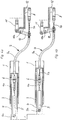
- FIGS. 3a and 3b or 4a and 4b use a transmission lever 10 to make the relative movement the tie rod 4 to the housing 3 to transfer to the brake linkage.
- such a transmission lever 10 is pivotably mounted on the mounting bracket 2, specifically by means of a bearing bolt 10a arranged at its upper end. With its lower end, the transmission lever 10 is connected to the coupling piece 8, which in turn is attached to the rear end of the strand 7b of the Bowden cable 7. With an actuation path X between the tie rod 4 and the housing 3, this results in a pivoting of the transmission lever 10 in a clockwise direction, the indicated brake linkage 11 being articulated on the transmission lever 10 between the bearing pin 10a and the coupling piece 8.
- the fourth embodiment according to FIGS. 4a and 4b differs from the third embodiment described above in that the transmission lever 10 is pivotably mounted in the central region by means of a bearing bolt 10a on the mounting bracket 2 and in that the front end of the brake linkage 11 is at the upper end of the transmission lever 10 attacks.
- the lower end of the transmission lever 10 is connected to the rear end of the sheath 7a of the Bowden cable 7, whereas the rear end of the strand 7b is fastened to a support bracket 12 by means of the coupling piece 8.
Landscapes
- Engineering & Computer Science (AREA)
- Transportation (AREA)
- Mechanical Engineering (AREA)
- Physics & Mathematics (AREA)
- Fluid Mechanics (AREA)
- Transmission Of Braking Force In Braking Systems (AREA)
- Regulating Braking Force (AREA)
- Braking Arrangements (AREA)
Abstract
Die Erfindung betrifft eine Zugvorrichtung für Fahrzeuganhänger mit einer Auflaufbremseinrichtung, die bei einer Relativbewegung zwischen einer mit der Kupplung für ein Zugfahrzeug verbundenen Zugstange (4) und einer mit dem Anhängerfahrzeugrahmen verbundenen Zugdeichsel mittels einer Übertragungseinrichtung auf ein Bremsgestänge wirkt. Die Übertragungseinrichtung wird durch einen Bowdenzug (7) gebildet, dessen Hülle mit ihrem vorderen Ende an der Zugstange (4) festgelegt und dessen Litze mit ihrem vorderen Ende mit dem Gehäuse (3) der am vorderen Ende der Zugdeichsel angeordneten Auflaufbremseinrichtung verbunden ist. Das hintere Ende der Hülle (7a) des Bowdenzuges (7) kann entweder an einem Festpunkt an der Zugdeichsel oder am Anhängerfahrzeugrahmen oder an einem an der Zugdeichsel oder am Anhängerfahrzeugrahmen gelagerten, mit dem Bremsgestänge verbundenen Übertragungshebel festgelegt sein. Das hintere Ende der Litze (7b) des Bowdenzuges (7) wird entweder mit dem Bremsgestänge bzw. mit einem mit diesem verbundenen Übersetzungshebel oder mit einem Festpunkt an der Zugdeichsel oder am Fahrzeugrahmen verbunden.
Description
Die Erfindung betrifft eine insbesondere höhenverstellbare Zugvorrichtung für Fahrzeuganhänger mit einer Auflaufbremseinrichtung, die bei einer Relativbewegung zwischen einer mit der Kupplung für ein Zugfahrzeug verbundenen Zugstange und einer mit dem Anhängerfahrzeugrahmen verbundenen Zugdeichsel mittels einer Übertragungseinrichtung auf ein Bremsgestänge wirkt.The invention relates in particular to a height-adjustable towing device for vehicle trailers with an overrun braking device which acts on a brake linkage by means of a transmission device when there is a relative movement between a connecting rod connected to the coupling for a towing vehicle and a drawbar connected to the trailer vehicle frame.
Derartige Zugvorrichtungen für Fahrzeuganhänger sind auch in höhenverstellbarer Ausführung bekannt. Die Übertragungseinrichtung umfaßt bei den bekannten Konstruktionen einen üblicherweise im Bereich der Auflaufbremseinrichtung angeordneten Umlenkhebel, der nicht nur das Gewicht des vorderen Teils der Zugvorrichtung erhöht, sondern auch die Bodenfreiheit einschränkt.Such pulling devices for vehicle trailers are also known in a height-adjustable design. In the known constructions, the transmission device comprises a deflection lever which is usually arranged in the region of the overrun braking device and which not only increases the weight of the front part of the pulling device but also restricts the ground clearance.
Der Erfindung liegt die Aufgabe zugrunde, eine Zugvorrichtung der voranstehend beschriebenen Art derart weiterzubilden, daß im Bereich der am vorderen Ende der Zugdeichsel angeordneten, als Lager für die Zugstange dienenden Auflaufbremseinrichtung keine die Bodenfreiheit einschränkenden und das vordere Ende der Zugdeichsel mit Gewicht belastenden Teile vorhanden sind.The invention has for its object to develop a pulling device of the type described above such that there are no parts restricting the ground clearance and weighting the front end of the drawbar in the area of the overrun brake device arranged at the front end of the drawbar, which serves as a bearing for the drawbar .
Die Lösung dieser Aufgabenstellung durch die Erfindung ist dadurch gekennzeichnet, daß die Übertragungseinrichtung durch einen Bowdenzug gebildet ist, dessen Hülle mit ihrem vorderen Ende an der Zugstange und mit ihrem hinteren Ende an einem Festpunkt an der Zugdeichsel oder am Anhängerfahrzeugrahmen festgelegt und dessen Litze mit ihrem vorderen Ende mit dem Gehäuse der am vorderen Ende der Zugdeichsel angeordneten Auflaufbremseinrichtung und mit ihrem hinteren Ende mit dem Bremsgestänge bzw. mit einem mit diesem verbundenen Übersetzungshebel verbunden ist.The solution to this problem by the invention is characterized in that the transmission device is formed by a Bowden cable, the casing of which is fixed with its front end to the drawbar and with its rear end to a fixed point on the drawbar or on the trailer vehicle frame and the braid with its front End with the housing of the overrun brake device arranged at the front end of the drawbar and is connected at its rear end to the brake linkage or to a transmission lever connected to it.
Eine alternative Lösung der Aufgabenstellung durch die Erfindung besteht darin, daß die Übertragungseinrichtung durch einen Bowdenzug gebildet ist, dessen Hülle mit ihrem vorderen Ende an der Zugstange und mit ihrem hinteren Ende an einem an der Zugdeichsel oder am Anhängerfahrzeugrahmen gelagerten, mit dem Bremsgestänge verbundenen Übertragungshebel festgelegt ist und dessen Litze mit ihrem vorderen Ende mit dem Gehäuse der am vorderen Ende der Zugdeichsel angeordneten Auflaufbremseinrichtung und mit ihrem hinteren Ende mit einem Festpunkt an der Zugdeichsel oder am Fahrzeugrahmen verbunden ist.An alternative solution to the problem by the invention is that the transmission device is formed by a Bowden cable, the casing of which is fixed with its front end to the drawbar and with its rear end to a transmission lever mounted on the drawbar or on the trailer vehicle frame and connected to the brake linkage is and the wire is connected with its front end to the housing of the overrun brake device arranged at the front end of the drawbar and with its rear end to a fixed point on the drawbar or on the vehicle frame.
In beiden Fällen ergibt sich eine Zugvorrichtung, bei der am vorderen Ende des Deichselrohres keine die Bodenfreiheit einschränkenden und zusätzliches Gewicht darstellenden Teile vorhanden sind.In both cases there is a pulling device in which there are no parts restricting the ground clearance and representing additional weight at the front end of the drawbar tube.
Auf der Zeichnung sind verschiedene Ausführungsbeispiele der erfindungsgemäßen Übertragungseinrichtung für eine Zugvorrichtung schematisch dargestellt, und zwar zeigen:
- Fig. 1a
- eine Seitenansicht einer ersten Ausführungsform in der Ausgangstellung,
- Fig. 1b
- eine der Fig. 1a entsprechende Seitenansicht nach Betätigen der Auflaufbremseinrichtung,
- Fig. 2a
- eine Seitenansicht einer zweiten Ausführungsform der Übertragungseinrichtung, wiederum in der Ausgangsstellung,
- Fig. 2b
- eine der Fig. 2a entsprechende Ansicht nach Betätigen der Auflaufbremseinrichtung,
- Fig. 3a
- eine Seitenansicht einer weiteren Ausführungsform der Übertragungseinrichtung in der Ausgangsstellung,
- Fig. 3b
- eine Ansicht der Übertragungseinrichtung nach Fig. 3a nach Betätigen der Auflaufbremseinrichtung,
- Fig. 4a
- eine schematische Seitenansicht einer vierten Ausführungsform der Übertragungeinrichtung in der Ausgangsstellung und
- Fig. 4b
- eine der Fig. 4a entsprechende Ansicht nach Betätigen der Auflaufbremseinrichtung.
- Fig. 1a
- a side view of a first embodiment in the starting position,
- Fig. 1b
- 1 a side view corresponding to FIG. 1 a after actuation of the overrun braking device,
- Fig. 2a
- 2 shows a side view of a second embodiment of the transmission device, again in the starting position,
- Fig. 2b
- 2 a view corresponding to FIG. 2a after actuation of the overrun braking device,
- Fig. 3a
- a side view of a further embodiment of the transmission device in the starting position,
- Fig. 3b
- 3a after actuation of the overrun braking device,
- Fig. 4a
- is a schematic side view of a fourth embodiment of the transmission device in the starting position and
- Fig. 4b
- a view corresponding to FIG. 4a after actuation of the overrun braking device.
Bei allen vier Ausführungsbeispielen ist von der Zugvorrichtung lediglich der ggf. höhenverstellbare vordere Teil 1 einer im übrigen nicht gezeichneten Zugdeichsel dargestellt, die an ihrem hinteren Ende mit dem Fahrzeugrahmen eines Fahrzeuganhängers verbunden ist. Von diesem hinteren Teil der Zugdeichsel bzw. dem Rahmen des Fahrzeuganhängers ist auf den Zeichnungen lediglich ein als Festpunkt dienender Befestigungswinkel 2 angedeutet.In all four exemplary embodiments, only the possibly height-adjustable
Im vorderen Teil 1 der Zugdeichsel ist eine Auflaufbremseinrichtung angeordnet, die ein Gehäuse 3 umfaßt, das im rohrförmigen Teil 1 befestigt ist. In diesem Gehäuse 3 ist eine Zugstange 4 längsbeweglich geführt, die am vorderen Ende mit einer nicht gezeichneten Kupplung für ein Zugfahrzeug versehen ist. In der Zugstange 4 ist ein Stoßdämpfer 5 angeordnet, dessen Gehäuse mittels eines Lagerbolzens 5a mit der Zugstange 4 und dessen Kolbenstange mittels eines Bolzens 6 mit dem Gehäuse 3 der Auflaufbremseinrichtung und ggf. dem rohrförmigen vorderen Teil 1 der Zugdeichsel verbunden ist. Um eine Relativbewegung der Zugstange 4 im Verhältnis zum Gehäuse 3 zu ermöglichen, ist die Zugstange 4 für den Durchtritt des Bolzens 6 mit seitlichen Schlitzen 4a versehen.In the
Da beim Abbremsen des Zugfahrzeuges das Anhängerfahrzeug aufgrund seiner Massenträgheit eine vom Stoßdämpfer 5 gedämpfte Relativbewegung des am vorderen Teil 1 der Zugdeichsel befestigten Gehäuses 3 relativ zur Zugstange 4 hervorruf, wird der in den Fig. 1a und 1b eingetragene Betätigungsweg X zur Erzielung der Bremswirkung auf ein Bremsgestänge der Bremse des Fahrzeuganhängers übertragen. Die hierfür verwendete Übertragungseinrichtung besteht aus einem Bowdenzug 7, dessen Hülle 7a mit ihrem vorderen Ende an der Zugstange 4 und mit ihrem hinteren Ende am Befestigungswinkel 2 befestigt ist. Die Litze 7b des Bowdenzuges 7 ist mit ihrem vorderen Ende mit dem Bolzen 6 verbunden, der auf diese Weise einen am vorderen Teil 1 der Zugdeichsel ausgebildeten Fixpunkt darstellt; das hintere Ende der Litze 7b ist mit einem Kupplungsstück 8 verbunden, das seinerseits mit dem vorderen Ende des nicht dargestellten Bremsgestänges verbunden wird.Since, when the towing vehicle brakes, the trailer vehicle, due to its inertia, causes a damping of the
Während beim ersten Ausführungsbeispiel nach den Fig. 1a und 1b das vordere Ende der Litze 7b unmittelbar am Bolzen 6 und das vordere Ende der Hülle 7a an der hinteren Stirnfläche der Zugstange 4 festgelegt sind, zeigen die Fig. 2a und 2b des zweiten Ausführungsbeispiels insoweit eine abweichende Ausführung. Bei dieser zweiten Ausführungsform ist das vordere Ende der Hülle 7a des Bowdenzuges 7 an einem Ausleger 4b der Zugstange 4 befestigt, der durch einen Schlitz 1a nach unten aus dem rohrförmigen vorderen Teil 1 der Zugdeichsel herausragt. Das vordere Ende der Litze 7b des Bowdenzuges 7 ist bei dieser Ausführungsform an einer Konsole 9 befestigt, die an die Unterseite des rohrförmigen vorderen Teils 1 der Zugdeichsel angeschweißt ist.While the first embodiment according to FIGS. 1a and 1b fixes the front end of the
Wie aus einem Vergleich der Fig. 1a und 1b bzw. 2a und 2b hervorgeht, hat der durch das Eindringen der Zugstange 4 in das Gehäuse 3 der Auflaufbremseinrichtung erzeugte Betätigungsweg X einen entsprechenden Betätigungsweg X des mit dem vorderen Ende des Bremsgestänges verbundenen Kupplungsstückes 8 zur Folge. Die Lage der mit ihrem vorderen Ende am vorderen Teil 1 der Zugdeichsel und mit ihrem hinteren Ende am Befestigungswinkel 2 der Zugdeichsel bzw. des Fahrzeugrahmens befestigten Hülle 7a des Bowdenzuges 7 bleibt hierbei unverändert. Die Eindringbewegung der Zugstange 4 in das Gehäuse 3 hat lediglich ein Herausziehen des vorderen Endes der Litze 7b aus der Hülle 7a nach vorn zur Folge und damit ein Ziehen des Kupplungsstückes 8 über den Betätigungsweg X. Diese Bewegung wird zur Betätigung der nicht dargestellten Bremseinrichtung des Fahrzeuganhängers herangezogen.As can be seen from a comparison of FIGS. 1a and 1b or 2a and 2b, the actuation path X generated by the penetration of the
Die in den Fig. 3a und 3b bzw. 4a und 4b gezeichneten weiteren Ausführungsbeispiele verwenden einen Übersetzungshebel 10, um die Relativbewegung der Zugstange 4 gegenüber dem Gehäuse 3 auf das Bremsgestänge zu übertragen.The further exemplary embodiments shown in FIGS. 3a and 3b or 4a and 4b use a
Beim Ausführungsbeispiel nach den Fig. 3a und 3b ist ein derartiger Übersetzungshebel 10 am Befestigungswinkel 2 verschwenkbar gelagert, und zwar mittels eines an seinem oberen Ende angeordneten Lagerbolzens 10a. Mit seinem unteren Ende ist der Übersetzungshebel 10 mit dem Kupplungsstück 8 verbunden, das wiederum am hinteren Ende der Litze 7b des Bowdenzuges 7 befestigt ist. Bei einem Betätigungsweg X zwischen Zugstange 4 und Gehäuse 3 ergibt sich auf diese Weise eine Verschwenkung des Übersetzungshebels 10 im Uhrzeigersinn, wobei das angedeutete Bremsgestänge 11 am Übersetzungshebel 10 zwischen dem Lagerbolzen 10a und dem Kupplungsstück 8 angelenkt ist.In the embodiment according to FIGS. 3a and 3b, such a
Die vierte Ausführungsform nach den Fig. 4a und 4b unterscheidet sich von der voranstehend beschriebenen dritten Ausführungsform dadurch, daß der Übersetzungshebel 10 im mittleren Bereich mittels eines Lagerbolzens 10a am Befestigungswinkel 2 verschwenkbar gelagert ist und daß das vordere Ende des Bremsgestänges 11 am oberen Ende des Übersetzungshebels 10 angreift. Das untere Ende des Übersetzungshebels 10 ist mit dem hinteren Ende der Hülle 7a des Bowdenzuges 7 verbunden, wogegen das hintere Ende der Litze 7b mittels des Kupplungsstückes 8 an einer Tragkonsole 12 befestigt ist. Auch bei dieser Ausführungsform ergibt sich eine Verschwenkbewegung des Übersetzungshebels 10, allerdings im Gegenuhrzeigersinn, die zu einer ziehenden Betätigung des Bremsgestänges 11 führt.The fourth embodiment according to FIGS. 4a and 4b differs from the third embodiment described above in that the
- 11
- vorderer Teil der Zugdeichselfront part of the drawbar
- 1a1a
- Schlitzslot
- 22nd
- Befestigungswinkelmounting brackets
- 33rd
- Gehäusecasing
- 44th
- Zugstangepull bar
- 4a4a
- Schlitzslot
- 4b4b
- Auslegerboom
- 55
- StoßdämpferShock absorber
- 5a5a
- LagerbolzenBearing bolt
- 66
- Bolzenbolt
- 77
- BowdenzugBowden cable
- 7a7a
- HülleCover
- 7b7b
- LitzeStrand
- 88th
- KupplungsstückCoupling piece
- 99
- Konsoleconsole
- 1010th
- ÜbersetzungshebelTranslation lever
- 10a10a
- LagerbolzenBearing bolt
- 1111
- BremsgestängeBrake linkage
- 1212th
- TragkonsoleSupport bracket
Claims (2)
dadurch gekennzeichnet,
daß die Übertragungseinrichtung durch einen Bowdenzug (7) gebildet ist, dessen Hülle (7a) mit ihrem vorderen Ende an der Zugstange (4) und mit ihrem hinteren Ende an einem Festpunkt (2) an der Zugdeichsel oder am Anhängerfahrzeugrahmen festgelegt ist und dessen Litze (7b) mit ihrem vorderen Ende mit dem Gehäuse (3) der am vorderen Ende der Zugdeichsel angeordneten Auflaufbremseinrichtung und mit ihrem hinteren Ende mit dem Bremsgestänge bzw. mit einem mit diesem verbundenen Übersetzungshebel (10) verbunden ist.Towing device for vehicle trailers with an overrun brake device which acts on a brake linkage by means of a transmission device when there is a relative movement between a drawbar connected to the coupling for a towing vehicle and a drawbar connected to the trailer vehicle frame,
characterized,
that the transmission device is formed by a Bowden cable (7), the casing (7a) of which is fixed with its front end to the drawbar (4) and with its rear end to a fixed point (2) on the drawbar or on the trailer vehicle frame and the stranded wire ( 7b) is connected at its front end to the housing (3) of the overrun brake device arranged at the front end of the drawbar and at its rear end to the brake linkage or to a transmission lever (10) connected to it.
dadurch gekennzeichnet,
daß die Übertragungseinrichtung durch einen Bowdenzug (7) gebildet ist, dessen Hülle (7a) mit ihrem vorderen Ende an der Zugstange (4) und mit ihrem hinteren Ende an einem an der Zugdeichsel oder am Anhängerfahrzeugrahmen gelagerten, mit dem Bremsgestänge (11) verbundenen Übersetzungshebel (10) festgelegt ist und dessen Litze (7b) mit ihrem vorderen Ende mit dem Gehäuse (3) der am vorderen Ende (1) der Zugdeichsel angeordneten Auflaufbremseinrichtung und mit ihrem hinteren Ende mit einem Festpunkt an der Zugdeichsel oder am Fahrzeugrahmen verbunden ist.Towing device for vehicle trailers with an overrun braking device which acts on a brake linkage by means of a transmission device when there is a relative movement between a connecting rod connected to the coupling for a towing vehicle and a drawbar connected to the trailer vehicle frame,
characterized,
that the transmission device is formed by a Bowden cable (7), the casing (7a) of which is connected with its front end to the drawbar (4) and with its rear end to a transmission lever mounted on the drawbar or on the trailer vehicle frame and connected to the brake linkage (11) (10) is fixed and the strand (7b) is connected with its front end to the housing (3) of the overrun brake device arranged at the front end (1) of the drawbar and with its rear end to a fixed point on the drawbar or on the vehicle frame.
Applications Claiming Priority (2)
| Application Number | Priority Date | Filing Date | Title |
|---|---|---|---|
| DE19617065 | 1996-04-29 | ||
| DE19617065A DE19617065C1 (en) | 1996-04-29 | 1996-04-29 | Towing device for vehicle trailers |
Publications (2)
| Publication Number | Publication Date |
|---|---|
| EP0805083A2 true EP0805083A2 (en) | 1997-11-05 |
| EP0805083A3 EP0805083A3 (en) | 1998-10-14 |
Family
ID=7792760
Family Applications (1)
| Application Number | Title | Priority Date | Filing Date |
|---|---|---|---|
| EP97104235A Withdrawn EP0805083A3 (en) | 1996-04-29 | 1997-03-13 | Traction device for a trailer |
Country Status (6)
| Country | Link |
|---|---|
| EP (1) | EP0805083A3 (en) |
| CZ (1) | CZ127597A3 (en) |
| DE (1) | DE19617065C1 (en) |
| HU (1) | HUP9700822A3 (en) |
| PL (1) | PL319714A1 (en) |
| SI (1) | SI9700081B (en) |
Cited By (2)
| Publication number | Priority date | Publication date | Assignee | Title |
|---|---|---|---|---|
| EP4306371A1 (en) * | 2022-07-11 | 2024-01-17 | Alois Kober GmbH | Braking device |
| EP4480765A1 (en) * | 2023-06-21 | 2024-12-25 | Croozer GmbH | Braking system |
Families Citing this family (1)
| Publication number | Priority date | Publication date | Assignee | Title |
|---|---|---|---|---|
| DE102017114820B4 (en) * | 2017-07-04 | 2019-06-19 | Roland Werk Gmbh | Overrun brake for a trailer |
Family Cites Families (4)
| Publication number | Priority date | Publication date | Assignee | Title |
|---|---|---|---|---|
| GB206213A (en) * | 1922-07-29 | 1923-10-29 | Thomas Henry Cole | Improvements in brakes |
| DE3120571A1 (en) * | 1981-05-23 | 1982-12-09 | Hahn Fahrzeugbau Gmbh, 7012 Fellbach | Overrun brake device with height adjustment for braked trailers |
| DE3523336C1 (en) * | 1985-06-29 | 1986-11-06 | Eisenwerk Grümer GmbH & Co KG, 5276 Wiehl | Parking brake for vehicle trailer with overrun brake |
| DE9410842U1 (en) * | 1994-07-07 | 1995-08-10 | Bernhard, Uwe, 71404 Korb | Device for braking, preferably a bicycle trailer |
-
1996
- 1996-04-29 DE DE19617065A patent/DE19617065C1/en not_active Expired - Lifetime
-
1997
- 1997-03-13 EP EP97104235A patent/EP0805083A3/en not_active Withdrawn
- 1997-04-03 SI SI9700081A patent/SI9700081B/en unknown
- 1997-04-28 CZ CZ971275A patent/CZ127597A3/en unknown
- 1997-04-28 HU HU9700822A patent/HUP9700822A3/en unknown
- 1997-04-28 PL PL97319714A patent/PL319714A1/en unknown
Cited By (2)
| Publication number | Priority date | Publication date | Assignee | Title |
|---|---|---|---|---|
| EP4306371A1 (en) * | 2022-07-11 | 2024-01-17 | Alois Kober GmbH | Braking device |
| EP4480765A1 (en) * | 2023-06-21 | 2024-12-25 | Croozer GmbH | Braking system |
Also Published As
| Publication number | Publication date |
|---|---|
| DE19617065C1 (en) | 1997-10-16 |
| HU9700822D0 (en) | 1997-06-30 |
| CZ127597A3 (en) | 1997-11-12 |
| HUP9700822A3 (en) | 2000-02-28 |
| SI9700081B (en) | 1998-08-31 |
| SI9700081A (en) | 1997-12-31 |
| PL319714A1 (en) | 1997-11-10 |
| HUP9700822A2 (en) | 1999-04-28 |
| EP0805083A3 (en) | 1998-10-14 |
Similar Documents
| Publication | Publication Date | Title |
|---|---|---|
| EP0749891B1 (en) | Security arrangement in motor vehicle footwells | |
| EP1380445B1 (en) | Trailer traction device | |
| DE19514541A1 (en) | Accelerator pedal with friction body | |
| EP0393211B1 (en) | Drum brake for a motor vehicle, comprising a parking brake | |
| EP1343662B1 (en) | Device for mounting a pedal lever of a motor vehicle | |
| DE3533420A1 (en) | ARRANGEMENT FOR STORING THE BRAKE PEDAL | |
| DE9405849U1 (en) | Parking brake for motor vehicles, vehicle trailers or the like. | |
| DE69502839T2 (en) | CLAMPING MECHANISM FOR AN ADJUSTABLE STEERING COLUMN | |
| EP0382911A1 (en) | Actuation device for a motor vehicle clutch | |
| DE4023047C2 (en) | Method for assembling a pre-assembled handbrake device | |
| EP0805083A2 (en) | Traction device for a trailer | |
| EP0904990A1 (en) | Actuating unit | |
| DE29702064U1 (en) | Traction device with overrun braking device for motor vehicle trailers | |
| EP0683077A1 (en) | Motor vehicle with a gear lever and a handbrake lever in the centre of the vehicle | |
| EP0298471B1 (en) | Under ride protection for the rearward end of a tipper vehicle with a superstructure tippable about a rearward lateral axis | |
| EP0805081B1 (en) | Traction device,adjustable in height,for trailer | |
| DE69102024T2 (en) | Power-damping and collapsible steering column holder. | |
| EP0805082B1 (en) | Traction device for a trailer | |
| DE19636832C2 (en) | Overrun braking device for trailers of single-track vehicles | |
| DE60100820T2 (en) | Pedal assembly for vehicles | |
| DE19636775A1 (en) | Bicycle fitted with support stand | |
| DE60109852T2 (en) | Seat installation structure for a motor vehicle | |
| DE3408058A1 (en) | Device for the operation of a parking brake of motor vehicles, especially commercial vehicles | |
| DE29619926U1 (en) | Brake mechanism for bicycles | |
| EP0802099B1 (en) | Combined hand and overrunning brake for trailers |
Legal Events
| Date | Code | Title | Description |
|---|---|---|---|
| PUAI | Public reference made under article 153(3) epc to a published international application that has entered the european phase |
Free format text: ORIGINAL CODE: 0009012 |
|
| AK | Designated contracting states |
Kind code of ref document: A2 Designated state(s): DE FR GB IT |
|
| PUAL | Search report despatched |
Free format text: ORIGINAL CODE: 0009013 |
|
| AK | Designated contracting states |
Kind code of ref document: A3 Designated state(s): DE FR GB IT |
|
| 17P | Request for examination filed |
Effective date: 19990107 |
|
| 17Q | First examination report despatched |
Effective date: 20000218 |
|
| STAA | Information on the status of an ep patent application or granted ep patent |
Free format text: STATUS: THE APPLICATION HAS BEEN WITHDRAWN |
|
| 18W | Application withdrawn |
Withdrawal date: 20000524 |