EP0805035B1 - Plate-forme ombilicale amovible pour tête d'impression à jet d'encre continu - Google Patents
Plate-forme ombilicale amovible pour tête d'impression à jet d'encre continu Download PDFInfo
- Publication number
- EP0805035B1 EP0805035B1 EP19970302689 EP97302689A EP0805035B1 EP 0805035 B1 EP0805035 B1 EP 0805035B1 EP 19970302689 EP19970302689 EP 19970302689 EP 97302689 A EP97302689 A EP 97302689A EP 0805035 B1 EP0805035 B1 EP 0805035B1
- Authority
- EP
- European Patent Office
- Prior art keywords
- ink jet
- umbilical
- jet printhead
- printhead
- rigid
- Prior art date
- Legal status (The legal status is an assumption and is not a legal conclusion. Google has not performed a legal analysis and makes no representation as to the accuracy of the status listed.)
- Expired - Lifetime
Links
- 238000007641 inkjet printing Methods 0.000 description 7
- 239000012530 fluid Substances 0.000 description 6
- 238000007639 printing Methods 0.000 description 6
- 238000000429 assembly Methods 0.000 description 1
- 230000000712 assembly Effects 0.000 description 1
- 238000000151 deposition Methods 0.000 description 1
- 238000009434 installation Methods 0.000 description 1
- 238000000034 method Methods 0.000 description 1
- 238000012986 modification Methods 0.000 description 1
- 230000004048 modification Effects 0.000 description 1
Images
Classifications
-
- B—PERFORMING OPERATIONS; TRANSPORTING
- B41—PRINTING; LINING MACHINES; TYPEWRITERS; STAMPS
- B41J—TYPEWRITERS; SELECTIVE PRINTING MECHANISMS, i.e. MECHANISMS PRINTING OTHERWISE THAN FROM A FORME; CORRECTION OF TYPOGRAPHICAL ERRORS
- B41J2/00—Typewriters or selective printing mechanisms characterised by the printing or marking process for which they are designed
- B41J2/005—Typewriters or selective printing mechanisms characterised by the printing or marking process for which they are designed characterised by bringing liquid or particles selectively into contact with a printing material
- B41J2/01—Ink jet
- B41J2/17—Ink jet characterised by ink handling
- B41J2/175—Ink supply systems ; Circuit parts therefor
Definitions
- the present invention relates to continuous ink jet printing and, more particularly, to an attachable and detachable umbilical cap that facilitates ink, power, air, data and registration for a continuous ink jet printhead and printing system.
- Ink jet printing systems are known in which a printhead defines one or more rows of orifices which receive an electrically conductive recording fluid from a pressurized fluid supply manifold and eject the fluid in rows of parallel streams.
- Printers using such printheads accomplish graphic reproduction by selectively charging and deflecting the drops in each of the streams and depositing at least some of the drops on a print receiving medium, while others of the drops strike a drop catcher device.
- Continuous ink jet printing systems include an umbilical that supplies fluid (ink), air, power, and data to the printhead.
- installation of the umbilical has been a difficult and tedious process, comprised of a complex weldment with precision machined features that contributed little to assembling of the hardware.
- the umbilical has typically had many lines, cables, and connectors.
- the printhead housing cap and spine i.e., ink jet printhead support
- the printhead housing cap and spine i.e., ink jet printhead support
- cables become twisted, connectors get caught on other features, and various elements end up out of position. After component parts from the printing assembly were assembled to the spine, disassembly was almost impossible without damaging the hardware.
- a system for linking an umbilical to a continuous ink jet printhead comprising:
- the rigid printhead housing cap serves as a platform in that it serves as an attachment/detachment point for the umbilical, covers, and structural elements of a continuous ink jet printhead.
- the umbilical is easily attachable/detachable by separating the printhead housing cap from the ink jet printhead support structure, and threading the umbilical into or out of the rigid printhead housing cap.
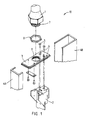
- Fig. 1 is an exploded view of an ink jet printhead structure illustrating alignment between the ink jet printhead support structure and the umbilical, in accordance with the present invention.
- a device in a continuous ink jet printing system that will serve as a rigid link between the umbilical 1 that supplies fluid (ink), air, power, and data to a continuous ink jet printhead (not shown) and the support structure 2 which supports the printhead and receives the fluid, air, power and data.
- the air provided a rigid ink jet printhead housing cap and umbilical platform 3.
- the rigid member 3 is located between the ink jet printhead support structure 2 and the umbilical 1.
- the rigid member 3 operates as a "cap” or lid for the structure 2, and as a platform under the umbilical 1.
- the umbilical 3 has a threaded end portion 7.
- the umbilical is easily attached/detached by separating the rigid member 3 from the support structure 2 and threading the umbilical end portion 7 into or out of receiving means or threaded aperture 9 of the rigid member 3.
- a locking means such as a nut 8 can be placed between the threaded end portion 7 and the rigid member 3 as umbilical 1 is attached to member 3, to lock the umbilical 1 to the rigid member 3.
- the support structure 2 can also be easily attached/detached from the umbilical and rigid member assembly by removing attachment means, such as screws 5. Hence, the umbilical 1 is threaded into the top of rigid member 3, and the support structure 2 is screwed onto the bottom of rigid member 3.
- the umbilical 1 and the rigid platform 3 can be built as a module, thereby eliminating twisting of components.
- the support structure 2 and all of its related hardware can also be built as a module.
- Final assembly then, merely comprises placing both assemblies together via self-locating features, and fastening the modules with attachment means 5.
- Built-in registration features in the rigid plate 3 accurately align the support structure 2. This insures transference of position of everything that mounts on the support structure 2 to the rigid platform 3.
- Covers 4A and 4B then enclose the entire linkage apparatus 10.
- Built-in alignment features also automatically locate and properly position the covers 4A and 4B.
- Fig. 1 The self-locating or built-in features can be seen in Fig. 1 as naturally occurring features of tongue-and-groove, lap joining, and pin-in-hole. These naturally occurring features are the keys that locate all of the separate pieces together, without resorting to complex weldment. With the loose hardware precisely located together from printhead to rigid platform 3, tolerances involving the continuous ink jet printhead are known at remote mount holes 6. Hardware that is modular and self-locating is easier to fabricate, inspect, assemble, and is more cost effective, functional, and reliable.
- the present invention is useful in the field of ink jet printing, and has the advantage of providing an optimum connection between a printing system umbilical and the structure that supports an ink jet printhead.
- the present invention provides the further advantage of providing a platform that serves as an attachment/detachment point for the umbilical, covers, and structural elements of a continuous ink jet printing system.
- the attachable/detachable umbilical platform facilitates ink, power, air, and data transference, and registration of a continuous ink jet printhead and printing system.
Landscapes
- Ink Jet (AREA)
- Particle Formation And Scattering Control In Inkjet Printers (AREA)
- Common Mechanisms (AREA)
Claims (7)
- Système de liaison d'une pièce ombilicale sur une tête d'impression à jet d'encre en continu, comprenant :une structure de support de tête d'impression à jet d'encre (2) pour supporter la tête d'impression à jet d'encre ;un capuchon rigide de logement de tête d'impression (3) placé entre la structure de support de tête d'impression à jet d'encre (2) et la pièce ombilicale ;des moyens de fixation/libération pour fixer/libérer la structure de support de tête d'impression à jet d'encre (2) sur/à partir du capuchon rigide de logement de tête d'impression (3) ; etun moyen de réception (9) associé au capuchon rigide de logement de tête d'impression (3) pour recevoir la pièce ombilicale (1), la pièce ombilicale (1) pouvant ainsi être vissée et dévissée du moyen de réception (9) du capuchon rigide de logement de tête d'impression (3).
- Système de liaison d'une pièce ombilicale sur une tête d'impression à jet d'encre en continu selon la revendication 1, dans lequel les moyens de fixation comprennent au moins une vis (5).
- Système de liaison d'une pièce ombilicale sur une tête d'impression à jet d'encre en continu selon la revendication 1, dans lequel le moyen de réception comprend une ouverture taraudée (9) traversant le capuchon rigide de logement de tête d'impression (3).
- Système de liaison d'une pièce ombilicale sur une tête d'impression à jet d'encre en continu selon la revendication 1, comprenant, de plus, des premiers dispositifs intégrés de repérage dans le capuchon rigide de logement de tête d'impression (3) pour un alignement précis avec la structure de support de tête d'impression à jet d'encre (2).
- Système de liaison d'une pièce ombilicale sur une tête d'impression à jet d'encre en continu selon la revendication 1, comprenant, de plus, des moyens de fermeture (4A, 4B) pour fermer le système de liaison.
- Système de liaison d'une pièce ombilicale sur une tête d'impression à jet d'encre en continu selon la revendication 5, comprenant, de plus, des seconds dispositifs intégrés de repérage pour localiser, de façon automatique, et pour positionner, de façon correcte, les moyens de fermeture (4A, 4B).
- Système de liaison d'une pièce ombilicale sur une tête d'impression à jet d'encre en continu selon la revendication 1, comprenant, de plus, des dispositifs à auto-positionnement pour aligner, de façon correcte, la pièce ombilicale (1) et le capuchon rigide de logement de tête d'impression (3) avec la structure de support de tête d'impression à jet d'encre (2).
Applications Claiming Priority (2)
| Application Number | Priority Date | Filing Date | Title |
|---|---|---|---|
| US64023896A | 1996-04-30 | 1996-04-30 | |
| US640238 | 1996-04-30 |
Publications (3)
| Publication Number | Publication Date |
|---|---|
| EP0805035A2 EP0805035A2 (fr) | 1997-11-05 |
| EP0805035A3 EP0805035A3 (fr) | 1997-11-12 |
| EP0805035B1 true EP0805035B1 (fr) | 2001-06-06 |
Family
ID=24567412
Family Applications (1)
| Application Number | Title | Priority Date | Filing Date |
|---|---|---|---|
| EP19970302689 Expired - Lifetime EP0805035B1 (fr) | 1996-04-30 | 1997-04-21 | Plate-forme ombilicale amovible pour tête d'impression à jet d'encre continu |
Country Status (4)
| Country | Link |
|---|---|
| EP (1) | EP0805035B1 (fr) |
| JP (1) | JPH1034908A (fr) |
| CA (1) | CA2203846A1 (fr) |
| DE (1) | DE69705089T2 (fr) |
Families Citing this family (2)
| Publication number | Priority date | Publication date | Assignee | Title |
|---|---|---|---|---|
| FR2837421B1 (fr) | 2002-03-22 | 2004-07-02 | Imaje Sa | Raccord hydro-electrique pour tete d'imprimante et imprimante equipee |
| GB0802349D0 (en) * | 2008-02-08 | 2008-03-12 | Domino Printing Sciences Plc | Improvements in or relatign to continuous inkjet printers |
Family Cites Families (9)
| Publication number | Priority date | Publication date | Assignee | Title |
|---|---|---|---|---|
| GB2060278B (en) * | 1979-10-05 | 1983-04-13 | Victor Products Ltd | Gland for metal sheathed cable |
| US4593940A (en) * | 1983-04-29 | 1986-06-10 | Wilder Don R | Flange assembly for hydraulic power systems |
| GB8622196D0 (en) * | 1986-09-15 | 1986-10-22 | Domino Printing Sciences Plc | Ink jet marking apparatus |
| US4769658A (en) * | 1986-09-16 | 1988-09-06 | Matsushita Electric Industrial Co., Ltd. | Ink jet recording apparatus with pressure adjustable mechanisms for discharging a constant ink amount |
| DE3730686A1 (de) * | 1987-09-12 | 1989-03-23 | Lapp Kg U I | Kabelverschraubung |
| US4872641A (en) * | 1988-07-22 | 1989-10-10 | Life Support Products, Inc. | Gas pressure regulator mounting yoke |
| DE4002244C1 (fr) * | 1990-01-26 | 1991-05-08 | Abs Pumpen Ag, 5204 Lohmar, De | |
| DE69327209T2 (de) * | 1992-09-02 | 2000-07-27 | Canon K.K., Tokio/Tokyo | Farbstrahlgerät mit Rückgewinnungsvorrichtung |
| DE4300521A1 (de) * | 1993-01-12 | 1994-07-14 | Weidmueller Interface | Kabelabdichtungs- und Zugentlastungsvorrichtung für Wanddurchbrüche |
-
1997
- 1997-04-21 EP EP19970302689 patent/EP0805035B1/fr not_active Expired - Lifetime
- 1997-04-21 DE DE1997605089 patent/DE69705089T2/de not_active Expired - Lifetime
- 1997-04-28 CA CA 2203846 patent/CA2203846A1/fr not_active Abandoned
- 1997-04-30 JP JP11238697A patent/JPH1034908A/ja active Pending
Also Published As
| Publication number | Publication date |
|---|---|
| EP0805035A3 (fr) | 1997-11-12 |
| AU714357B2 (en) | 1999-12-23 |
| AU1993497A (en) | 1997-11-06 |
| CA2203846A1 (fr) | 1997-10-30 |
| JPH1034908A (ja) | 1998-02-10 |
| DE69705089D1 (de) | 2001-07-12 |
| DE69705089T2 (de) | 2001-09-20 |
| EP0805035A2 (fr) | 1997-11-05 |
Similar Documents
| Publication | Publication Date | Title |
|---|---|---|
| US4559543A (en) | Ink jet recording device modular frame | |
| EP0571786B1 (fr) | Imprimante par jet d'encre en continu avec dispositif d'alignement pour les éléments de la tête d'impression | |
| US4628332A (en) | Ink printhead with holder mount | |
| EP0622240B1 (fr) | Chariot modulaire pour imprimante par jet d'encre | |
| US5969776A (en) | Display device and method of assembly | |
| CA2212266A1 (fr) | Tete d'imprimante a jet d'encre, cartouche de tete d'imprimante a jet d'encre et imprimante a jet d'encre | |
| JPH06340064A (ja) | 単一相互接続システム | |
| EP0805035B1 (fr) | Plate-forme ombilicale amovible pour tête d'impression à jet d'encre continu | |
| WO1989008561A1 (fr) | Imprimante a jet d'encre continu dotee d'un ensemble a tete d'impression modulaire | |
| EP0813974A3 (fr) | Tête d'impression par jet d'encre continu | |
| EP0805031B1 (fr) | Moyens pour positionner un assemblage de paupière à une tête d'une imprimante à jet d'encre continu | |
| US5825401A (en) | Slide in formatter for image forming devices | |
| US5739830A (en) | Monolithic printheads for ink jet printing apparatus | |
| EP0741040B1 (fr) | Collecteur de brouillard d'encre avec un fond poreux | |
| JP3697010B2 (ja) | 電子写真装置のモジュール連結構造 | |
| AU714036B2 (en) | Tool-less printhead mount | |
| JP2002159117A (ja) | 信号及び電力経路供給装置及び方法 | |
| JP3382445B2 (ja) | 画像記録装置への記録ヘッドユニット固定方法および画像記録装置 | |
| JPH0752377A (ja) | インクジェット記録装置 | |
| US6715857B2 (en) | Printhead carrier housing and flexible printed circuit attached to same | |
| EP1013458B1 (fr) | Chassis d' impression à jet d' encre monolithique | |
| CN223451348U (zh) | 应用无人机的分段式线缆结构 | |
| CN222973050U (zh) | 一种小票打印机的装配结构及电子设备 | |
| JPS61125849A (ja) | 液体噴射記録装置 | |
| JP4078925B2 (ja) | インクジェットヘッド |
Legal Events
| Date | Code | Title | Description |
|---|---|---|---|
| PUAI | Public reference made under article 153(3) epc to a published international application that has entered the european phase |
Free format text: ORIGINAL CODE: 0009012 |
|
| PUAL | Search report despatched |
Free format text: ORIGINAL CODE: 0009013 |
|
| AK | Designated contracting states |
Kind code of ref document: A2 Designated state(s): DE FR GB |
|
| AK | Designated contracting states |
Kind code of ref document: A3 Designated state(s): DE FR GB |
|
| 17P | Request for examination filed |
Effective date: 19971208 |
|
| 17Q | First examination report despatched |
Effective date: 19990702 |
|
| GRAG | Despatch of communication of intention to grant |
Free format text: ORIGINAL CODE: EPIDOS AGRA |
|
| GRAG | Despatch of communication of intention to grant |
Free format text: ORIGINAL CODE: EPIDOS AGRA |
|
| GRAH | Despatch of communication of intention to grant a patent |
Free format text: ORIGINAL CODE: EPIDOS IGRA |
|
| GRAH | Despatch of communication of intention to grant a patent |
Free format text: ORIGINAL CODE: EPIDOS IGRA |
|
| GRAA | (expected) grant |
Free format text: ORIGINAL CODE: 0009210 |
|
| AK | Designated contracting states |
Kind code of ref document: B1 Designated state(s): DE FR GB |
|
| REF | Corresponds to: |
Ref document number: 69705089 Country of ref document: DE Date of ref document: 20010712 |
|
| ET | Fr: translation filed | ||
| REG | Reference to a national code |
Ref country code: GB Ref legal event code: IF02 |
|
| PLBE | No opposition filed within time limit |
Free format text: ORIGINAL CODE: 0009261 |
|
| STAA | Information on the status of an ep patent application or granted ep patent |
Free format text: STATUS: NO OPPOSITION FILED WITHIN TIME LIMIT |
|
| 26N | No opposition filed | ||
| REG | Reference to a national code |
Ref country code: GB Ref legal event code: 732E |
|
| REG | Reference to a national code |
Ref country code: FR Ref legal event code: TP |
|
| PGFP | Annual fee paid to national office [announced via postgrant information from national office to epo] |
Ref country code: GB Payment date: 20050314 Year of fee payment: 9 |
|
| PGFP | Annual fee paid to national office [announced via postgrant information from national office to epo] |
Ref country code: FR Payment date: 20050401 Year of fee payment: 9 |
|
| PGFP | Annual fee paid to national office [announced via postgrant information from national office to epo] |
Ref country code: DE Payment date: 20050429 Year of fee payment: 9 |
|
| PG25 | Lapsed in a contracting state [announced via postgrant information from national office to epo] |
Ref country code: DE Free format text: LAPSE BECAUSE OF THE APPLICANT RENOUNCES Effective date: 20060221 |
|
| PG25 | Lapsed in a contracting state [announced via postgrant information from national office to epo] |
Ref country code: GB Free format text: LAPSE BECAUSE OF NON-PAYMENT OF DUE FEES Effective date: 20060421 |
|
| GBPC | Gb: european patent ceased through non-payment of renewal fee |
Effective date: 20060421 |
|
| REG | Reference to a national code |
Ref country code: FR Ref legal event code: ST Effective date: 20061230 |
|
| PG25 | Lapsed in a contracting state [announced via postgrant information from national office to epo] |
Ref country code: FR Free format text: LAPSE BECAUSE OF NON-PAYMENT OF DUE FEES Effective date: 20060502 |