EP0805034B1 - Tintensperre für eine Unter- oder Überdruckleitung an einem Tintenbehälter - Google Patents
Tintensperre für eine Unter- oder Überdruckleitung an einem Tintenbehälter Download PDFInfo
- Publication number
- EP0805034B1 EP0805034B1 EP97300822A EP97300822A EP0805034B1 EP 0805034 B1 EP0805034 B1 EP 0805034B1 EP 97300822 A EP97300822 A EP 97300822A EP 97300822 A EP97300822 A EP 97300822A EP 0805034 B1 EP0805034 B1 EP 0805034B1
- Authority
- EP
- European Patent Office
- Prior art keywords
- printhead
- ink
- reservoir
- vent
- tube
- Prior art date
- Legal status (The legal status is an assumption and is not a legal conclusion. Google has not performed a legal analysis and makes no representation as to the accuracy of the status listed.)
- Expired - Lifetime
Links
Images


Classifications
-
- B—PERFORMING OPERATIONS; TRANSPORTING
- B41—PRINTING; LINING MACHINES; TYPEWRITERS; STAMPS
- B41J—TYPEWRITERS; SELECTIVE PRINTING MECHANISMS, i.e. MECHANISMS PRINTING OTHERWISE THAN FROM A FORME; CORRECTION OF TYPOGRAPHICAL ERRORS
- B41J2/00—Typewriters or selective printing mechanisms characterised by the printing or marking process for which they are designed
- B41J2/005—Typewriters or selective printing mechanisms characterised by the printing or marking process for which they are designed characterised by bringing liquid or particles selectively into contact with a printing material
- B41J2/01—Ink jet
- B41J2/17—Ink jet characterised by ink handling
- B41J2/175—Ink supply systems ; Circuit parts therefor
- B41J2/17503—Ink cartridges
- B41J2/17556—Means for regulating the pressure in the cartridge
-
- B—PERFORMING OPERATIONS; TRANSPORTING
- B41—PRINTING; LINING MACHINES; TYPEWRITERS; STAMPS
- B41J—TYPEWRITERS; SELECTIVE PRINTING MECHANISMS, i.e. MECHANISMS PRINTING OTHERWISE THAN FROM A FORME; CORRECTION OF TYPOGRAPHICAL ERRORS
- B41J2/00—Typewriters or selective printing mechanisms characterised by the printing or marking process for which they are designed
- B41J2/005—Typewriters or selective printing mechanisms characterised by the printing or marking process for which they are designed characterised by bringing liquid or particles selectively into contact with a printing material
- B41J2/01—Ink jet
- B41J2/17—Ink jet characterised by ink handling
- B41J2/175—Ink supply systems ; Circuit parts therefor
- B41J2/17503—Ink cartridges
- B41J2/17506—Refilling of the cartridge
- B41J2/17509—Whilst mounted in the printer
-
- B—PERFORMING OPERATIONS; TRANSPORTING
- B41—PRINTING; LINING MACHINES; TYPEWRITERS; STAMPS
- B41J—TYPEWRITERS; SELECTIVE PRINTING MECHANISMS, i.e. MECHANISMS PRINTING OTHERWISE THAN FROM A FORME; CORRECTION OF TYPOGRAPHICAL ERRORS
- B41J2/00—Typewriters or selective printing mechanisms characterised by the printing or marking process for which they are designed
- B41J2/005—Typewriters or selective printing mechanisms characterised by the printing or marking process for which they are designed characterised by bringing liquid or particles selectively into contact with a printing material
- B41J2/01—Ink jet
- B41J2/17—Ink jet characterised by ink handling
- B41J2/175—Ink supply systems ; Circuit parts therefor
- B41J2/17593—Supplying ink in a solid state
-
- B—PERFORMING OPERATIONS; TRANSPORTING
- B41—PRINTING; LINING MACHINES; TYPEWRITERS; STAMPS
- B41J—TYPEWRITERS; SELECTIVE PRINTING MECHANISMS, i.e. MECHANISMS PRINTING OTHERWISE THAN FROM A FORME; CORRECTION OF TYPOGRAPHICAL ERRORS
- B41J2/00—Typewriters or selective printing mechanisms characterised by the printing or marking process for which they are designed
- B41J2/005—Typewriters or selective printing mechanisms characterised by the printing or marking process for which they are designed characterised by bringing liquid or particles selectively into contact with a printing material
- B41J2/01—Ink jet
- B41J2/17—Ink jet characterised by ink handling
- B41J2/19—Ink jet characterised by ink handling for removing air bubbles
-
- B—PERFORMING OPERATIONS; TRANSPORTING
- B41—PRINTING; LINING MACHINES; TYPEWRITERS; STAMPS
- B41J—TYPEWRITERS; SELECTIVE PRINTING MECHANISMS, i.e. MECHANISMS PRINTING OTHERWISE THAN FROM A FORME; CORRECTION OF TYPOGRAPHICAL ERRORS
- B41J2/00—Typewriters or selective printing mechanisms characterised by the printing or marking process for which they are designed
- B41J2/005—Typewriters or selective printing mechanisms characterised by the printing or marking process for which they are designed characterised by bringing liquid or particles selectively into contact with a printing material
- B41J2/01—Ink jet
- B41J2/17—Ink jet characterised by ink handling
- B41J2/195—Ink jet characterised by ink handling for monitoring ink quality
-
- B—PERFORMING OPERATIONS; TRANSPORTING
- B41—PRINTING; LINING MACHINES; TYPEWRITERS; STAMPS
- B41J—TYPEWRITERS; SELECTIVE PRINTING MECHANISMS, i.e. MECHANISMS PRINTING OTHERWISE THAN FROM A FORME; CORRECTION OF TYPOGRAPHICAL ERRORS
- B41J25/00—Actions or mechanisms not otherwise provided for
- B41J25/304—Bodily-movable mechanisms for print heads or carriages movable towards or from paper surface
Definitions
- This invention relates to barriers for preventing ink from escaping from an ink reservoir to which a vacuum or pressure line is connected.
- an ink jet printhead contains a reservoir from which ink is supplied to pressure chambers for ejecting ink drops through an array of orifices in response to drop-ejecting signals.
- air is drawn into the reservoir through a vent.
- a small negative pressure is usually applied to the reservoir vent and, to purge contaminated ink from the ink jet orifices, a positive pressure is applied to the vent.
- an ink jet printhead must be arranged to operate in different orientations, e.g. with the array of orifices aligned in a generally horizontal direction and ejecting drops in a generally horizontal direction, or with the array of orifices aligned in a generally vertical direction and oriented to eject drops horizontally or with the array of orifices aligned in a generally horizontal direction and oriented to eject drops vertically in the downward direction.
- care must be taken to prevent ink from flowing into the reservoir vent or the associated pressure or vacuum line not only in each of the orientations during normal use, but also when the ink jet printhead is completely inverted or shaken during handling.
- the Yuki et al. Patent No. 4,648,273 provides a labyrinth passage containing spaced barrier walls leading to a chamber from which the vent opens to the atmosphere.
- a U-shaped air path extends between an ink reservoir and a vent for the purpose of trapping impurities in the air entering the vent before it reaches the reservoir.
- the Cowger et al. Patent No. 4,931,811 shows labyrinthine spiral and U-shaped paths intended to isolate a liquid valve from the atmosphere and from an ink reservoir, respectively.
- the U-shaped paths have a dimension small enough that ink will form a complete meniscus across the cross-section at any location in the passage so that the portion of the passage receiving ink is completely filled with ink. Moreover, the passage is long enough so that any ink which has been drawn into the ink passage will flow back into the ink jet reservoir when the pressure in the reservoir is reduced. None of the prior art, however, discloses a reservoir arrangement for preventing ink from a reservoir to escape through a vent or vacuum or pressure line connected to the reservoir when the printhead is oriented in any of three mutually orthogonal orientations.
- Another object to the invention is to provide an ink barrier for a reservoir vent connected to a vacuum or pressure line which permits the printhead to be positioned in any of three mutually orthogonal orientations without allowing ink to escape through the vacuum or pressure line.
- a tube having the features set out in claim 1 will be referred to as a U-shaped tube or U-tube.
- the inner diameter of the passage within the U-tube may advantageously be small enough to cause the ink to form a plug, preventing passage of air.
- the ink reservoir of the present invention is intended for use in an ink jet printing system such as described in United States Patent No. 5,489,925 in which an ink jet printhead may be operated in any of three mutually orthogonal orientations.
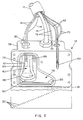
- a typical ink jet system of that type shown in Fig. 1, includes a main control unit 10 containing a remote ink supply reservoir 12 which is connected through an ink supply conduit 14 in a cable 15 to an ink jet printhead 16 and a pressure control unit 18 which is connected to the ink jet printhead 16 through an air conduit 19, also carried by the cable 15.
- the main control unit 10 includes a temperature control unit 22 for controlling the temperature of hot melt ink in various portions of the ink jet system.
- the printhead 16 is movably supported on a vertically disposed column 24 so as to be locked by a clamp 26 at any desired vertical position on the column.
- the printhead 16 is supported for pivotal motion in any vertical plane by a clampable universal joint 28 so that the printhead can be oriented to permit a linear array of ink jet orifices 30 therein, best seen in Fig. 2, to project ink horizontally, either in a horizontal line or in a vertical line, or downwardly.
- the line of orifices 30 is inclined at an angle to the direction of motion of objects which are to receive an image in order to increase the image resolution, i.e., decrease the adjacent line spacing in the image.
- the objects to be printed pass in a generally horizontal direction with respect to the orientation of the printhead 16 shown in Fig. 2, but the angular orientation of the printhead may be varied to increase or decrease the resolution.
- the printhead is disposed with the surface containing the printhead orifices 30 (shown in Fig. 2) in a horizontal orientation as shown in solid lines to cause the orifices to project a train of ink drops 31 downwardly onto the top surfaces 32 of a series of containers 34 which are conveyed in the horizontal direction by a conveyor 36, thus permitting appropriate information to be printed on the top surface of each of the containers.
- the printhead can be lowered on the column 24 and the universal joint 28 can be arranged to clamp the head 16 in an orientation corresponding to that shown in Fig. 2 but with the array of orifices 30 facing the near sides 37 of the containers 34, so as to cause information to be printed on the near side of each of the containers as they are conveyed past the printhead by the conveyor 36.
- the printing system of the invention may be arranged to print a series of labels 38 conveyed on a tape 40 in a vertical direction from one reel 42 to another reel 44 by adjusting the universal joint 28 t6 clamp the printhead in a vertical orientation, as shown in dotted outline in Fig. 1, so that the array of orifices 30 faces the labels 38 as they are conveyed in the vertical direction.
- the temperature control unit 22 is arranged to control the heater 50 so as to heat the block of hot melt ink 48 sufficiently to melt it and to maintain the ink in the supply reservoir 12 at a temperature just above its melting point so that it is sufficiently liquid that it can be transferred by a pump 53 through the supply conduit 14 to the printhead 16 as required.
- the ink temperature in the supply reservoir 12 is kept low enough so that no appreciable degradation will take place even though the ink is maintained continuously at that temperature for several days or weeks.
- the ink supply conduit 14 contains a thermostatically controlled heater 54 connected through a line 56 to the temperature control unit 22 so that the ink in the supply line is also maintained continuously in liquid condition, but at a temperature low enough that no appreciable degradation occurs.
- the ink jet printhead 16 includes a housing 58 containing a reservoir 60 in the form of an internal cavity 61 in the housing 58 which receives ink through the supply conduit 14 for replenishment when necessary.
- the supply conduit is connected to a filter 62 inserted in an internal passage 64 which communicates with the reservoir cavity 61.
- a heater element 66 received in a cylindrical recess 67 in the housing is connected through lines 68 in the cable 15 to the temperature control unit 22 and, to avoid overheating, a thermal fuse assembly 69 connected through corresponding lines 70 to the temperature control unit 22 is arranged to interrupt the supply of power to the heater 66 in the event of an overheat condition.
- the temperature of the ink in the printhead is maintained at a level determined by a temperature detecting thermistor 71 coupled through lines 72 to the temperature control unit 22.
- a low ink sensor 74 is positioned within the reservoir cavity 61, as shown in Fig. 2, at a location such that it will be covered with ink in any of the three mutually orthogonal printhead orientations described above until the volume of ink within the reservoir has been reduced to approximately one-half to one-third of its normal capacity.
- the low ink sensor 74 sends a signal through corresponding lines 76 to the pump 53 to transfer ink from the supply reservoir 12 to the printhead reservoir 60.
- the reservoir 60 To convey ink from the reservoir 60 to the array of orifices 30 in any of the three mutually orthogonal orientations of the printhead 16, the reservoir 60 includes a triangular passage 78 at one end of the cavity 61 leading to an outlet 80 disposed in spaced relation to a lower corner of the cavity 61.
- the passage 78 thus communicates with the corner of the reservoir cavity which is at the lowest level in any of the three printhead orientations described above with respect to Fig. 1.
- the passage 78 and the outlet 80 are at the lower right front portion of the reservoir 60.
- the outlet 80 leads to a duct 81 which conveys ink to adjacent pressure chambers of the conventional type (not shown) associated with each of the orifices 30 to cause ink drops to be ejected therefrom in response to ink ejection signals in the usual manner.
- the vent 82 enters the reservoir cavity 61 at a location diametrically opposite the triangular passage 78 and the outlet 80, i.e. in the upper left rear portion of the reservoir as seen in Fig. 2.
- the vent 82 is connected to the upper end of one leg 84 of a U-shaped tube 86 which, as best seen in Fig.
- leg 84 extends downwardly from the vent 82 along the rear wall of the reservoir cavity 61 and the lower portion 90 extends along the bottom wall of the reservoir cavity, i.e. below the normal minimum level of ink in the reservoir, while the other leg 88 extends upwardly along the rear wall adjacent to the leg 84 with the end of the leg 88 having an end 92 which is open to the atmosphere within the reservoir.
- the ink level is located below the open end 92 of the U-shaped tube in each of the three printhead orientations described above so that ink will not be caused to enter the open end 92 of the U-shaped tube during normal operation in any of those orientations.
- the maximum level of ink in the reservoir should be controlled so that it is below the open end 92 of the U-shaped tube.
- the printhead could be turned during handling or adjusting so that the open end of the U-shaped tube is below the level of ink or the reservoir could be shaken so that ink enters the open end of the U-shaped tube.
- the inner diameter of the passage in the U-shaped tube is made small enough, i.e. less than about 3 mm diameter, to cause the ink to form a plug, preventing passage of air. In this way, when operation of the printhead draws ink from the reservoir 60, the resulting pressure reduction in the airspace in the reservoir will draw the ink out of the open end 92 of the U-tube and back into the reservoir.
- the length of the U-shaped tube is made great enough so that, if tilting or inversion of the printhead causes the open end 92 of the U-shaped tube to be below the level of the ink in the reservoir, the bottom end 90 of the U-shaped tube which joins the legs 84 and 88 will at the same time be at least partially above the level of the ink in the reservoir. This produces a differential pressure which tends to prevent the ink from passing farther into the tube and avoids siphoning of the ink from the reservoir into the vent and the associated pressure or vacuum line.
- the reservoir 60 has a cavity 61 which is approximately 4.5 cm high, 2.5 cm wide and 2.5 cm deep and a triangular passage 78 which is about 2.5 cm long, 2 cm high at its large end, and 0.3 cm wide.
- the normal capacity of the reservoir is approximately 30 cc and the low ink sensor 74 is positioned to indicate a low ink condition with about 10-15 cc of ink remaining in the reservoir in each of the three orientations described above.
- the triangular passage 78 and the reservoir outlet 80 at the location described above the volume of ink remaining in the reservoir can be reduced to approximately 10% of its normal capacity, i.e. about 3 cc, before air could be drawn into the duct leading to the ink jet orifices 30.
Landscapes
- Engineering & Computer Science (AREA)
- Quality & Reliability (AREA)
- Ink Jet (AREA)
- Particle Formation And Scattering Control In Inkjet Printers (AREA)
Claims (15)
- Druckkopf (16) für einen Tintenstrahldrucker, mit:einer Matrix aus Öffnungen (30) zum Ausspritzen von Tintentropfen (31) in einer ausgewählten Richtung;Unterstützungsmitteln (24, 26, 28), durch die der Druckkopf in wenigstens zwei zueinander senkrechten Orientierungen unterstützt werden kann;einem Behälter für die Lieferung von Tinte an die Matrix aus Öffnungen im Druckkopf, der einen Tintenauslaß (80) besitzt, der sich in einem unteren Abschnitt des Behälters (60) befindet, wenn der Druckkopf in einer der zueinander senkrechten Orientierungen, in denen er unterstützt werden kann, orientiert ist;einem Belüftungsloch (82) zum Zuführen von Luft in den Behälter; undeinem Rohr (86) mit zwei im wesentlichen parallelen Abschnitten (84, 88), wovon einer (84) mit dem Belüftungsloch verbunden ist und der andere (88) ein Ende (92) besitzt, das sich über dem höchsten Pegel der Tinte im Behälter befindet, wenn sich der Druckkopf in irgendeiner seiner zueinander senkrechten Orientierungen befindet, wobei das Rohr (86) außerdem einen Mittelabschnitt (90) besitzt, der die im wesentlichen parallelen Abschnitte (84, 88) verbindet und sich in jeder der zueinander senkrechten Orientierungen des Druckkopfs unterhalb eines niedrigsten Pegels der Tinte im Behälter erstreckt.
- Druckkopf nach Anspruch 1, der eine Drucksteuerleitung (19) zum Anlegen eines gesteuerten Unterdrucks oder Überdrucks an das Belüftungsloch (82) umfaßt.
- Druckkopf nach Anspruch 1 oder 2, der ein Sensormittel (74) für wenig Tinte umfaßt, das im Behälter (60) an einer Stelle angeordnet ist, die so gewählt ist, daß sie einen Zustand mit wenig Tinte angibt, wenn der Behälter in irgendeiner der zueinander senkrechten Orientierungen orientiert ist.
- Druckkopf nach Anspruch 3, wobei das Sensormittel (74) für wenig Tinte im Behälter (60) an einer Stelle angeordnet ist, die so gewählt ist, daß sie einen Zustand mit wenig Tinte in jeder der zueinander senkrechten Orientierungen angibt, wenn sich der Behälter zwischen einem Drittel gefüllt und halb gefüllt befindet.
- Druckkopf nach einem vorhergehenden Anspruch, der eine Tintenzufuhrleitung (64) im Druckkopf zum Zuführen von Tinte in den Behälterhohlraum (61) und einen zylindrischen Filter (62), der in der Zufuhrleitung (64) aufgenommen ist, umfaßt.
- Druckkopf nach einem vorhergehenden Anspruch, der Heizmittel (66) zum Erhitzen von Tinte im Druckkopf (16) sowie Temperaturerfassungsmittel (71) zum Erfassen der Temperatur des Druckkopfs, die ermöglichen, die Heizmittel (66) in Übereinstimmung damit zu steuern, umfaßt.
- Druckkopf nach Anspruch 6, der Wärmeschmelzsicherungsmittel (69) umfaßt, die die Heizmittel (66) als Antwort auf einen Zustand überhöhter Temperatur im Druckkopf (16) außer Betrieb setzen.
- Druckkopf nach einem vorhergehenden Anspruch, wobei die Unterstützungsmittel (24, 26, 28) so beschaffen sind, daß sie den Druckkopf in einer von drei zueinander senkrechten Richtungen unterstützen.
- Druckkopf nach einem vorhergehenden Anspruch, wobei das Rohr (86) einen Innendurchmesser von nicht mehr als etwa 3 mm besitzt.
- Druckkopf nach einem vorhergehenden Anspruch, wobei die im wesentlichen parallelen Abschnitte (84, 88) des Rohrs (86) längs einer ersten Wand des Behälters (60) verlaufen und der Mittelabschnitt (90) längs einer zweiten Wand des Behälters zu einer Wand des Behälters gegenüber der ersten Wand verläuft.
- Druckkopf nach Anspruch 10, wobei der Mittelabschnitt (90) des Rohrs (86) so angeordnet ist, daß er sich über den höchsten Pegel der Tinte im Behälter (60) hinaus erstreckt, wenn der Druckkopf in bezug auf jede seiner zueinander senkrechten Orientierungen umdreht ist.
- Tintenstrahlsystem, das einen Tintenstrahl-Druckkopf nach einem vorhergehenden Anspruch sowie eine entfernte Tintenversorgung (12), die mit dem Druckkopfbehälter (60) verbunden ist, umfaßt.
- Tintenstrahlsystem nach Anspruch 12, wobei der Druckkopf wie in Anspruch 4 definiert beschaffen ist, ferner mit Mitteln, die die entfernte Tintenversorgung (12) dazu veranlassen, dem Druckkopfbehälter (60) Tinte zuzuführen, wenn durch die Sensormittel (74) ein Zustand mit wenig Tinte erfaßt wird.
- System nach Anspruch 12 oder 13, das Drucksteuermittel (118), die einen Überdruck oder einen Unterdruck erzeugen, und eine Vakuum- oder Druckleitung, die das Behälterbelüftungsloch mit den Drucksteuermitteln verbindet, umfassen.
- Strahlsystem nach den Ansprüchen 12, 13 oder 14, das Temperatursteuermittel (22) umfaßt, die die Temperatur der Tinte im Behälter auf einen gewünschten Pegel steuern.
Applications Claiming Priority (2)
| Application Number | Priority Date | Filing Date | Title |
|---|---|---|---|
| US08/641,109 US5920332A (en) | 1993-05-04 | 1996-04-29 | Ink barrier for fluid reservoir vacuum or pressure line |
| US641109 | 1996-04-29 |
Publications (3)
| Publication Number | Publication Date |
|---|---|
| EP0805034A2 EP0805034A2 (de) | 1997-11-05 |
| EP0805034A3 EP0805034A3 (de) | 1998-05-06 |
| EP0805034B1 true EP0805034B1 (de) | 2002-05-08 |
Family
ID=24570974
Family Applications (1)
| Application Number | Title | Priority Date | Filing Date |
|---|---|---|---|
| EP97300822A Expired - Lifetime EP0805034B1 (de) | 1996-04-29 | 1997-02-07 | Tintensperre für eine Unter- oder Überdruckleitung an einem Tintenbehälter |
Country Status (6)
| Country | Link |
|---|---|
| US (1) | US5920332A (de) |
| EP (1) | EP0805034B1 (de) |
| JP (1) | JPH1058710A (de) |
| DE (1) | DE69712402T2 (de) |
| ES (1) | ES2175272T3 (de) |
| GB (1) | GB2312649B (de) |
Families Citing this family (19)
| Publication number | Priority date | Publication date | Assignee | Title |
|---|---|---|---|---|
| JPH1134435A (ja) * | 1997-07-18 | 1999-02-09 | Brother Ind Ltd | インクジェットプリンタにおける動力伝達装置 |
| GB9910313D0 (en) | 1999-05-05 | 1999-06-30 | Cambridge Consultants | Fluid-pressure controlled ink pressure regulator |
| NL1014294C2 (nl) * | 2000-02-04 | 2001-08-07 | Ocu Technologies B V | Smeltinrichting en een inkjetprinter voorzien van een dergelijke smeltinrichting. |
| EP1780023B1 (de) | 2000-10-31 | 2008-08-13 | Zipher Limited | Druckvorrichtung |
| US7147313B2 (en) * | 2003-12-30 | 2006-12-12 | Xerox Corporation | Real time detection of ink stick jams in phasing printing systems |
| US7121658B2 (en) | 2004-01-07 | 2006-10-17 | Xerox Corporation | Print head reservoir having purge vents |
| DE602005014907D1 (de) | 2004-05-07 | 2009-07-30 | Miyakoshi Printing Mach | Tintenzuführvorrichtung für ein Tintenstrahlaufzeichnungsgerät |
| GB0428480D0 (en) * | 2004-12-30 | 2005-02-02 | Domino Printing Sciences Plc | Improvements in or relating to continuous inkjet printers |
| EP1775131B1 (de) * | 2005-10-17 | 2009-05-13 | Océ-Technologies B.V. | Tintenstrahlvorrichtung mit Belüftungsleitung |
| JP4892308B2 (ja) | 2005-10-17 | 2012-03-07 | オセ−テクノロジーズ ビーブイ | 通気導管付きインクジェット装置 |
| US7581827B2 (en) * | 2006-04-26 | 2009-09-01 | Xerox Corporation | System and method for melting solid ink sticks in a phase change ink printer |
| GB2447919B (en) * | 2007-03-27 | 2012-04-04 | Linx Printing Tech | Ink jet printing |
| US8052264B2 (en) * | 2008-03-26 | 2011-11-08 | Xerox Corporation | Melting device for increased production of melted ink in a solid ink printer |
| JP2010142995A (ja) * | 2008-12-17 | 2010-07-01 | Sii Printek Inc | 液体噴射ヘッドの回動装置、液体噴射記録装置及び液体噴射記録装置の液体充填方法 |
| US8024968B2 (en) * | 2009-02-02 | 2011-09-27 | Xerox Corporation | Apparatus and method for detecting ink in a reservoir |
| FR2956061B1 (fr) * | 2010-02-11 | 2012-12-21 | Markem Imaje | Imprimante a jet d'encre industrielle a communication numerique |
| US8562091B2 (en) * | 2010-03-09 | 2013-10-22 | Xerox Corporation | Apparatus and method for detecting ink in a reservoir using an overdriven thermistor and an electrical conductor extending from the thermistor |
| JP5645703B2 (ja) * | 2011-02-18 | 2014-12-24 | 東芝テック株式会社 | インクジェットヘッドおよびインクジェットヘッドの製造方法 |
| US11548290B2 (en) | 2020-08-28 | 2023-01-10 | Markem-Imaje Corporation | Systems and techniques for melting hot melt ink in industrial printing systems |
Family Cites Families (25)
| Publication number | Priority date | Publication date | Assignee | Title |
|---|---|---|---|---|
| US3123249A (en) * | 1964-03-03 | Venting arrangements for storage tanks | ||
| US2711252A (en) * | 1951-03-01 | 1955-06-21 | Tested Appliance Company | Dosing means for liquid systems |
| JPS555429B2 (de) * | 1973-09-26 | 1980-02-06 | ||
| US4648273A (en) | 1977-04-22 | 1987-03-10 | Ozols Karlis V | Force responsive device |
| US4370418A (en) * | 1981-07-24 | 1983-01-25 | University Of California | Liquid level control by subsurface draw off |
| US4471364A (en) * | 1982-09-28 | 1984-09-11 | Burroughs Corporation | Ramp style constant head ink jet cartridge |
| US4462307A (en) * | 1983-05-23 | 1984-07-31 | Pet Incorporated | Humpback oven-broiler |
| US4491433A (en) * | 1983-08-29 | 1985-01-01 | Centronics Data Computer Corp. | Venting and ink recycling device |
| JPS60101143U (ja) * | 1983-12-16 | 1985-07-10 | シャープ株式会社 | インクジエツトプリンタのインク供給装置 |
| US4709249A (en) * | 1984-06-21 | 1987-11-24 | Canon Kabushiki Kaisha | Ink jet recorder having ink container vent blocking means |
| US4539568A (en) * | 1984-10-15 | 1985-09-03 | Exxon Research And Engineering Co. | Hot melt ink jet having non-spill reservoir |
| US4961081A (en) * | 1987-07-08 | 1990-10-02 | Juki Corporation | Ink feeding mechanism for ink jet printers |
| US4791438A (en) * | 1987-10-28 | 1988-12-13 | Hewlett-Packard Company | Balanced capillary ink jet pen for ink jet printing systems |
| US4938037A (en) * | 1987-12-30 | 1990-07-03 | Carlisle Jr Billy M | Universal accumulator |
| US4931811A (en) * | 1989-01-31 | 1990-06-05 | Hewlett-Packard Company | Thermal ink jet pen having a feedtube with improved sizing and operational with a minimum of depriming |
| US4931812A (en) * | 1989-07-18 | 1990-06-05 | Hewlett-Packard Company | Flow control system for ink cartridges |
| EP0589540B1 (de) * | 1989-10-20 | 1997-10-01 | Canon Kabushiki Kaisha | Farbstrahlgerät und Kassette mit Tintenvorratsbehälter auf diesem Gerät aufstellbar |
| US5039999A (en) * | 1990-06-26 | 1991-08-13 | Hewlett-Packard Company | Accumulator and pressure control for ink-ket pens |
| JP3187870B2 (ja) * | 1990-08-17 | 2001-07-16 | キヤノン株式会社 | インクタンクおよび該インクタンクを用いるインクジェット記録装置 |
| DE69204191T2 (de) * | 1991-03-25 | 1996-01-25 | Tektronix Inc | Verfahren und Vorrichtung zum Zuführen einer Phasenaustausch-Tinte an einen Tintenstrahldrucker. |
| US5341160A (en) * | 1991-04-17 | 1994-08-23 | Hewlett-Packard Corporation | Valve for ink-jet pen |
| US5223860A (en) * | 1991-06-17 | 1993-06-29 | Tektronix, Inc. | Apparatus for supplying phase change ink to an ink jet printer |
| US5363130A (en) * | 1991-08-29 | 1994-11-08 | Hewlett-Packard Company | Method of valving and orientation sensitive valve including a liquid for controlling flow of gas into a container |
| JPH064183A (ja) * | 1992-06-22 | 1994-01-14 | Sharp Corp | 情報機器の電源制御装置 |
| US5489925A (en) * | 1993-05-04 | 1996-02-06 | Markem Corporation | Ink jet printing system |
-
1996
- 1996-04-29 US US08/641,109 patent/US5920332A/en not_active Expired - Lifetime
-
1997
- 1997-02-07 GB GB9702538A patent/GB2312649B/en not_active Expired - Lifetime
- 1997-02-07 EP EP97300822A patent/EP0805034B1/de not_active Expired - Lifetime
- 1997-02-07 ES ES97300822T patent/ES2175272T3/es not_active Expired - Lifetime
- 1997-02-07 DE DE69712402T patent/DE69712402T2/de not_active Expired - Lifetime
- 1997-04-15 JP JP9097319A patent/JPH1058710A/ja not_active Withdrawn
Also Published As
| Publication number | Publication date |
|---|---|
| JPH1058710A (ja) | 1998-03-03 |
| GB9702538D0 (en) | 1997-03-26 |
| GB2312649B (en) | 1999-08-11 |
| DE69712402D1 (de) | 2002-06-13 |
| DE69712402T2 (de) | 2002-08-29 |
| US5920332A (en) | 1999-07-06 |
| EP0805034A2 (de) | 1997-11-05 |
| EP0805034A3 (de) | 1998-05-06 |
| ES2175272T3 (es) | 2002-11-16 |
| GB2312649A (en) | 1997-11-05 |
Similar Documents
| Publication | Publication Date | Title |
|---|---|---|
| EP0805034B1 (de) | Tintensperre für eine Unter- oder Überdruckleitung an einem Tintenbehälter | |
| US4539568A (en) | Hot melt ink jet having non-spill reservoir | |
| US5187498A (en) | Ink supply container and system | |
| JP4036934B2 (ja) | インク配送システム | |
| CA1299914C (en) | Hot melt ink supply system | |
| JP4094709B2 (ja) | インクジェットプリンタ及びインクジェット・プリント方法 | |
| US6341853B1 (en) | Continuous refill of spring bag reservoir in an ink-jet swath printer/plotter | |
| JP3492441B2 (ja) | サーマル・インクジェット・プリントバーのバルブ・コネクタおよびインク処理システム | |
| US6457821B1 (en) | Filter carrier for protecting a filter from being blocked by air bubbles in an inkjet printhead | |
| EP0878308B1 (de) | Verfahren und Vorrichtung zur Vorhersage der Lebensdauer von einem Tintenstrahldruckkopf | |
| US6120139A (en) | Ink flow design to provide increased heat removal from an inkjet printhead and to provide for air accumulation | |
| US4658274A (en) | Melt ink jet apparatus with means and method for repriming | |
| JPS61135750A (ja) | ホットメルトインクを使用するための改良された貯留システムを有するインクジェット装置 | |
| EP3208094B1 (de) | Bestimmungssystem und druckflüssigkeitskartusche | |
| EP2305476B1 (de) | Entlüftung für einen Tintenstrahldruckkopf | |
| EP0875385B1 (de) | Ein einen getrennt einsetzbaren Filterträger verwendetes Tintenzuführsystem | |
| JP2005096208A (ja) | 画像形成装置のインク分配器 | |
| EP0178886B1 (de) | Tintenstrahlgerät und seine Arbeitsweise | |
| EP1095779B1 (de) | Nachfüllverfahren und -vorrichtung für Farbstoffbehälter | |
| EP0178884A2 (de) | Farbstrahlgerät und Verfahren zum Betrieb | |
| JP2000085146A (ja) | 液体吐出装置 | |
| JPH05246023A (ja) | インクジェットプリンタ | |
| JPH0531917A (ja) | インク貯蔵装置 | |
| MXPA98007283A (en) | Ink supply systems for ink jet printheads |
Legal Events
| Date | Code | Title | Description |
|---|---|---|---|
| PUAI | Public reference made under article 153(3) epc to a published international application that has entered the european phase |
Free format text: ORIGINAL CODE: 0009012 |
|
| AK | Designated contracting states |
Kind code of ref document: A2 Designated state(s): DE ES FR IT NL |
|
| PUAL | Search report despatched |
Free format text: ORIGINAL CODE: 0009013 |
|
| AK | Designated contracting states |
Kind code of ref document: A3 Designated state(s): DE ES FR IT NL |
|
| 17P | Request for examination filed |
Effective date: 19981022 |
|
| 17Q | First examination report despatched |
Effective date: 20000419 |
|
| GRAG | Despatch of communication of intention to grant |
Free format text: ORIGINAL CODE: EPIDOS AGRA |
|
| GRAG | Despatch of communication of intention to grant |
Free format text: ORIGINAL CODE: EPIDOS AGRA |
|
| GRAH | Despatch of communication of intention to grant a patent |
Free format text: ORIGINAL CODE: EPIDOS IGRA |
|
| GRAH | Despatch of communication of intention to grant a patent |
Free format text: ORIGINAL CODE: EPIDOS IGRA |
|
| GRAA | (expected) grant |
Free format text: ORIGINAL CODE: 0009210 |
|
| AK | Designated contracting states |
Kind code of ref document: B1 Designated state(s): DE ES FR IT NL |
|
| REF | Corresponds to: |
Ref document number: 69712402 Country of ref document: DE Date of ref document: 20020613 |
|
| ET | Fr: translation filed | ||
| REG | Reference to a national code |
Ref country code: ES Ref legal event code: FG2A Ref document number: 2175272 Country of ref document: ES Kind code of ref document: T3 |
|
| PGFP | Annual fee paid to national office [announced via postgrant information from national office to epo] |
Ref country code: NL Payment date: 20030121 Year of fee payment: 7 |
|
| PLBE | No opposition filed within time limit |
Free format text: ORIGINAL CODE: 0009261 |
|
| 26N | No opposition filed |
Effective date: 20030211 |
|
| PG25 | Lapsed in a contracting state [announced via postgrant information from national office to epo] |
Ref country code: NL Free format text: LAPSE BECAUSE OF NON-PAYMENT OF DUE FEES Effective date: 20040901 |
|
| NLV4 | Nl: lapsed or anulled due to non-payment of the annual fee |
Effective date: 20040901 |
|
| REG | Reference to a national code |
Ref country code: DE Ref legal event code: R082 Ref document number: 69712402 Country of ref document: DE Representative=s name: KADOR & PARTNER, DE |
|
| REG | Reference to a national code |
Ref country code: FR Ref legal event code: CD Owner name: MARKEM-IMAJE CORPORATION Effective date: 20120710 |
|
| REG | Reference to a national code |
Ref country code: ES Ref legal event code: PC2A Owner name: MARKEM-IMAJE CORPORATION Effective date: 20120802 |
|
| REG | Reference to a national code |
Ref country code: DE Ref legal event code: R082 Ref document number: 69712402 Country of ref document: DE Representative=s name: KADOR & PARTNER, DE Effective date: 20120627 Ref country code: DE Ref legal event code: R081 Ref document number: 69712402 Country of ref document: DE Owner name: MARKEM-IMAJE CORP., US Free format text: FORMER OWNER: MARKEM CORP., KEENE, US Effective date: 20120627 Ref country code: DE Ref legal event code: R081 Ref document number: 69712402 Country of ref document: DE Owner name: MARKEM-IMAJE CORP., KEENE, US Free format text: FORMER OWNER: MARKEM CORP., KEENE, N.H., US Effective date: 20120627 |
|
| REG | Reference to a national code |
Ref country code: FR Ref legal event code: PLFP Year of fee payment: 19 |
|
| PGFP | Annual fee paid to national office [announced via postgrant information from national office to epo] |
Ref country code: IT Payment date: 20150225 Year of fee payment: 19 Ref country code: ES Payment date: 20150226 Year of fee payment: 19 |
|
| REG | Reference to a national code |
Ref country code: FR Ref legal event code: PLFP Year of fee payment: 20 |
|
| PGFP | Annual fee paid to national office [announced via postgrant information from national office to epo] |
Ref country code: DE Payment date: 20160226 Year of fee payment: 20 |
|
| PGFP | Annual fee paid to national office [announced via postgrant information from national office to epo] |
Ref country code: FR Payment date: 20160217 Year of fee payment: 20 |
|
| PG25 | Lapsed in a contracting state [announced via postgrant information from national office to epo] |
Ref country code: IT Free format text: LAPSE BECAUSE OF NON-PAYMENT OF DUE FEES Effective date: 20160207 |
|
| REG | Reference to a national code |
Ref country code: DE Ref legal event code: R071 Ref document number: 69712402 Country of ref document: DE |
|
| PG25 | Lapsed in a contracting state [announced via postgrant information from national office to epo] |
Ref country code: ES Free format text: LAPSE BECAUSE OF NON-PAYMENT OF DUE FEES Effective date: 20160208 |