EP2305476B1 - Entlüftung für einen Tintenstrahldruckkopf - Google Patents
Entlüftung für einen Tintenstrahldruckkopf Download PDFInfo
- Publication number
- EP2305476B1 EP2305476B1 EP10179093A EP10179093A EP2305476B1 EP 2305476 B1 EP2305476 B1 EP 2305476B1 EP 10179093 A EP10179093 A EP 10179093A EP 10179093 A EP10179093 A EP 10179093A EP 2305476 B1 EP2305476 B1 EP 2305476B1
- Authority
- EP
- European Patent Office
- Prior art keywords
- ink
- reservoir
- opening
- printhead
- lower opening
- Prior art date
- Legal status (The legal status is an assumption and is not a legal conclusion. Google has not performed a legal analysis and makes no representation as to the accuracy of the status listed.)
- Not-in-force
Links
- 239000000523 sample Substances 0.000 claims description 20
- 238000000034 method Methods 0.000 claims description 4
- 238000013022 venting Methods 0.000 claims description 3
- 230000005499 meniscus Effects 0.000 claims description 2
- 238000010926 purge Methods 0.000 claims 1
- 239000000976 ink Substances 0.000 description 171
- 239000012071 phase Substances 0.000 description 21
- 230000008859 change Effects 0.000 description 17
- 239000007788 liquid Substances 0.000 description 11
- 239000007791 liquid phase Substances 0.000 description 7
- 230000005855 radiation Effects 0.000 description 6
- 239000007787 solid Substances 0.000 description 5
- 239000000758 substrate Substances 0.000 description 5
- 239000000155 melt Substances 0.000 description 4
- 238000007639 printing Methods 0.000 description 4
- 230000004044 response Effects 0.000 description 4
- 238000001879 gelation Methods 0.000 description 3
- 230000008878 coupling Effects 0.000 description 2
- 238000010168 coupling process Methods 0.000 description 2
- 238000005859 coupling reaction Methods 0.000 description 2
- 238000003384 imaging method Methods 0.000 description 2
- 238000002844 melting Methods 0.000 description 2
- 230000008018 melting Effects 0.000 description 2
- 239000007790 solid phase Substances 0.000 description 2
- 239000003086 colorant Substances 0.000 description 1
- 238000001816 cooling Methods 0.000 description 1
- 230000001419 dependent effect Effects 0.000 description 1
- 238000010586 diagram Methods 0.000 description 1
- 239000000839 emulsion Substances 0.000 description 1
- 239000007789 gas Substances 0.000 description 1
- 239000012535 impurity Substances 0.000 description 1
- 238000007641 inkjet printing Methods 0.000 description 1
- 239000000203 mixture Substances 0.000 description 1
- 239000008188 pellet Substances 0.000 description 1
- 230000002093 peripheral effect Effects 0.000 description 1
- 230000008569 process Effects 0.000 description 1
- 230000006903 response to temperature Effects 0.000 description 1
Images


Classifications
-
- B—PERFORMING OPERATIONS; TRANSPORTING
- B41—PRINTING; LINING MACHINES; TYPEWRITERS; STAMPS
- B41J—TYPEWRITERS; SELECTIVE PRINTING MECHANISMS, i.e. MECHANISMS PRINTING OTHERWISE THAN FROM A FORME; CORRECTION OF TYPOGRAPHICAL ERRORS
- B41J2/00—Typewriters or selective printing mechanisms characterised by the printing or marking process for which they are designed
- B41J2/005—Typewriters or selective printing mechanisms characterised by the printing or marking process for which they are designed characterised by bringing liquid or particles selectively into contact with a printing material
- B41J2/01—Ink jet
- B41J2/17—Ink jet characterised by ink handling
- B41J2/19—Ink jet characterised by ink handling for removing air bubbles
-
- B—PERFORMING OPERATIONS; TRANSPORTING
- B41—PRINTING; LINING MACHINES; TYPEWRITERS; STAMPS
- B41J—TYPEWRITERS; SELECTIVE PRINTING MECHANISMS, i.e. MECHANISMS PRINTING OTHERWISE THAN FROM A FORME; CORRECTION OF TYPOGRAPHICAL ERRORS
- B41J2/00—Typewriters or selective printing mechanisms characterised by the printing or marking process for which they are designed
- B41J2/005—Typewriters or selective printing mechanisms characterised by the printing or marking process for which they are designed characterised by bringing liquid or particles selectively into contact with a printing material
- B41J2/01—Ink jet
- B41J2/135—Nozzles
- B41J2/14—Structure thereof only for on-demand ink jet heads
- B41J2/14016—Structure of bubble jet print heads
- B41J2/14032—Structure of the pressure chamber
- B41J2/1404—Geometrical characteristics
-
- B—PERFORMING OPERATIONS; TRANSPORTING
- B41—PRINTING; LINING MACHINES; TYPEWRITERS; STAMPS
- B41J—TYPEWRITERS; SELECTIVE PRINTING MECHANISMS, i.e. MECHANISMS PRINTING OTHERWISE THAN FROM A FORME; CORRECTION OF TYPOGRAPHICAL ERRORS
- B41J2/00—Typewriters or selective printing mechanisms characterised by the printing or marking process for which they are designed
- B41J2/005—Typewriters or selective printing mechanisms characterised by the printing or marking process for which they are designed characterised by bringing liquid or particles selectively into contact with a printing material
- B41J2/01—Ink jet
- B41J2/135—Nozzles
- B41J2/16—Production of nozzles
- B41J2/1621—Manufacturing processes
- B41J2/164—Manufacturing processes thin film formation
- B41J2/1643—Manufacturing processes thin film formation thin film formation by plating
-
- B—PERFORMING OPERATIONS; TRANSPORTING
- B41—PRINTING; LINING MACHINES; TYPEWRITERS; STAMPS
- B41J—TYPEWRITERS; SELECTIVE PRINTING MECHANISMS, i.e. MECHANISMS PRINTING OTHERWISE THAN FROM A FORME; CORRECTION OF TYPOGRAPHICAL ERRORS
- B41J2/00—Typewriters or selective printing mechanisms characterised by the printing or marking process for which they are designed
- B41J2/005—Typewriters or selective printing mechanisms characterised by the printing or marking process for which they are designed characterised by bringing liquid or particles selectively into contact with a printing material
- B41J2/01—Ink jet
- B41J2/17—Ink jet characterised by ink handling
- B41J2/175—Ink supply systems ; Circuit parts therefor
- B41J2/17503—Ink cartridges
- B41J2/17513—Inner structure
-
- B—PERFORMING OPERATIONS; TRANSPORTING
- B41—PRINTING; LINING MACHINES; TYPEWRITERS; STAMPS
- B41J—TYPEWRITERS; SELECTIVE PRINTING MECHANISMS, i.e. MECHANISMS PRINTING OTHERWISE THAN FROM A FORME; CORRECTION OF TYPOGRAPHICAL ERRORS
- B41J2/00—Typewriters or selective printing mechanisms characterised by the printing or marking process for which they are designed
- B41J2/005—Typewriters or selective printing mechanisms characterised by the printing or marking process for which they are designed characterised by bringing liquid or particles selectively into contact with a printing material
- B41J2/01—Ink jet
- B41J2/17—Ink jet characterised by ink handling
- B41J2/175—Ink supply systems ; Circuit parts therefor
- B41J2/17503—Ink cartridges
- B41J2/17556—Means for regulating the pressure in the cartridge
-
- B—PERFORMING OPERATIONS; TRANSPORTING
- B41—PRINTING; LINING MACHINES; TYPEWRITERS; STAMPS
- B41J—TYPEWRITERS; SELECTIVE PRINTING MECHANISMS, i.e. MECHANISMS PRINTING OTHERWISE THAN FROM A FORME; CORRECTION OF TYPOGRAPHICAL ERRORS
- B41J2/00—Typewriters or selective printing mechanisms characterised by the printing or marking process for which they are designed
- B41J2/005—Typewriters or selective printing mechanisms characterised by the printing or marking process for which they are designed characterised by bringing liquid or particles selectively into contact with a printing material
- B41J2/01—Ink jet
- B41J2/17—Ink jet characterised by ink handling
- B41J2/175—Ink supply systems ; Circuit parts therefor
- B41J2/17593—Supplying ink in a solid state
Definitions
- the device and method described below relate to inkjet imaging devices and, more particularly, to printheads in inkjet imaging devices.
- Inkjet printers form a printed image by ejecting or "jetting" small droplets of liquid ink onto an image receiving surface, such as an intermediate transfer surface or a media substrate.
- the benefits of inkjet printing include low printing noise, low cost per printed page, and the ability to print "full color” images.
- Inkjet printers include, among other components, a printhead and a printhead controller. The printhead controller selectively sends ejection signals to the printhead that cause ejectors within the printhead to eject droplets of liquid ink upon an image receiving surface to form at least a portion of a printed image.
- inkjet printheads include a plurality of ink ejectors and at least one reservoir for storing a quantity of ink.
- Monochromatic inkjet printheads may include a single reservoir for containing a single color of ink.
- Full color inkjet printheads may include a plurality of reservoirs, with each reservoir configured to contain a different color of ink.
- a full color inkjet printhead may include four reservoirs with each reservoir containing one of the four colors of ink typically used to generate full color images; namely, cyan, magenta, yellow, and black.
- the ink ejectors eject very small droplets of the ink onto an image receiving surface.
- a group of one hundred to six hundred individual ink ejectors are coupled by a manifold to a single ink reservoir.
- a monochromatic printhead may include a single group of ink ejectors fluidly coupled to the single reservoir, while a full color printhead may include a separate group of ink ejectors for each of the reservoirs.
- a full color printhead having four reservoirs may have four groups of ink ejectors, each of which is fluidly coupled to a different ink reservoir.
- An ink reservoir of an inkjet printhead may include a reservoir vent that permits air to enter and exit the reservoir.
- the vent allows air to be expelled from the reservoir in response to the reservoir being filled with ink. Additionally, the vent enables air to enter the reservoir as ink is ejected by the ink ejectors. Therefore, ink reservoir vents operate to equalize air pressure within the ink reservoir.
- reservoir vents typically include a vent opening positioned in a region of the ink reservoir located above a maximum ink level.
- a printer may be moved or repositioned. These movements may allow ink within the reservoir to migrate to the vent opening and be spilled from the reservoir. The spilled ink, as a consequence, is lost for printing and may contact parts of the printer not designed for ink contact. Therefore, more inkjet reservoir venting solutions are desirable.
- US 2002/0063759 A1 discloses an ink tank with a member that permit air to pass without permitting leakage of ink.
- FIG. 1 is a cross sectional view of an inkjet printhead having a vent as described herein.
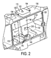
- FIG. 2 is a perspective cross sectional view of an ink reservoir in an inkjet printhead having a vent as described herein.
- FIG. 3 is a cross sectional view of the inkjet printhead of FIG. 1 having a vent as described herein.
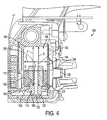
- FIG. 4 is a cross sectional view of the inkjet printhead and vent of FIG. 1 shown in an inverted position.
- FIG. 5 is a block diagram depicting a side view of a phase change ink printing system having the printhead of FIG. 1 .
- the vent described herein is suitable for use with a printer.
- printer refers, for example, to reproduction devices in general, such as printers, facsimile machines, copiers, and related multi-function products. While the specification focuses on an inkjet printer, the vent described herein may be used with any printer that contains a supply of ink. Furthermore, the vent described herein may be used with printers that form printed images with either aqueous ink or phase change ink.
- a printhead 100 of an inkjet printer forms a printed image by ejecting droplets of liquid ink onto an image receiving surface.
- liquid ink includes, but is not limited to, aqueous inks, liquid ink emulsions, pigmented inks, and phase change inks in a liquid phase.
- the printhead 100 includes, among other components, a reservoir 104, an ink inlet 108, numerous ink ejectors 112, a vent opening 116, and a vent member provided herein as a vent tube 120.
- the reservoir 104 contains a supply of ink 124 for ejection onto the image receiving surface by the ink ejectors 112, which may be provided as thermal ink ejectors and/or piezoelectric ink ejectors, as is known in the art.
- the reservoir 104 may be filled with additional ink via the ink inlet 108, which is fluidly coupled to a main reservoir 262 ( FIG. 5 ).
- the vent tube 120 which extends into the reservoir 104 through the vent opening 116, permits air to enter and exit the reservoir 104.
- the ink reservoir 104 may include a first pair of opposed sidewalls 128, 130, a second pair of opposed sidewalls 132 (only one of which is shown in FIG. 2 ), an upper wall 136, and a lower wall 140 that define a volume for containing the supply of ink 124.
- a reservoir height may be defined by a distance between the upper wall 136 and the lower wall 140.
- a reservoir width may be defined by a distance between sidewall 128 and sidewall 130.
- the reservoir 104 may have a cross section of any shape suitable for containing the supply of ink 124, including, but not limited to, square, circular, and elliptical. Therefore, in some embodiments the upper wall 136, lower wall 140, and sidewalls 128, 130, 132 may not be sharply delineated. Additionally, as shown in FIG. 1 , the ink reservoir 104 may define a volumetric center 142. A plane extending through the volumetric center 142 divides the reservoir 104 into two regions having approximately the same volume.
- the ink inlet 108 is formed in one or more of the reservoir walls. As mentioned above, the ink inlet 108 is fluidly coupled to the main reservoir 262. When the supply of ink 124 in the reservoir 104 has dropped to or below a minimum value, the reservoir 104 receives ink from the main reservoir 262 through the ink inlet 108 until the reservoir 104 has been filled to a predetermined maximum ink level, represented by Line C of FIG. 1 .
- the ink inlet 108 may include a filter or screen 144 to prevent impurities from entering the ink reservoir 104.
- the reservoir walls 128, 130, 132, 136, 140 and the upper surface of the supply of ink 124 define an air space 148 above the supply of ink 124.
- the reservoir 104 may be filled to a predetermined maximum ink level.
- a volume of air is present above the upper surface of the supply of ink 124. This volume of air is referred to as the air space 148.
- the lower boundary of the air space 148 is defined by the upper surface of the supply of ink 124, and the upper boundary of the air space 148 is defined by the upper wall 136.
- the upper boundary of the air space 148 may be defined by any of the reservoir walls 128, 130, 132, 136, 140. For instance, if the printhead 100 is positioned upon a sloped surface the upper boundary of the air space 148 may be defined partially by sidewall 128 and partially by the upper wall 136. Additionally, if the printhead is oriented in an extreme position, the upper boundary of the air space 148 may be defined entirely, for instance, by sidewall 128 or even lower wall 140. Therefore, the portion of the reservoir 104 defining the upper boundary of the air space 148 depends upon the orientation of the printhead 100.
- the vent opening 116 in the ink reservoir 104 is an aperture formed in one or more of the reservoir walls 128, 130, 132, 136, 140 that permits a portion of the vent tube 120 to extend into the ink reservoir 104. As shown in FIGS. 1 and 3 , the vent opening 116 has been formed in the upper wall 136; however, the opening 116 may be formed in any one or more of the reservoir walls 128, 130, 132, 136, 140.
- the vent opening 116 engages the vent tube 120 to form an air and liquid impervious seal, which prevents ink from seeping out of the reservoir 104 through the junction between the vent tube 120 and the vent opening 116.
- the vent opening 116 may define an approximately circular opening to engage a vent tube 120 having an approximately circular periphery.
- the vent opening 116 may define a rectangular, square, or elliptical opening to engage a vent tube 120 having an aptly shaped periphery.
- the vent tube 120 permits air to enter and exit the reservoir 104, but prevents ink from flowing out of the reservoir 104. As shown in FIGS. 1 and 3 , the vent tube 120 extends from the vent opening 116 into the reservoir 104.
- the vent tube 120 includes an upper opening 152, a lower opening 156, and a channel 160, which fluidly couples the upper opening 152 to the lower opening 156.
- the channel 160 as illustrated in FIGS. 1 and 3 , is approximately cylindrical, the channel 160 may be any shape including a non-uniform shape having a nonlinear cross section.
- the upper opening 152 is an aperture at the top of the channel 160 that, as shown in FIGS. 1-3 , is exposed to the atmosphere. In some embodiments, the upper opening 152 may be remotely located by fluidly coupling a channel extension (not illustrated) or other printer accessory to the upper opening 152.
- the lower opening 156 is an aperture at the bottom of the channel 160. As shown in FIG. 1 , the lower opening 156 is positioned approximately at the volumetric center 142 of the ink reservoir 104, within the air space 148. In particular, the lower opening 156 may be positioned approximately one half of the reservoir height A from the lower wall 140 and one half of the reservoir width B from a sidewall 128, 130. In this position, the lower opening 156 remains in the air space 148 regardless of the orientation of the printhead 100.
- the position of the lower opening 156 prevents the supply of ink 124 from exiting the reservoir 104 through the channel 160.
- the maximum ink level is limited to an amount that enables the lower opening 156 to remain in the air space 148 regardless of the position of the printhead 100.
- the maximum ink level is slightly less than half of the volume of the reservoir 104, such that when the lower opening 156 is positioned at or near the volumetric center 142 it does not contact the supply of ink 124 regardless of the orientation of the printhead 100.
- lines C, D, E, and F of FIG. 1 identify the maximum ink level when the printhead 100 is oriented in various extreme positions.
- line C identifies the upper surface of the supply of ink 124 when the printhead 100 is in an upright position.
- Lines E and F identify the upper surface of the supply of ink 124 when the printhead 100 is laterally oriented.
- Line D identifies the upper surface of the supply of ink 124 when the printhead 100 is inverted, as shown in FIG. 4 .
- the supply of ink 124 may surround a portion of the vent tube 120; however, the upper surface of the supply of ink 124 remains below the lower opening 156 to prevent the supply of ink 124 from flowing through the channel 160.
- a buffer of air is present between the upper surface of the supply of ink 124 and the lower opening 156 to prevent the supply of ink 124 from entering the channel 160 and exiting the reservoir 104 through the vent tube 120.
- the lower opening 156 remains in the air space 148 in response to the printhead 100 being rotated about any axis of rotation. For instance, the lower opening 156 remains in the air space 148 as the printhead 100 is transitioned between the upright position of FIG. 1 and the inverted position of FIG. 4 .
- the vent tube 120 prevents ink from impeding an airflow through the channel 160 if the supply of ink 124 contacts the lower opening 156.
- the lower opening 156 remains in the air space 148; however, if the printhead 100 is subject to a severe jostling or extreme vibrations, the supply of ink 124 may briefly contact the lower opening 156.
- the lower opening 156 has a width or diameter in excess of a predetermined value.
- the predetermined value is at least partially determined by the surface tension of the ink. In particular, ink having a high surface tension results in a greater predetermined value as compared to an ink having a low surface tension.
- the vent tube 120 may include an upper extension 168, which extends from the vent opening 116 above the upper wall 136.
- the upper extension 168 may be coupled to a second tube (not illustrated) in order to locate the upper opening 152 remotely.
- the vent tube 120 may be incorporated within a sensor probe 172 removably connected to the vent opening 116.
- a sensor probe 172 having a vent tube 120 may position at least one sensor 176 within the volume of the reservoir 104.
- the sensor 176 may generate one or more signals indicative of the level of ink in the reservoir 104.
- the sensor probe 172 may position a sensor 176 to detect when the supply of ink 124 has reached a minimum or a maximum level.
- the sensor probe 172 may position a sensor 176 to detect the level of ink in the reservoir 104 over a continuous range.
- the sensor probe 172 may position a sensor 176 above the maximum level of ink to detect a temperature of the air space 148.
- the sensor probe 172 may also position a component of a multipart sensor, referred to as a sensing element, within the reservoir 104.
- the sensing element or elements may generate one or more signals indicative of the level of ink in the reservoir 104. For instance, a pair of sensing elements may be positioned within the reservoir 104 to generate a "full" signal when one or more sensing elements are in contact with the supply of ink 124 and to generate a "low” signal when one or more of the sensing elements are not in contact with the supply of ink 124. Additionally, the sensing element or elements may be positioned to detect the level of ink in the reservoir 104 over a continuous range.
- the sensor probe 172 includes at least one channel 180 (as shown in FIG. 3 ), an upper portion 184, a lower portion 188, and in some embodiments a cross channel 192 (as shown in FIG. 3 ).
- the at least one channel 180 enables the one or more sensing elements or sensors 176 to be positioned within the sensor probe 172.
- the channels 180 may originate in the upper portion 184 and terminate at or near a peripheral portion of the sensor probe 172.
- the channels 180 permit wires or leads 194 electrically coupled to a sensing element or a sensor 176 to extend from the ink reservoir 104 without contacting the supply of ink 124 or the air space 148.
- the channels 180 are isolated from channel 160 and the cross channel 192.
- the cross channel 192 is formed at the interface of the upper portion 184 and the lower portion 188 of the sensor probe 172.
- the cross channel 192 fluidly couples the lower opening 156 to the air space 148.
- the cross channel 192 is approximately perpendicular to channel 160.
- Embodiments of the sensor probe 172 having a cross channel 192 include effective lower openings 196, 200 at the ends of the cross channel 192 near the periphery of the vent tube 120. One or more of these effective lower openings 196, 200 and the lower opening 156 remain in the air space 148 regardless of the orientation of the printhead 100.
- the printhead 100 may be oriented to position effective lower opening 196 in contact with the supply of ink 124, effective lower opening 200 and lower opening 156 remain above the upper surface of the supply of ink 124 in the air space 148, to prevent ink from spilling from the reservoir 104 through the channel 160.
- the vent tube 120 may fluidly couple the reservoir 104 to the atmosphere. In other embodiments, the vent tube 120 may fluidly couple the reservoir 104 to an air pressure device (not illustrated) that selectively couples the air space 148 to one of the atmosphere, a source of air pressure greater than atmospheric pressure, and a source of air pressure lower than atmospheric pressure.
- the printhead 100 may include a coupling tube (not illustrated) for connecting the air pressure device to the upper opening 152.
- the air pressure device may maintain either a positive or negative pressure within the reservoir 104. Even when the air pressure device is coupled to the reservoir 104, the vent tube 120 permits air pressure levels within the reservoir 104 to fluctuate as ink is filled and ejected from the reservoir 104.
- a phase change ink printer 250 may include an ink loader 254, a melting device 258, a main reservoir 262, and a media path 270.
- the printer 250 ejects phase change ink upon an image receiving surface or a substrate 266 transported on a media path 270.
- phase change ink encompasses inks that are installed in the printer 250 in a first phase or state and that are ejected upon a substrate 266 after changing to a second phase or state.
- the change to a second phase or state may include, but is not limited to, changing from a solid to a liquid, changing from a gel to a liquid, and changing from a high viscosity to a low viscosity.
- solid phase change ink refers to inks that remain in a solid phase at an ambient temperature and that melt into a liquid phase when heated above a melt temperature.
- the ambient temperature is the temperature of the air surrounding the printer 250. Therefore, the ambient temperature may be a room temperature when the printer 250 is positioned in a defined space; however, the ambient temperature may be above a room temperature when portions of the printer 250, such as the media path 270, are enclosed by, for example, a cover.
- melt temperatures is approximately seventy to one hundred forty degrees Celsius; however, the melt temperature of some types of solid phase change inks may be above or below the exemplary temperature range.
- gel based phase change ink or gel ink refers to inks that remain in a gelatinous phase or state at an ambient temperature and that melt into a liquid phase when heated above a gelation or melt temperature.
- An exemplary range of gelation temperatures is approximately thirty to fifty degrees Celsius; however, the gelation temperature of some types of gel-based phase change inks may be above or below the exemplary temperature range.
- Some inks may be cured during the printing process.
- Radiation curable ink becomes cured after being exposed to a source of radiation. Suitable radiation includes, but is not limited to, infrared, visible, and ultraviolet.
- ultraviolet-curable gel based phase change ink referred to herein as UV gel ink, becomes cured after being exposed to ultraviolet radiation.
- the ink loader 254 contains a quantity of phase change ink in the solid or gelatinous phase. Phase change ink is supplied to the ink loader 254 as solid ink pellets, solid ink sticks, or a quantity of gel-based ink, among other forms.
- the ink loader 254 moves the phase change ink toward the melting device 258, which melts a portion of the ink into the liquid phase.
- the liquid ink is delivered to the main reservoir 262, which is thermally coupled to a heater 274 configured to heat the main reservoir 262 to a temperature that maintains the ink in the liquid phase. Liquid ink from the main reservoir 262 is delivered to the printhead 100.
- the ink is delivered to the ink reservoir 104 through ink inlet 108, as shown in FIGS. 1 , 3 , and 4 .
- the printhead 100 may include a heater 278 for maintaining the ink contained by the ink reservoir 104 in the liquid phase.
- the main reservoir 262 and the ink reservoir 104 may be configured to remain coupled to the printer 250 during normal usage and servicing of the printer 250. Specifically, when the ink level in the ink reservoir 104 falls below a predetermined level, the printer 250 refills the ink reservoir 104 with liquid ink from the main reservoir 262. Similarly, when the ink level in the main reservoir 262 falls below a predetermined level, the printer 250 is configured to fill the main reservoir 262 with additional ink from the ink loader 254. Accordingly, in one embodiment, neither the main reservoir 262 nor the ink reservoir 104 are disposable units configured to be replaced when the printer 250 exhausts an ink supply.
- the printer 250 may be configured to form printed images with UV gel ink.
- UV gel ink remains in a gelatinous state or phase having a comparatively high viscosity at the ambient temperature. When heated to or above the melt temperature, however, the viscosity of UV gel ink is reduced, and the ink enters a liquid phase that is suitable for ejection by the printhead 112.
- a printer 250 configured to eject UV gel ink may include a leveling device 282 and a source of ultraviolet radiation 286.
- the leveling device 282 is configured to blend droplets of UV gel ink, and other types of ink, into a substantially continuous area.
- the leveling device 282 may be a thermal reflow device configured to heat the ink ejected upon the substrate 114 to a temperature, which blends together ink droplets of the ink.
- the UV gel ink ejected upon the substrate 266 may be exposed to the source of ultraviolet radiation 286, which is configured to cure the ink.
- the vent tube 120 when coupled to a phase change ink printer 250 enables air, or other gases, to enter and exit the air space 148 in response to temperature changes of the ink 124.
- the vent tube 120 permits air to escape the air space 148 as ink in the reservoir 104 is heated.
- the vent tube 120 permits air to enter the air space 148 in response to the ink in the reservoir 104 cooling.
Landscapes
- Engineering & Computer Science (AREA)
- Manufacturing & Machinery (AREA)
- Physics & Mathematics (AREA)
- Geometry (AREA)
- Ink Jet (AREA)
- Particle Formation And Scattering Control In Inkjet Printers (AREA)
Claims (11)
- Tintenstrahl-Druckkopf (100) zum selektiven Ausstoßen von Tinte auf eine Bildaufnahmefläche, wobei der Tintenstrahl-Druckkopf (100) umfasst:einen Vorratsbehälter (104) zum Aufnehmen eines Tintenvorrats, wobei der Vorratsbehälter (104) durch eine Vielzahl von Vorratsbehälter-Wänden (128, 130, 132, 136, 140) gebildet wird und der Vorratsbehälter (104) bis zu einem vorgegebenen maximalen Tintenpegel (C, D, E, F) gefüllt ist, so dass die Vorratsbehälter-Wände (128, 130, 132, 136, 140) und die obere Fläche des Tintenvorrates einen Luftraum (148) bilden,einen Tinteneinlass (108), der in einer der Vielzahl von Vorratsbehälter-Wänden (128, 130, 132, 136, 140) ausgebildet ist;eine Belüftungs-Öffnung (116), die in einer der Vielzahl von Vorratsbehälter-Wänden (128, 130, 132, 136, 140) ausgebildet ist; undein Belüftungselement (120), das sich von der Belüftungsöffnung (116) aus erstreckt, wobei das Belüftungselement (120) eine obere Öffnung (152), die in einem Luftraum außerhalb des Vorratsbehälters angeordnet ist, eine untere Öffnung (156), die in dem Luftraum (148) über dem Tintenvorrat angeordnet ist, sowie einen Kanal (160) aufweist, der zum Fluidverbinden der oberen Öffnung (152) mit der unteren Öffnung (156) konfiguriert ist,wobei die untere Öffnung (156) in dem Vorratsbehälter (104) annähernd am räumlichen Mittelpunkt (142) des Vorratsbehälters (104) angeordnet ist, undder maximale Tintenpegel (C, D, E, F) geringfügig kleiner ist als die Hälfte des Volumens des Vorratsbehälters (140), so dass ein Verbleiben der unteren Öffnung (156) in dem Luftraum (148) über dem Tintenvorrat unabhängig von einer Ausrichtung des Vorratsbehälters (104) ermöglicht ist.
- Tintenstrahl-Druckkopf (100) nach Anspruch 1, wobei das Belüftungselement (120) eine Röhre ist, die abnehmbar mit der Belüftungsöffnung (116) verbunden ist.
- Tintenstrahl-Druckkopf (100) nach Anspruch 1, wobei sich das Belüftungselement (120) in einer Sensor-Sonde (172) befindet, die Sensor-Sonde (172) abnehmbar mit der Belüftungsöffnung (116) verbunden ist und die Sensor-Sonde (172) wenigstens einen Kanal (120) zum Positionieren wenigstens eines Erfassungselementes (176) in dem Vorratsbehälter (104) aufweist.
- Tintenstrahl-Druckkopf (100) nach Anspruch 3, wobei die Sensor-Sonde (172) des Weiteren umfasst:ein erstes Tinten-Erfassungselement (176), das sich durch einen ersten Kanal (180) hindurch erstreckt; undein zweites Tinten-Erfassungselement (176), das sich durch einen zweiten Kanal (180) hindurch erstreckt, wobei das erste und das zweite Tinten-Erfassungselement (172) so konfiguriert sind, dass sie wenigstens ein Signal erzeugen, das einen von dem Vorratsbehälter aufgenommenen Tintenpegel anzeigt.
- Tintenstrahl-Druckkopf (100) nach Anspruch 3, wobei die Sensor-Sonde (172) des Weiteren umfasst:einen ersten Sensor-Sondenabschnitt (184);einen zweiten Sensor-Sondenabschnitt (188); undeinen Querkanal (192), der an einer Grenzfläche des ersten Sensor-Sondenabschnitts (184) und des zweiten Sensor-Sondenabschnitts (188) ausgebildet ist, wobei der Querkanal (192) zum Fluidverbinden der unteren Öffnung (156) mit dem Luftraum (148) über dem Tintenvorrat konfiguriert ist.
- Tintenstrahl-Druckkopf (100) nach Anspruch 1, wobei die untere Öffnung (156) eine Breite hat, die so eingerichtet ist, dass ein Ausbilden eines Tinten-Meniskus über die untere Öffnung (156) verhindert wird, und die Breite der unteren Öffnung (156) wenigstens teilweise durch eine Oberflächenspannung des Tintevorrats bestimmt wird.
- Tintenstrahl-Druckkopf (100) nach Anspruch 1, der des Weiteren umfasst:eine Luftüberdruckquelle, die in Fluidverbindung mit der oberen Öffnung (152) steht, wobei die Luftüberdruckquelle so eingerichtet ist, dass sie einen Spüldruck auf den Vorratsbehälter (104) ausübt.
- Tintenstrahl-Druckkopf (100) nach Anspruch 1, wobei sich die untere Öffnung (156) an einem räumlichen Mittelpunkt (148) des Vorratsbehälters (104) befindet.
- Tintenstrahl-Druckkopf (100) nach Anspruch 1, der des Weiteren umfasst:eine Vorratsbehälter-Höhe, die durch einen Abstand zwischen einem ersten Paar einander gegenüberliegender Vorratsbehälter-Wände gebildet wird, wobei die untere Öffnung (156) wenigstens an einer Hälfte der Vorratsbehälter-Höhe von der unteren Vorratsbehälter-Wand des ersten Paars einander gegenüberliegender Vorratsbehälter-Wände angeordnet ist; undeine Vorratsbehälter-Breite, die durch einen Abstand zwischen einem zweiten Paar einander gegenüberliegender Vorratsbehälter-Wände gebildet wird, wobei die untere Öffnung (156) annähernd eine Hälfte der Vorratsbehälter-Breite von einer des zweiten Paars einander gegenüberliegender Vorratsbehälter-Wände entfernt angeordnet ist.
- Drucker zum Erzeugen und Fixieren eines Bildes auf einer Bildaufnahmefläche, der umfasst:den Druckkopf (100) zum selektiven Ausstoßen von Tinte auf eine Bildaufnahmefläche nach einem der Ansprüche 1 bis 3 und 5 bis 6; undeine Druckkopf-Steuereinrichtung, die mit dem Druckkopf gekoppelt ist, um das Ausstoßen von Tinte aus dem Druckkopf zu steuern.
- Verfahren zum Belüften eines Tinten-Vorratsbehälters (104) in einem Druckkopf (100) eines Tintenstrahldruckers (250), das umfasst:Einsetzen eines Belüftungselementes (120) mit einer oberen Öffnung (152) und einer unteren Öffnung (156), die über einen Kanal in Fluidverbindung stehen, in eine Belüftungsöffnung (116) in einem Tinten-Vorratsbehälter (104), wobei der Behälter (104) durch eine Vielzahl von Vorratsbehälter-Wänden (128, 130, 132, 136, 140) gebildet wird und bis zu einem vorgegebenen maximalen Tintenpegel (C, D, E, F) gefüllt wird, um einen Tintenvorrat aufzunehmen, so dass die Vorratsbehälter-Wände (128, 130, 132, 136, 140) und die obere Fläche des Tintenvorrats einen Luftraum (148) bilden, wobei der Tinten-Vorratsbehälter (104) einen räumlichen Mittelpunkt (142) aufweist, so dass eine Ebene, die durch den räumlichen Mittelpunkt (142) hindurch verläuft, den Vorratsbehälter (104) in zwei Bereiche mit annähernd gleichem Volumen unterteilt, und der maximale Tintenpegel geringfügig kleiner ist als die Hälfte des Volumens des Vorratsbehälters (104); undPositionieren des Belüftungselementes (120) so, dass sich die obere Öffnung (152) außerhalb des Tinten-Vorratsbehälters (104) befindet, um die obere Öffnung (152) der Umgebung auszusetzen, und sich die untere Öffnung (156) annähernd am räumlichen Mittelpunkt (142) des Tinten-Vorratsbehälters (104) in dem Luftraum (148) befindet, so dass ein Verbleiben der unteren Öffnung (156) in dem Luftraum (148) über einem von dem Tinten-Vorratsbehälter (104) aufgenommenen Tintenvorrat unabhängig von einer Ausrichtung des Tinten-Vorratsbehälters (104) ermöglicht wird.
Applications Claiming Priority (1)
| Application Number | Priority Date | Filing Date | Title |
|---|---|---|---|
| US12/570,018 US8256871B2 (en) | 2009-09-30 | 2009-09-30 | Vent for an inkjet printhead |
Publications (3)
| Publication Number | Publication Date |
|---|---|
| EP2305476A2 EP2305476A2 (de) | 2011-04-06 |
| EP2305476A3 EP2305476A3 (de) | 2011-06-01 |
| EP2305476B1 true EP2305476B1 (de) | 2013-01-09 |
Family
ID=43384711
Family Applications (1)
| Application Number | Title | Priority Date | Filing Date |
|---|---|---|---|
| EP10179093A Not-in-force EP2305476B1 (de) | 2009-09-30 | 2010-09-24 | Entlüftung für einen Tintenstrahldruckkopf |
Country Status (8)
| Country | Link |
|---|---|
| US (1) | US8256871B2 (de) |
| EP (1) | EP2305476B1 (de) |
| JP (1) | JP5502676B2 (de) |
| KR (1) | KR101268806B1 (de) |
| CN (1) | CN102029798B (de) |
| BR (1) | BRPI1003440A2 (de) |
| CA (1) | CA2715273C (de) |
| MX (1) | MX2010010422A (de) |
Families Citing this family (5)
| Publication number | Priority date | Publication date | Assignee | Title |
|---|---|---|---|---|
| US8864293B2 (en) | 2012-09-12 | 2014-10-21 | Xerox Corporation | Phase change ink reservoir for a phase change inkjet printer |
| CN107206806B (zh) | 2015-01-29 | 2019-09-17 | 惠普发展公司,有限责任合伙企业 | 启动使用打印系统的方法及打印系统 |
| JP6696142B2 (ja) * | 2015-10-06 | 2020-05-20 | セイコーエプソン株式会社 | 液体噴射システム、通気ユニット、液体供給装置 |
| US10408686B2 (en) * | 2016-01-15 | 2019-09-10 | Temptime Corporation | Gel-based temperature indicators |
| US11358394B2 (en) | 2018-08-10 | 2022-06-14 | Hewlett-Packard Development Company, L.P. | Print reservoir venting |
Family Cites Families (15)
| Publication number | Priority date | Publication date | Assignee | Title |
|---|---|---|---|---|
| US4539568A (en) * | 1984-10-15 | 1985-09-03 | Exxon Research And Engineering Co. | Hot melt ink jet having non-spill reservoir |
| US4869390A (en) * | 1988-11-25 | 1989-09-26 | Daniel Kennedy | Spill proof cup |
| DE69031541T2 (de) * | 1989-10-20 | 1998-03-05 | Canon Kk | Farbstrahlgerät und Kassette mit Tintenvorratsbehälter auf diesem Gerät aufstellbar |
| JP2752466B2 (ja) | 1989-10-24 | 1998-05-18 | キヤノン株式会社 | インクタンクおよびインクジェットカートリッジならびにインクジェット装置 |
| US5233369A (en) * | 1990-12-27 | 1993-08-03 | Xerox Corporation | Method and apparatus for supplying ink to an ink jet printer |
| US5289212A (en) * | 1992-05-19 | 1994-02-22 | Xerox Corporation | Air vent for an ink supply cartridge in a thermal ink-jet printer |
| TW373595U (en) | 1994-05-25 | 1999-11-01 | Canon Kk | An ink container and an ink jet recording apparatus using the same |
| JPH08207304A (ja) * | 1994-11-03 | 1996-08-13 | Xerox Corp | インク供給カートリッジ及びインクジェットプリンタ |
| CA2310181C (en) * | 1999-05-31 | 2004-06-22 | Canon Kabushiki Kaisha | Ink tank, ink-jet cartridge, ink-supplying apparatus, ink-jet printing apparatus and method for supplying ink |
| US6254226B1 (en) * | 2000-07-14 | 2001-07-03 | Xerox Corporation | Liquid ink cartridge with recessed fill hole and ink tank vent |
| US6877846B2 (en) * | 2002-05-03 | 2005-04-12 | Eastman Kodak Company | Replaceable ink jet supply with anti-siphon back pressure control |
| US6880921B2 (en) * | 2002-09-12 | 2005-04-19 | Hewlett-Packard Development Company, L.P. | Inkjet cartridge with tubular entrained ink chamber |
| JP4879463B2 (ja) * | 2004-03-17 | 2012-02-22 | ブラザー工業株式会社 | インク充填方法 |
| JP2008149231A (ja) * | 2006-12-15 | 2008-07-03 | Canon Inc | 液体塗布装置およびインクジェット記録装置 |
| JP5269329B2 (ja) * | 2007-03-09 | 2013-08-21 | 富士フイルム株式会社 | 液体吐出装置及び液体吐出面メンテナンス方法 |
-
2009
- 2009-09-30 US US12/570,018 patent/US8256871B2/en active Active
-
2010
- 2010-09-23 CA CA2715273A patent/CA2715273C/en not_active Expired - Fee Related
- 2010-09-23 MX MX2010010422A patent/MX2010010422A/es active IP Right Grant
- 2010-09-24 JP JP2010213229A patent/JP5502676B2/ja not_active Expired - Fee Related
- 2010-09-24 EP EP10179093A patent/EP2305476B1/de not_active Not-in-force
- 2010-09-28 KR KR1020100093783A patent/KR101268806B1/ko active IP Right Grant
- 2010-09-29 BR BRPI1003440-4A patent/BRPI1003440A2/pt not_active IP Right Cessation
- 2010-09-30 CN CN2010105036374A patent/CN102029798B/zh not_active Expired - Fee Related
Also Published As
| Publication number | Publication date |
|---|---|
| CA2715273C (en) | 2013-09-03 |
| KR101268806B1 (ko) | 2013-05-28 |
| BRPI1003440A2 (pt) | 2013-04-16 |
| US8256871B2 (en) | 2012-09-04 |
| MX2010010422A (es) | 2011-03-30 |
| JP5502676B2 (ja) | 2014-05-28 |
| EP2305476A3 (de) | 2011-06-01 |
| US20110074863A1 (en) | 2011-03-31 |
| CA2715273A1 (en) | 2011-03-30 |
| KR20110035937A (ko) | 2011-04-06 |
| CN102029798B (zh) | 2013-08-28 |
| EP2305476A2 (de) | 2011-04-06 |
| JP2011073445A (ja) | 2011-04-14 |
| CN102029798A (zh) | 2011-04-27 |
Similar Documents
| Publication | Publication Date | Title |
|---|---|---|
| US10618297B2 (en) | Tank and liquid ejection device | |
| JP4468192B2 (ja) | インクジェット記録装置 | |
| EP2305476B1 (de) | Entlüftung für einen Tintenstrahldruckkopf | |
| JP4935603B2 (ja) | 液滴噴射装置 | |
| JP4094709B2 (ja) | インクジェットプリンタ及びインクジェット・プリント方法 | |
| CN100382967C (zh) | 液体喷射装置和液体喷射调节方法 | |
| US8393696B2 (en) | Method and device for controlling the mass of an ink droplet | |
| US8366249B2 (en) | Liquid-droplet ejecting apparatus | |
| JP4632648B2 (ja) | 液体吐出装置及び液体吐出方法 | |
| US8491075B2 (en) | Method and apparatus for controlling jetting performance in an inkjet printer | |
| JP2007190703A (ja) | 液体吐出装置および溶存気体除去方法 | |
| US8235509B2 (en) | Liquid-droplet ejecting apparatus | |
| JP2010221466A (ja) | 液体噴射装置 | |
| US7735987B2 (en) | Liquid-droplet ejecting apparatus | |
| US10252539B2 (en) | Fluid ejection apparatus | |
| US8393723B2 (en) | Bubble purging system for a fluid ejection head | |
| KR101096347B1 (ko) | 액체 토출 장치 및 액체 토출 방법 | |
| CN114055946B (zh) | 记录装置和容器 | |
| JP2004042288A (ja) | インクジェット記録装置、インクジェット記録方法、及び記録ヘッド | |
| JP2012153040A (ja) | 印刷システム、インク収容体および印刷方法 |
Legal Events
| Date | Code | Title | Description |
|---|---|---|---|
| PUAI | Public reference made under article 153(3) epc to a published international application that has entered the european phase |
Free format text: ORIGINAL CODE: 0009012 |
|
| AK | Designated contracting states |
Kind code of ref document: A2 Designated state(s): AL AT BE BG CH CY CZ DE DK EE ES FI FR GB GR HR HU IE IS IT LI LT LU LV MC MK MT NL NO PL PT RO SE SI SK SM TR |
|
| AX | Request for extension of the european patent |
Extension state: BA ME RS |
|
| PUAL | Search report despatched |
Free format text: ORIGINAL CODE: 0009013 |
|
| AK | Designated contracting states |
Kind code of ref document: A3 Designated state(s): AL AT BE BG CH CY CZ DE DK EE ES FI FR GB GR HR HU IE IS IT LI LT LU LV MC MK MT NL NO PL PT RO SE SI SK SM TR |
|
| AX | Request for extension of the european patent |
Extension state: BA ME RS |
|
| 17P | Request for examination filed |
Effective date: 20111201 |
|
| GRAP | Despatch of communication of intention to grant a patent |
Free format text: ORIGINAL CODE: EPIDOSNIGR1 |
|
| GRAS | Grant fee paid |
Free format text: ORIGINAL CODE: EPIDOSNIGR3 |
|
| GRAA | (expected) grant |
Free format text: ORIGINAL CODE: 0009210 |
|
| AK | Designated contracting states |
Kind code of ref document: B1 Designated state(s): AL AT BE BG CH CY CZ DE DK EE ES FI FR GB GR HR HU IE IS IT LI LT LU LV MC MK MT NL NO PL PT RO SE SI SK SM TR |
|
| REG | Reference to a national code |
Ref country code: GB Ref legal event code: FG4D |
|
| REG | Reference to a national code |
Ref country code: AT Ref legal event code: REF Ref document number: 592494 Country of ref document: AT Kind code of ref document: T Effective date: 20130115 Ref country code: CH Ref legal event code: EP |
|
| REG | Reference to a national code |
Ref country code: IE Ref legal event code: FG4D |
|
| REG | Reference to a national code |
Ref country code: DE Ref legal event code: R096 Ref document number: 602010004508 Country of ref document: DE Effective date: 20130307 |
|
| PG25 | Lapsed in a contracting state [announced via postgrant information from national office to epo] |
Ref country code: SI Free format text: LAPSE BECAUSE OF FAILURE TO SUBMIT A TRANSLATION OF THE DESCRIPTION OR TO PAY THE FEE WITHIN THE PRESCRIBED TIME-LIMIT Effective date: 20130109 |
|
| REG | Reference to a national code |
Ref country code: NL Ref legal event code: VDEP Effective date: 20130109 |
|
| REG | Reference to a national code |
Ref country code: AT Ref legal event code: MK05 Ref document number: 592494 Country of ref document: AT Kind code of ref document: T Effective date: 20130109 |
|
| REG | Reference to a national code |
Ref country code: LT Ref legal event code: MG4D |
|
| PG25 | Lapsed in a contracting state [announced via postgrant information from national office to epo] |
Ref country code: IS Free format text: LAPSE BECAUSE OF FAILURE TO SUBMIT A TRANSLATION OF THE DESCRIPTION OR TO PAY THE FEE WITHIN THE PRESCRIBED TIME-LIMIT Effective date: 20130509 Ref country code: BG Free format text: LAPSE BECAUSE OF FAILURE TO SUBMIT A TRANSLATION OF THE DESCRIPTION OR TO PAY THE FEE WITHIN THE PRESCRIBED TIME-LIMIT Effective date: 20130409 Ref country code: ES Free format text: LAPSE BECAUSE OF FAILURE TO SUBMIT A TRANSLATION OF THE DESCRIPTION OR TO PAY THE FEE WITHIN THE PRESCRIBED TIME-LIMIT Effective date: 20130420 Ref country code: SE Free format text: LAPSE BECAUSE OF FAILURE TO SUBMIT A TRANSLATION OF THE DESCRIPTION OR TO PAY THE FEE WITHIN THE PRESCRIBED TIME-LIMIT Effective date: 20130109 Ref country code: LT Free format text: LAPSE BECAUSE OF FAILURE TO SUBMIT A TRANSLATION OF THE DESCRIPTION OR TO PAY THE FEE WITHIN THE PRESCRIBED TIME-LIMIT Effective date: 20130109 Ref country code: NO Free format text: LAPSE BECAUSE OF FAILURE TO SUBMIT A TRANSLATION OF THE DESCRIPTION OR TO PAY THE FEE WITHIN THE PRESCRIBED TIME-LIMIT Effective date: 20130409 Ref country code: AT Free format text: LAPSE BECAUSE OF FAILURE TO SUBMIT A TRANSLATION OF THE DESCRIPTION OR TO PAY THE FEE WITHIN THE PRESCRIBED TIME-LIMIT Effective date: 20130109 Ref country code: BE Free format text: LAPSE BECAUSE OF FAILURE TO SUBMIT A TRANSLATION OF THE DESCRIPTION OR TO PAY THE FEE WITHIN THE PRESCRIBED TIME-LIMIT Effective date: 20130109 |
|
| PG25 | Lapsed in a contracting state [announced via postgrant information from national office to epo] |
Ref country code: PL Free format text: LAPSE BECAUSE OF FAILURE TO SUBMIT A TRANSLATION OF THE DESCRIPTION OR TO PAY THE FEE WITHIN THE PRESCRIBED TIME-LIMIT Effective date: 20130109 Ref country code: GR Free format text: LAPSE BECAUSE OF FAILURE TO SUBMIT A TRANSLATION OF THE DESCRIPTION OR TO PAY THE FEE WITHIN THE PRESCRIBED TIME-LIMIT Effective date: 20130410 Ref country code: FI Free format text: LAPSE BECAUSE OF FAILURE TO SUBMIT A TRANSLATION OF THE DESCRIPTION OR TO PAY THE FEE WITHIN THE PRESCRIBED TIME-LIMIT Effective date: 20130109 Ref country code: LV Free format text: LAPSE BECAUSE OF FAILURE TO SUBMIT A TRANSLATION OF THE DESCRIPTION OR TO PAY THE FEE WITHIN THE PRESCRIBED TIME-LIMIT Effective date: 20130109 Ref country code: NL Free format text: LAPSE BECAUSE OF FAILURE TO SUBMIT A TRANSLATION OF THE DESCRIPTION OR TO PAY THE FEE WITHIN THE PRESCRIBED TIME-LIMIT Effective date: 20130109 Ref country code: PT Free format text: LAPSE BECAUSE OF FAILURE TO SUBMIT A TRANSLATION OF THE DESCRIPTION OR TO PAY THE FEE WITHIN THE PRESCRIBED TIME-LIMIT Effective date: 20130509 |
|
| PG25 | Lapsed in a contracting state [announced via postgrant information from national office to epo] |
Ref country code: HR Free format text: LAPSE BECAUSE OF FAILURE TO SUBMIT A TRANSLATION OF THE DESCRIPTION OR TO PAY THE FEE WITHIN THE PRESCRIBED TIME-LIMIT Effective date: 20130109 |
|
| PG25 | Lapsed in a contracting state [announced via postgrant information from national office to epo] |
Ref country code: CZ Free format text: LAPSE BECAUSE OF FAILURE TO SUBMIT A TRANSLATION OF THE DESCRIPTION OR TO PAY THE FEE WITHIN THE PRESCRIBED TIME-LIMIT Effective date: 20130109 Ref country code: DK Free format text: LAPSE BECAUSE OF FAILURE TO SUBMIT A TRANSLATION OF THE DESCRIPTION OR TO PAY THE FEE WITHIN THE PRESCRIBED TIME-LIMIT Effective date: 20130109 Ref country code: SK Free format text: LAPSE BECAUSE OF FAILURE TO SUBMIT A TRANSLATION OF THE DESCRIPTION OR TO PAY THE FEE WITHIN THE PRESCRIBED TIME-LIMIT Effective date: 20130109 Ref country code: RO Free format text: LAPSE BECAUSE OF FAILURE TO SUBMIT A TRANSLATION OF THE DESCRIPTION OR TO PAY THE FEE WITHIN THE PRESCRIBED TIME-LIMIT Effective date: 20130109 Ref country code: EE Free format text: LAPSE BECAUSE OF FAILURE TO SUBMIT A TRANSLATION OF THE DESCRIPTION OR TO PAY THE FEE WITHIN THE PRESCRIBED TIME-LIMIT Effective date: 20130109 |
|
| PLBE | No opposition filed within time limit |
Free format text: ORIGINAL CODE: 0009261 |
|
| STAA | Information on the status of an ep patent application or granted ep patent |
Free format text: STATUS: NO OPPOSITION FILED WITHIN TIME LIMIT |
|
| PG25 | Lapsed in a contracting state [announced via postgrant information from national office to epo] |
Ref country code: CY Free format text: LAPSE BECAUSE OF FAILURE TO SUBMIT A TRANSLATION OF THE DESCRIPTION OR TO PAY THE FEE WITHIN THE PRESCRIBED TIME-LIMIT Effective date: 20130109 |
|
| 26N | No opposition filed |
Effective date: 20131010 |
|
| PG25 | Lapsed in a contracting state [announced via postgrant information from national office to epo] |
Ref country code: IT Free format text: LAPSE BECAUSE OF FAILURE TO SUBMIT A TRANSLATION OF THE DESCRIPTION OR TO PAY THE FEE WITHIN THE PRESCRIBED TIME-LIMIT Effective date: 20130109 |
|
| REG | Reference to a national code |
Ref country code: DE Ref legal event code: R097 Ref document number: 602010004508 Country of ref document: DE Effective date: 20131010 |
|
| PG25 | Lapsed in a contracting state [announced via postgrant information from national office to epo] |
Ref country code: MC Free format text: LAPSE BECAUSE OF FAILURE TO SUBMIT A TRANSLATION OF THE DESCRIPTION OR TO PAY THE FEE WITHIN THE PRESCRIBED TIME-LIMIT Effective date: 20130109 |
|
| REG | Reference to a national code |
Ref country code: IE Ref legal event code: MM4A |
|
| PG25 | Lapsed in a contracting state [announced via postgrant information from national office to epo] |
Ref country code: IE Free format text: LAPSE BECAUSE OF NON-PAYMENT OF DUE FEES Effective date: 20130924 |
|
| REG | Reference to a national code |
Ref country code: CH Ref legal event code: PL |
|
| PG25 | Lapsed in a contracting state [announced via postgrant information from national office to epo] |
Ref country code: SM Free format text: LAPSE BECAUSE OF FAILURE TO SUBMIT A TRANSLATION OF THE DESCRIPTION OR TO PAY THE FEE WITHIN THE PRESCRIBED TIME-LIMIT Effective date: 20130109 |
|
| PG25 | Lapsed in a contracting state [announced via postgrant information from national office to epo] |
Ref country code: TR Free format text: LAPSE BECAUSE OF FAILURE TO SUBMIT A TRANSLATION OF THE DESCRIPTION OR TO PAY THE FEE WITHIN THE PRESCRIBED TIME-LIMIT Effective date: 20130109 Ref country code: MT Free format text: LAPSE BECAUSE OF FAILURE TO SUBMIT A TRANSLATION OF THE DESCRIPTION OR TO PAY THE FEE WITHIN THE PRESCRIBED TIME-LIMIT Effective date: 20130109 |
|
| PG25 | Lapsed in a contracting state [announced via postgrant information from national office to epo] |
Ref country code: MK Free format text: LAPSE BECAUSE OF FAILURE TO SUBMIT A TRANSLATION OF THE DESCRIPTION OR TO PAY THE FEE WITHIN THE PRESCRIBED TIME-LIMIT Effective date: 20130109 Ref country code: LU Free format text: LAPSE BECAUSE OF NON-PAYMENT OF DUE FEES Effective date: 20130924 Ref country code: LI Free format text: LAPSE BECAUSE OF NON-PAYMENT OF DUE FEES Effective date: 20140930 Ref country code: CH Free format text: LAPSE BECAUSE OF NON-PAYMENT OF DUE FEES Effective date: 20140930 Ref country code: HU Free format text: LAPSE BECAUSE OF FAILURE TO SUBMIT A TRANSLATION OF THE DESCRIPTION OR TO PAY THE FEE WITHIN THE PRESCRIBED TIME-LIMIT; INVALID AB INITIO Effective date: 20100924 |
|
| REG | Reference to a national code |
Ref country code: FR Ref legal event code: PLFP Year of fee payment: 7 |
|
| REG | Reference to a national code |
Ref country code: FR Ref legal event code: PLFP Year of fee payment: 8 |
|
| REG | Reference to a national code |
Ref country code: FR Ref legal event code: PLFP Year of fee payment: 9 |
|
| PG25 | Lapsed in a contracting state [announced via postgrant information from national office to epo] |
Ref country code: AL Free format text: LAPSE BECAUSE OF FAILURE TO SUBMIT A TRANSLATION OF THE DESCRIPTION OR TO PAY THE FEE WITHIN THE PRESCRIBED TIME-LIMIT Effective date: 20130109 |
|
| PGFP | Annual fee paid to national office [announced via postgrant information from national office to epo] |
Ref country code: FR Payment date: 20200819 Year of fee payment: 11 Ref country code: GB Payment date: 20200819 Year of fee payment: 11 |
|
| GBPC | Gb: european patent ceased through non-payment of renewal fee |
Effective date: 20210924 |
|
| PG25 | Lapsed in a contracting state [announced via postgrant information from national office to epo] |
Ref country code: GB Free format text: LAPSE BECAUSE OF NON-PAYMENT OF DUE FEES Effective date: 20210924 Ref country code: FR Free format text: LAPSE BECAUSE OF NON-PAYMENT OF DUE FEES Effective date: 20210930 |
|
| PGFP | Annual fee paid to national office [announced via postgrant information from national office to epo] |
Ref country code: DE Payment date: 20220818 Year of fee payment: 13 |
|
| REG | Reference to a national code |
Ref country code: DE Ref legal event code: R119 Ref document number: 602010004508 Country of ref document: DE |